X3U-TK310GPS Vehicle Tracker
TOPTEN ELECTRONICS TECHNOLOGY LIMITED
Click to zoom
Application Details
- Equipment Class
- PCB - PCS Licensed Transmitter
- Date of Grant
- Feb 02, 2010
- Application Purpose
- Original Equipment
- Date of Application
- Feb 01, 2010
- Equipment Note
- GPS Vehicle Tracker
- Frequency Range
- 1850.20000000 - 1909.80000000
- Country
- China
Documents & Files
Document Text
Text extracted from the exhibit documents filed with the FCC. Open a document above to read the original.
Users Manual
TOPTEN GPS Updated on 6/1/2010 GPS Vehicle Tracker USER MANUAL V5.0 TK310 TOPTEN GPS - 2 - Contents 1 Product Overview 3 2 For Your Safety 3 3 TK310 Parameters 3 4 Getting Started 4 4.1 Hardware and Accessories 4 4.2 Light and Button Functionality 4 4.3 Connecting and Installation 5 4.4 Examples of Interfacing Application 6 5 SMS Command 9 5.1 Basic SMS Commands 9 5.1.1 Position Report 9 5.1.2 Set Interval for Automatic Timed Report 9 5.1.3 Stop Automatic Timed Report 10 5.2 GPRS Setting by SMS 10 5.2.1 Set ID for TK310 10 5.2.2 Set APN 10 5.2.3 Set IP Address and Port 10 5.2.4 Set Time Interval for Sending GPRS Packet 10 5.2.5 Enable GPRS Tracking Function 10 6 Tracking on Map 11 7 Troubleshooting 12 8 SMS Command List 13 TOPTEN GPS - 3 - 1 Product Overview TK310 is a GPS/GSM/GPRS tracking device which is specially developed and designed for vehicle real-time tracking and security. With superior GPS and GPRS modules, TK310 has good sensitivity and stable performance. It can get accurate GPS fix even in remote places. Main Features: Tracking via SMS or GPRS (TCP/UDP) Current location report Tracking by time interval Position logging capacity up to 260,000+ waypoints Built-in motion sensor for power saving SOS panic button Geo-fencing control Low battery alert Speeding alert Engine Cut Wiretapping (optional) Alert when TK310 enters/exits GPS blind area Alert when TK310 is turned on I/O: 5 digital inputs, 3 negative and 2 positive triggering; 5 outputs. Analog Input: 2 10 bits resolution analog inputs 2 For Your Safety Read these simple guidelines. Not following them may be dangerous or illegal. Read the full user manual for more information. Proper Connection - When connecting with other device, read carefully its manual so as to carry out correct installation. Do not connect it to other incompatible devices. Qualified Accessories - Use original parts, qualified batteries and peripheral equipments to avoid damage to TK310. Safe Driving - Drivers should not operate this product while driving. Qualified Service - Only qualified personnel can install or repair TK310. Water Resistance - TK310 is not water resistant. Keep it dry. Install it inside the vehicle or use waterproof bag if necessary. Confidential Phone Number - For safety reason, do not tell other people the mobile phone number of your TK310 without taking precautions of security settings. 3 TK310 Parameters Power Supply +9V - +35V / 1.5A Backup Battery 750mAh Dimension 104mm x 62mm x 24mm TOPTEN GPS - 4 - Installation Dimension 104mm x 83mm x 24mm Weight 150g Operating temperature -20° to 55° C Humidity 5% to 95% Non-condensing Frequency GSM 850/900/1800/1900Mhz GPS Module latest GPS SIRF-Star III chipset GPS Sensitivity -158Db GPS Frequency L1, 1575.42 MHz GSM antenna’s Gain 3.5dBi GPS antenna’s Gain Antenna Gain: -3dBic at 10°; 3.5dBic at zenith; Amplified Gain: 27dB typ. C/A Code 1.023 MHz chip rate Channels 20 channel all-in-view tracking Position Accuracy 10 meters, 2D RMS Velocity Accuracy 0.1 m/s Time Accuracy 1 us synchronized to GPS time Default datum WGS-84 Reacquisition 0.1 sec., average Hot start 1 sec., average Warm start 38 sec., average Cold start 42 sec., average Altitude Limit 18,000 meters (60,000 feet) max. Velocity Limit 515 meters/second (1000 knots) max. LED 2 LED lights to show GPS/GSM working status. Flash Memory 8MB Interface 5 digital inputs, 3 negative and 2 positive triggering; 2 analog inputs; 5 outputs. 4 Getting Started This section will describe how to set up your TK310. 4.1 Hardware Features The standard package of TK310 includes: • TK310 Main Unit • GPS Antenna • GSM Antenna • Wires • USB Cable • Relay • CD including - User Manual - Other document or software if required 4.2 Light and Button Functionality TOPTEN GPS - 5 - Blue LED - indicating GPS status On One or more inputs are active Flashing ( every 0.1 second) The unit is being Initialized Flashing (on for 0.1 second and off for 2.9 seconds) TK310 has a GPS fix Flashing (on for 1 second and off for 2 seconds) TK310 has no GPS fix Green LED - indicating GSM status On One call is coming in/ one call is being made Flashing ( every 0.1 second) The unit is being Initialized Flashing (on for 0.1 second and off for 2.9 seconds) TK310 is connected to the GSM network Flashing (on for 1 second and off for 2 seconds) TK310 is not connected to the GSM network SOS Button Press it to send SMS alert 4.3 Connecting and Installation Read this manual before using your TK310 and check if all parts are included in the packaging box. Ensure that your TK310 has a working SIM installed. - Check that the SIM has not run out of credit (test the SIM in a phone to make sure it can send and receive SMS) - Check that the SIM Lock code is turned off - If you require the function of sending an SMS location report to the authorized phone number when it makes a call to the TK310, please make sure the SIM installed supports displaying caller ID. Before inserting SIM card, turn off the power for the tracker’s main unit. Install SIM Card - Press the yellow button beside the SIM card slot to spring out the SIM card holder. - Insert the SIM card to the holder, then insert it into the card slot, please make sure to insert it with the chip module facing to the connectors on PCB. Connect the GSM Antenna to the unit. Connect the GPS Antenna to the unit. - GPS antenna is used to receive satellite signals upside the sky. It should be fixed to face the sky and should not be covered or shielded by any objects containing metal, such as the metallic windshield. Find a suitable place inside the car for installing the unit. Wiring connections must be firm and reliable and the joints should be wrapped with insulating tape tightly. The unused electrical wire should be properly insulated. Check if all wirings have been connected correctly and then connect the unit to the vehicle power. A connector for microphone is set in the PCB. If you need to link with an extra microphone for wiretapping purp…
Text truncated - open the document above for the full version.
Block Diagram
MCU (Atmega64) 8MHz GPS module (SIRF III) GSM module (SIM340DZ) Shock sensor 32Mbit Flash RAM 2-ways analog input interface 5-ways Control output interface USB interface Data encrypt MPU (11L02) The Circuit’s Frame of TK310 5-ways Input interface GPS antenna GSM antenna
Cover Letter(s)
January 5, 2010 Nemko Canada Inc 303 River Road Ottawa, Ontario, Canada K1V 1H2 Attn: Director of Certification Authority to Act as Agent On our behalf Topten electronics Technology Limited, I appoint Shenzhen Certification Technology Service Co.,Ltd , (Name and address,person). to act as our agent in the preparation of this application for equipment certification. I certify that submitted documents properly describe the device or system for which equipment certification is sought. I also certify that each unit manufactured, imported or marketed, as defined in the Federal Communications Commission’s regulations will have affixed to it a label identical to that submitted for approval with this application. For instances where our authorized agent signs the application for certification on our behalf, I acknowledge that all responsibility for complying with the terms and conditions for certification, as specified by Nemko Canada Inc, still resides with Topten electronics Technology Limited ( applicant name and address). Dated this January 5, 2010 20 Agency agreement expiration date: Usually Give 8 - 12 Months By: Kenny leung Signature Printed Title: Commercial Director On behalf of : (Company Name) Topten electronics Technology Limited Telephone: +86-20-38351400
External Photos
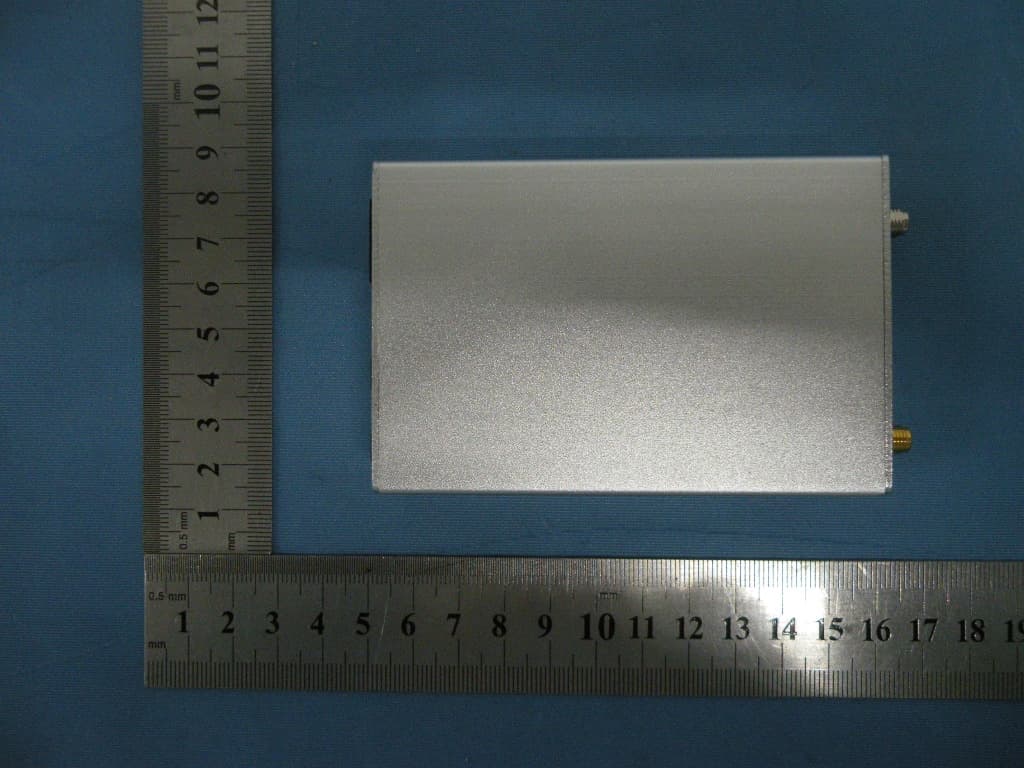
Full View To p Vi e w Bottom View Front View Rear View
ID Label/Location Info
FCC ID: X3U-TK310 Model No.: TK310 Manufacturer: Topten electronics Technology Limited
ID Label/Location Info
Label location
Internal Photos
GPRS ANTENNA GSM ANTENNA
Operational Description
Product description 1. Circuit Descriptions of GPS Vehicle Tracker(For TK310) 1. MCU chip, real-time reads the latitude and longitude output of GPS module 2. MCU chip, real-time listens and reads the commands output the SIM340DZ. 3. Through the SIM340DZ, MCU chip sends out SMS, or connect to internet to send out data by GPRS. 4. Through the ULN2003, MCU realize 5-ways control output 5. MCU through the 10-bits AD converter IO-pin to achieve two-way analog inputs 6.Trough the 5 pieces of IO-pin, MCU realize the function of detecting 5-ways signal input 7. Low power consumption can be realized by the help of the BS0302 tiny vibration sensor. 8. The Mini USB interface is used for uploading data, read/write the memory of the device 9. MCU can make 26000 pieces of latitude and longitude data to be stored in the AT45DB321 8MB RAM 10. After receipt monitoring command, MCU connects monitoring circuit to carry out monitoring. 11, The MCU Frequency is : 8MHZ 2. Main function of device Tracking via SMS or GPRS (TCP/UDP) Current location report Tracking by time interval Position logging capacity up to 260,000+ waypoints Built-in motion sensor for power saving SOS panic button Geo-fencing control Low battery alert Speeding alert Engine Cut Wiretapping (optional) Alert when TK310 enters/exits GPS blind area Alert when TK310 is turned on I/O: 5 digital inputs, 3 negative and 2 positive triggering; 5 outputs. Analog Input: 2 10 bits resolution analog inputs 3. Specifications Size of the main unit: 104mm x 62mm x 24mm Weight of the main unit: 150g Working temperature: -20° to 55° C Humidity: 5% to 95% Non-condensing Radio technology: GSM/GPRS 850/900/1800/1900 Frequency: GSM 850: 824.2MHz—848.8MHz GSM900:880.2MHz—914.8MHz GSM1800:1710.2MHz—1784.8MHz GSM1900:1850.2MHz—1909.8MHz Modulation type: GMSK RF Power: GSM850/900: 32dBm±2 GSM1800/1900: 29dBm±2 GPS chip: Latest SiRF-Star III chipset GPS Receive frequency 1575±5MHz GSM antenna and Gain External Patch Antenna, 3.5dBi Gain,SMA-B connector GPS antenna’s Gain Antenna Gain: -3dBic at 10°; 3.5dBic at zenith; Amplified Gain: 27dB typ. Working voltage: DC 12V from battery Internal Backup battery Rechargeable 3.7V 750mAh Li-ion battery
Parts List/Tune Up Info
MODEL:TK110Comment Pattern Quantity Components USB MINI Interface CN5 1 sw1 Vertical button 1 on/off Chip Capacitors 0603 11 C1,C6,C8,C9,C10,C19,C23,C35,C39,C45 ,C47 Chip Capacitors 0603 4 C34,C49,C10,C32 Chip Resistors 0603 1 R47 Chip Capacitors RB0.12 1 C2 Chip Resistors 0603 20 C52,R4,R7,R8,R13,R14,R20,R24,R25,R30,R33,R37,R38,R39,R40,R41,R42,R60,R62,R63 Chip Capacitors 0805 9 C5-1,C21,C71,C72,C73,C78,C79,C80,R34 Chip Capacitors 1005 2 C43,C100 Crystal(11.0592MH) XTAL1 1 Y2 Chip Resistors 0603 9 R15,R44,R49,R61 Diode 1206 3 D2-1,D3-1,D4-1 Chip Capacitors 0603 6 C6-1,C7,C18,C20,C22,C59 Chip Capacitors 0603 3 C50,C51,R64 Chip Resistors 0603 1 R21 2x8PIN Transposon CN8 1 CN1 Chip Resistors 0603 1 R43 Chip Resistors 0603 8 R9,R11,R18,R26,R27,R45,R46,R48 Chip Capacitors RB0.8 1 C3 Iductance L1 1 L1 SMD Transistor SOT-23 1 Q6 Crystal(8MH) SD1 1 XTL Diode 0603-1 12 D5,D11,D12,D13.D36.D14,D37,D38,D40.D41,D42,D44 Rectifier SOP-8A 1 U10 Rectifier LCC64 1 U8 Rectifier MLP-28 1 U2-1 GPS Module VPN11513 1 G1 Rectifier SOT-25 1 U6 Rectifier SO 8 1 U4 Rectifier SO-8 1 U9 LED LEDO.1 1 LED Rectifier TU5 1 U7 Rectifier SOT-25 1 U1,U2 Rectifier SOT-25 1 U3 SIM340DZ G2 1 GP2 SIM card connector CN8 1 S1 Diode 1206 1 D2,D3,D4 Diode 1210 3 C4,D454 STC12LE2052 20DGV 1 U11 ULN2003A SOP16 1 U5 SMD Transistor SOT-23 3 Q1,Q2,Q3,Q5 Vibration Sensors AIXAL0.5 1 SHK1
Parts List/Tune Up Info
TOPTEN ELECTRONICS TECHNOLOGY LIMITED Add: Room2007, Tower B, Gaoke Building, 908 Tianhe North Road, Guangzhou, China TEL: +86-20- 38351400, 38351401 FAX: +86-20-38351400 (ext.606) http://www.t10.cn . Email: [email protected] Letter of Certification This is to formally certify that: The tune up procedures of GPS vehicle Tracker (Model TK310) is not open to end user. The end user is not allowed to perform final tune. All the power and frequency set up were finished at the manufacturer stage. _____________________________________ (Commercial Director: Kenny Leung) Date: Feb.1, 2010 TOPTEN ELECTRONICS TECHNOLOGY LIMITED
RF Exposure Info
RF Exposure Statement 1. Standard Applicable According to 1.1307 (b)(1), systems operating under the provisions of this section shall be operated in a manner that ensure that the public is not exposed to radio frequency energy level in excess of the Commission’s guideline. 2. Result: This device is not portable device and for normal use, the operator will be 20cm away form the device. SAR measurement is not necessary. 3. MEP estimation at 25cm Mode CH Frequency (MHz) PK Output power (dBm) Output power (mW) antenna Gain (dBi) antenna Gain(linear) MPE 128 824.2 31.72 1485.94 3.5 2.24 0.4238 190 836.6 31.73 1489.36 3.5 2.24 0.4247 GSM 850 251 848.8 31.63 1455.46 3.5 2.24 0.4151 512 1850.2 29.03 799.83 3.5 2.24 0.2281 661 1880.0 29.07 807.24 3.5 2.24 0.2302 PCS 1900 810 1909.8 29.02 797.99 3.5 2.24 0.2276
Schematics
12345678 A B C D 8 7654321 D C B A Title NumberRevisionSize D Date:15-Dec-2009Sheet of File:E:\项目管理\汽车防盗器\GPS汽车定位器 \TK310\sch\ty310.ddb Drawn By: 1 2 3 45 6 7 8 U10 AT45DB321D 1 2 3 45 6 7 8 U9 IRF7314 1 2 3 4 5 6 7 8 9 10 11 12 13 14 15 16 1920212223242526272829303132 33 34 35 36 37 38 39 40 41 42 43 44 45 46 47 48 49505152535455565758596061626364 1718 U8 ATMEGA64L 1 2 34 5 6 U2 TS5A3157DBV2 1 2 34 5 U3 RT9013 123456789 1112151617 20 21 22 23 24 25 26 27 28 29 30 31 32 33 34 35 36 37 38 39 40 41 42 43 44 45 46 47 48 GP2 SIM340DZ R25 10K +3V GND 1 2 3 4 5 6 7 8 9 1011 12 13 14 15 16 17 18 19 20 U11 STC11L01 2051RX 2051RX R49 1K R42 10K GND R30 10K Q5 t1A R44 1K R43 300K on/off 立式按钮 GND CPU_9CPU_9 3.6V 3.6V GND 4.3V C18 1uF SHK1 VBS0302 CPU_8 CPU_8 R24 10K D44A6 D5A6 1234567 8 9 10 11 12 13 1415 16 17 18 19 20 21 U2_1 CP2102 +3V 1 2 34 5 6 U1 TS5A3157DBV2GND CPU_11 CPU_11 CPU_12 CPU_12 CPU_13 CPU_13 CPU_14 CPU_14 CPU_15 CPU_15 GND +3V CPU_18 CPU_18 R41 10K Q3 t1A R13 10K GND R14 10K R15 1K 1 2 3 45 6 7 8 U4 IRF7314 GND R20 10K C7 1uF GND +3V RESET RESET +3V GND XTAL1XTAL2 XTAL1XTAL2 C46 20pF C48 20pF GND CPU_25 CPU_25 CPU_26 CPU_26 R33 10K +3V CPU_28 R32 100 CPU_28 CPU_30 1 2 3 4 5 6 7 89 10 11 12 13 14 15 16 U5 ULN2003 CPU_30 CPU_31CPU_32 CPU_31 CPU_32 CPU_33 CPU_34 CPU_33 CPU_34 R10 100 CPU_38 CPU_38 Q1 t1A GND R7 10K R18 470K GND 12 34 56 78 910 1112 1314 1516 CN1 HEADER 8X2 CPU_39 Q2 t1A GND R8 10K R9 470K GND CN5 CN4 CN4 CN5 CPU_39 CPU_40 CPU_41 CPU_40 D14 A6 CN8 CPU_41 D13 A6 CN7 CN7CN8 CPU_42 D12 A6 CN6 CN6 CPU_42 CPU_43 CPU_43 CPU_46 CPU_46 R11 470K GND CPU_48 CPU_48 LED2 RED C49 100 CPU_37 CPU_37 +3V CPU_50 CPU_50 LED1 GREEN C34 100 +3V +3V GND D37 A6 R38 10K R37 10K GND CN14 CN14 CPU_54CPU_55 CPU_54 +3VD36 A6 R40 10K R39 10K GND CN3 CPU_55 +3V CN3 1 2 3 4 5 U7 LM2576 5V D3 SL D2 SL 4.3V3.6V C43 100uF/6V GND D4 SL R54 1K CN13DS5 LED CN13 CN13 C3 470uF/10V R51 1K CN10DS2 LED R50 1K CN9DS1 LED 5V CN9CN10 CN10 CN9 L1 100uH R52 1K CN11DS3 LED R53 1K CN12DS4 LED CN12CN11 CN12 CN11 D40 A6 R47 100K R46 470K GND U9_2 U9_2 C6 0.1uF C79 10uF 1 2 34 5 U6 TP4054 R48 470K 5V R45 470K C39 0.1uF GND U9_5 R26 470K R27 470K C10 0.1uF GND U9_5 C100 100uF/6V GND U9_5 U9_5 C19 0.1uF C22 1uF C78 10uF C80 10uF C72 10uF +3V +3V GND C20 1uF C21 10uF C23 0.1uF C59 1uF R62 10K 123456789 10 11 12 13 14 15 16 17181920212223242526 27 28 29 30 31 32 G1 GPS GPS_VCC GPS_VCC GND GPS_VCC GND 1 2 3 4 5 SW1 USB 接口 SW1_3 SW1_3 D3_1 GND SW1_2 SW1_2 D4_1 USB_VCC USB_VCC C5_1 10uF D2_1 1N4148 R4 10K C6_1 1uF GND C1 0.1uF GND GPS_TX GPS_TX +3V GND GND U4_5 U4_5 C71 10uF GND 1 2 BAT CON2 BAT_VCC BAT_VCC 2051TX 2051TX 2051TX340TX 340TX 2051TR 2051TR 64RX GND U6_1 U6_1 Y2 11.0592MHz GND CPU_6 CPU_6 +3V GND V_INPUT D45 SS24 V_INPUT GND R21 2K 1 2 GPS_TIANXIAN CON2 GND R61 1K GND GND R63 10K R60 10K R64 22 1 2 3 4 5 6 S1 SIM卡座 C45 0.1uF GND GND C32 30pF C33 30pF 1 2 MIC CON2C28 30pF C31 30pF R58 0 GND GND 1 2 GSM_TIANXIAN CON2 1 2 3 Q6 65Z5 C8 0.1uF C9 0.1uF C35 0.1uF C47 0.1uF C2 100uF/50V C52 10K R34 10uF C73 100uF/6V C50 22 C51 22 D11 A6 D38A6 D41 A6 D42 A6 C4 SS24 123 X2 8MHz
Test Report
Shenzhen Certification Technologh Service Co., Ltd 3F, Bldg27,Area A, Tanglang Industrial Zone, Xili Town, Nanshan District, ShenZhen, Guang dong, P.R. China. FCC ID: X3U-TK310 Page 1 of 39 TEST REPORT FCC ID: X3U-TK310 Applicant:Topten electronics Technology Limited Address : Room2007,Tower B,Gaoke Building, 908 Tianhe North Road, Guangzhou,China Equipment Under Test(EUT): Name : GPS Vehicle Tracker Model : TK310 In Accordance with:FCC PART 2; FCC PART 22H; FCC PART PART 24E Report No : STE100104011 Date of Test : Jan 05---06, 2010 Date of Issue : Jan 08, 2010 Test Result: PA S S In the configuration tested, the EUT complied with the standards specified above Authorized Signature ___________________________ (Mark Zhu) General Manager The manufacture should ensure that all the products in series production are in conformity with the product sample detailed in this report. If the product in this report is used in any configuration other than that detailed in the report, the manufacturer must ensure the new system complies with all relevant standards. Any mention of Shenzhen Certification Technology Service Co., Ltd. Or test done by Shenzhen Certification Technology Service Co., Ltd. Approvals in connection with, distribution or use of the product described in this report must be approved by Shenzhen Certification Technology Service Co., Ltd. Approvals in writing. Report No.:STE100104011 FCC ID: X3U-TK310 Page 2 of 39 Contents 1. General Information ...............................................................................................................4 1.1. Description of Device (EUT) ..........................................................................................4 1.2. Test Lab information .......................................................................................................4 2. Summary of test ......................................................................................................................5 2.1. Summary of test result ....................................................................................................5 2.2. Assistant equipment used for test....................................................................................5 2.3. Test mode ........................................................................................................................6 2.4. Test Environment Conditions..........................................................................................6 2.5. Measurement Uncertainty (95% confidence levels, k=2) ...............................................6 2.6. Test Equipment ...............................................................................................................7 3. Conducted Output power .......................................................................................................8 3.1. Block Diagram of Test Setup ..........................................................................................8 3.2. Limit................................................................................................................................8 3.3. Test Procedure.................................................................................................................8 3.4. Test Result.......................................................................................................................8 4. Radiated Output power ..........................................................................................................9 4.1. Block Diagram of Test Setup ..........................................................................................9 4.2. Limit................................................................................................................................9 4.3. Test Procedure.................................................................................................................9 4.4. Test Result.....................................................................................................................10 5. Occupied Bandwidth ............................................................................................................11 5.1. B lock Diagram of Test Setup ....................................................................................... 11 5.2. Limit.............................................................................................................................. 11 5.3. Test Procedure............................................................................................................... 11 5.4. Test Result.....................................................................................................................12 5.5. Orginal test data ............................................................................................................12 6. Frequency stability................................................................................................................16 6.1. Block Diagram of Test Setup ........................................................................................16 6.2. Limit..............................................................................................................................16 6.3. Test Procedure...............................................................................................................16 6.4. Test Result.....................................................................................................................17 7. Conducted spurious emissions .............................................................................................19 7.1. Block Diagram of Test Setup ........................................................................................19 7.2. Limit..............................................................................................................................19 7.3. Test Procedure.................................................…
Text truncated - open the document above for the full version.
Contact Information
Applicant
Kenny leung(Commercial Director)
Test Firm
Shenzhen Certification Technology Service Co.,LtdMark Zhu
Technical Specifications
| # | Rule Parts | Frequency Range | Power Output | Emission | Tolerance |
|---|---|---|---|---|---|
| 2 | 24E | 1.85 GHz - 1.91 GHz | 807.00 mW | 313KGXW | 34 Hz |
Other Applications from TOPTEN ELECTRONICS TECHNOLOGY LIMITED
X3U-TK210
Dec 21, 2011Wireless GPS Car Alarm
Equipment Class
PCB - PCS Licensed Transmitter
X3U-MT113
Dec 18, 2011GPS Motorcycle/Vehicle Tracker
Equipment Class
PCB - PCS Licensed Transmitter
X3U-TK110
Feb 02, 2010GPS Vehicle Tracker
Equipment Class
PCB - PCS Licensed Transmitter