X4M-2039924Sensa-LINX, Wireless Early Warning System, 2.4 GHz Variant
Smiths Detection (Watford)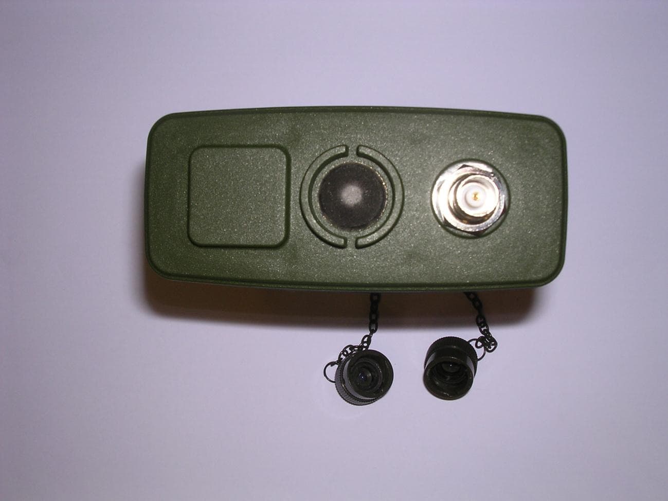
Click to zoom
Application Details
- Equipment Class
- DTS - Digital Transmission System
- Date of Grant
- Mar 27, 2012
- Application Purpose
- Original Equipment
- Date of Application
- Mar 27, 2012
- Equipment Note
- Sensa-LINX, Wireless Early Warning System, 2.4 GHz Variant
- Frequency Range
- 2410.00000000 - 2470.00000000
- Company
- Smiths Detection (Watford)
- Country
- United Kingdom
Documents & Files
Document Text
Text extracted from the exhibit documents filed with the FCC. Open a document above to read the original.
Users Manual
SENSA-LINX DETECTOR NETWORKING SYSTEM OPERATIONAL INSTRUCTIONS/USER MANUAL Prepared by: Smiths Detection Ltd. Park Avenue Bushey Watford Hertfordshire WD23 2BW U.K. Part No. 20270-1B Date of Issue: Pre Issue 2 Draft Release Feb2012 Smiths Detection Smiths Detection Smiths Detection Smiths Detection Smiths Detection Smiths Detection Smiths Detection Smiths Detection Smiths Detection Smiths Detection Smiths Detection Smiths Detection Smiths Detection Smiths Detection Smiths Detection Smiths Detection Smiths Detection Smiths Detection Smiths Detection Smiths Detection Smiths Detection Smiths Detection Smiths Detection Smiths Detection Smiths Detection Preliminary Pages Page i SENSA-LINX DETECTOR NETWORKING SYSTEM OPERATIONAL INSTRUCTIONS/USER MANUAL APPROVED BY: .......................................................................... (Technical Authority) Prepared by: Smiths Detection Ltd. Park Avenue Bushey Watford Hertfordshire WD23 2BW U.K. Part No. 20270-1B Date of Issue: Pre Issue 2 Draft Release Feb2012 Smiths Detection Smiths Detection Smiths Detection Smiths Detection Smiths Detection Smiths Detection Smiths Detection Smiths Detection Smiths Detection Smiths Detection Smiths Detection Smiths Detection Smiths Detection Smiths Detection Smiths Detection Smiths Detection Smiths Detection Smiths Detection Smiths Detection Smiths Detection Smiths Detection Smiths Detection Smiths Detection Smiths Detection Smiths Detection Preliminary Pages Page ii This page is intentionally left blank Preliminary Pages Page iii SENSA-LINX DETECTOR NETWORKING SYSTEM OPERATORS’ MANUAL TABLE OF CONTENTS FOREWORD .................................................................................................................................. vii FCC COMPLIANCE ........................................................................................................................ ix S AF E TY S UMMAR Y ........................................................................................................................ x WARNINGS & CAUTIONS ............................................................................................................... x WARNINGS ....................................................................................................................................... x CAUTIONS ..................................................................................................................................... xiii REVISION RECORD .....................................................................................................................xvii CHAPTER 1 INTRODUCTION ......................................................................................................... 1 1.1 Scope of this manual ......................................................................................................... 1 1.2 System Overview ............................................................................................................... 1 1.3 Glossary ............................................................................................................................ 2 1.4 Equipment Overview ......................................................................................................... 2 1.4.1 Command & Control (C2) System ..................................................................................... 2 1.4.2 Base Station Node/Sensor Node ....................................................................................... 4 1.4.3 Sensor Node (Radio Modem) Variants .............................................................................. 5 1.5 Ancillaries .......................................................................................................................... 6 1.5.1 Packaging.......................................................................................................................... 6 1.5.2 Consumables .................................................................................................................... 6 1.5.3 Accessories ....................................................................................................................... 6 1.6 Documentation ................................................................................................................ 13 1.7 Power Options ................................................................................................................. 13 1.7.1 C2 Laptop PC .................................................................................................................. 13 1.7.2 Sensor/Base Station Node .............................................................................................. 13 1.8 Operating Characteristics ................................................................................................ 14 1.8.1 Environmental ................................................................................................................. 14 CHAPTER 2 OPERATING INFORMATION .................................................................................... 15 2.1 Equipments Controls and Indicators ................................................................................ 15 2.1.1 Laptop PC – Controls and Features................................................................................. 15 2.1.2 Sensor Node (Radio Modem) .......................................................................................... 16 2.1.3 Sensor Node Initial Configuration .................................................................................... 16 2.1.4 Sensor Node (Radio Modem) User Interface ................................................................... 17 2.2 ‘Pull the dot’ Fasteners .................................................................................................... 18 2.3 Sensa-LINX Network Set Up & Operation........................................................................ 19 2.3…
Text truncated - open the document above for the full version.
Users Manual
Sensa-LINX DETECTOR NETWORKING SYSTEM QUICK REFERENCE GUIDE Prepared by: Smiths Detection Ltd. Park Avenue Bushey Watford Hertfordshire WD23 2BW U.K. Part No. 20449-1 Date of Issue: December 2011 Smiths Detection Smiths Detection Smiths Detection Smiths Detection Smiths Detection Smiths Detection Smiths Detection Smiths Detection Smiths Detection Smiths Detection Smiths Detection Smiths Detection Smiths Detection Smiths Detection Smiths Detection Smiths Detection Smiths Detection Page 2 © Smiths Detection Limited These commodities/technical data are controlled for export by the U.S. State Department. They may not be transferred, trans-shi pped, on a non- continuous voyage, or otherwise disposed of outside of the United States, either in their original form or after being incorporated into other end- items without the prior written approval of the U.S. Department of State. All rights reserved. No part of this publication may be reproduced or utilised in any form or by any means, electronically or m echanically, including photocopying and microfilm, without permission in writing from Smiths Detection Limited. It shall be the responsibility of the purchaser solely to establish the suitability of the product for particular applications. It is also the purchaser's responsibility to use and maintain the product in accordance with the advised procedures and recommendations. Ownership of this equipment is constrained by End User Licenc e Agreements (EULA) and the technology used in the equipment may b e subject to further military and/or commercial restrictions regarding Intellectual Property Rights (IPR) and the use or transfer of informa tion. It is the responsibility of the user to ensure that the rights of Smiths Detection are protected at all times. Smiths Detection Limited have made every effort to ensure the accuracy of this document but in accordance with our policy of co ntinuous improvement we reserve the right to make changes, without prior notice, to the equipment which is described. Smiths Detection Limited accepts no liability for any consequential loss, injury or damage resulting from the use/misuse of the supplied information or from any er rors or omissions to this manual. For further information or any other queries regarding equipment maintenance, servicing etc. contact: Customer Services Smiths Detection Limited 459 Park Avenue Bushey, Watford Hertfordshire England, WD23 2BW Tel: +44 (0) 1923 658170 Fax: +44 (0) 1923 658010 e-mail: [email protected] Page 3 1 SCOPE OF THIS MANUAL This Quick Reference Guide provides basic information about complete equipment schedules and set up details for the Sensa-LINX Detector and details to contact the equipment manufacturer. 2 IMPORTANT INFORMATION 2.1 WINDOWS DISKS The Toughbook computer you have been supplied with does not have an accompanying Windows disk from which to restore it in the event of disk failure (though it does have a recovery partition on the hard disk from which the operating system can be recovered in the even t of some disk errors or corruption). It is strongly recommended that you use the Panasonic Recovery Disc Creation Utility to create Recovery disks f or your Toughbook. You will need two blank DVDs for this purpose. NOTE that you will only be able to create one set of recovery disks. You should therefore take care not to lose these recovery disks once you have created them. 2.2 USER ACCOUNTS AND PASSWORDS Your Toughbook computer has been supplied with 2 Windows user accounts – Administrator and User. Both these accounts have been configured to have blank passwords. It is strongly recommended that you should m anage user accounts and passwords in accordance with your org anization’s operating procedures. 2.3 ANTI-VIRUS Your Toughbook computer has been supplied without any Anti-Virus software. It is recommended that you install anti-virus and se curity software in accordance with your organization’s operating procedures. Page 4 3 EQUIPMENT OVERVIEW The Sensa-LINX Detector Networking System has been designed to allo w a number of LCD 3.3 detectors (with or without Power/Comms Adaptors (PCA) or Adaptor Pouches) and LCD-NEXUS detectors to be combined as a network, wirelessly connected to a single location to pro vide centralized recording of data, and control and monitoring of the detectors. Ea ch detector is connected to a specialized radio modem. This set up is termed a Sensor Node which communicates with a radio modem connected to the Controller Laptop at the central monitoring location. This c entral monitoring location is termed the Base Station Node. The Controller Laptop has the Command & Control (C2) program installed that records, interprets and displays the data supplied by the detectors via the Sensor Node radio modems. The data acquired from the network of detectors c an then be used to produce Chemical, Biological, Radiological Nuclear and Explosives (CBRNE) reports. It is important to note that the data transmissions from the Sensor Nodes can be intercepted, however these transmissions are e ncrypted using the Sensa-LINX system and cannot read by other agencies. The radio modems have built-in Global Positioni ng System (GPS) receivers to obtain posit ion co-ordinates from GPS satellites an d display their position on a GIS map. Functioning GPS is not vital to the operati on of the Sensa-LINX system. The GPS receiver is activated at startup but may be disabled to conserve battery power if the Sensor Node is used on a Fixed Installation. If the Sensor Node is used in a mobile s ituation the GPS signal will update the Sensor Node’s position when movement is detected. Depending on the type of radio modem used the network may be either a mesh network or a non-mesh network. In a mesh network the radio modems within transmission range of the Base Station Node ‘repeat’ the signals from the radio m odems of Sensor Nodes beyond the nominal transmission range or where there are ‘line-of-sight’ probl…
Text truncated - open the document above for the full version.
Block Diagram
Electrical Engineering Radio 868MHz GPS 1575.42 MHz OR EXT PWR Radio 2.4GHz Radio 900MHz OR SBC 454MHz RTC 32.768kHz EXT PWR SW FREQ (U7 – LTC3824) 490kHz 5V REG (U8 – LTC3112) 750kHz 1 Smiths Detection C2 BASE STATION COMPUTER (APPROVED) EXTERNAL PWR SUPPLY (APPROVED)
Operational Description
SYSTEM OVERVIEW The Sensa-LINX Detector Networking System is equipment to allow a collection of sensors to be combined into a network, wirelessly connected to a base station to provide centralized control and monitoring of the data. Each sensor is connected to a Sensor Node (Radio Modem) which communicates with another Sensor Node (Radio Modem) at the Base Station Node connected to the Laptop PC (Base Station). This system is intended for remote monitoring of an unmanned perimeter of sensors, monitoring a network of worn sensors as personnel move through an area, collation of data from multiple sensors into a single tactical map, and combinations of the above tasks. The Laptop PC uses data acquired from the network of sensors to produce standard CBRNE report messages. The Sensor Nodes (Radio Modems) have built-in Global Positioning System (GPS) receivers that obtain position co-ordinates. The GPS receiver is then disabled soon after start up to conserve battery power. The GPS capability is re-enabled when the Sensor Node’s (Radio Modem’s) accelerometer detects movement. Due to operating restrictions in different countries, a number of Sensor Node (Radio Modem) variants are offered. These include an International and Standard 2.4GHz variant, an International and Standard 900MHz variant, and an International and Standard 868MHz variant. Each of these has its own characteristics which can be seen in TABLE 2 Radio Modem Variants. The Sensa-LINX system can currently interface to the Smiths Detection LCD3.3, LCD Nexus and CAM XTR chemical sensors.
Parts List/Tune Up Info
Qua ntityDesignatorDescriptionCommentManufacturer1Footprint 1 SBC1 KARO TX28 SINGLE BOARD COMPUTER, 26mm SO-DIMM KARO TX28/400/64S/128 F/I KARO ELECTRONICS PN:TX28/400/64S/128F/I SBC KARO TX25 SMT SOCKETED 1 A1 ASSEMBLY, RF MODULE, 2.4GHzXBP24-AUI-250 MAXSTREAM PN: XBP24- AUI-001 XBP24-AUI-XXX SMT SOCKETED 1 BH1BATTERY, HOLDER, 1225500KEYSTONE PN: 500 BATTERY HOLDER 12- 16mm 1 B1BATTERY, 1225, 3VBR1225PANASONIC PN: BR1225 BATTERY 12.5mm, SOCKETED 1 C58 CAPACITOR, CERAMIC, 5%, 50V, 680pF08055A681JAT2A0805 1 C59 CAPACITOR, CERAMIC, 5%, 50V, 47pF08055A470JAT2A0805 1 C6 CAPACITOR, CERAMIC, 10%, 100V, 220pF08051C221KAT2A0805 1 C74 CAPACITOR, CERAMIC, 10%, 100V, 22nF08051C223KAT2A0805 2 C23, C25 CAPACITOR, CERAMIC, 10%, 10V, 1uF C0805C105K8RA C0805 2 C64, C66 CAPACITOR, CERAMIC, 10%, 250V, 0.1uF C1206C104KARA CTU1206 2 C9, C34 CAPACITOR, CERAMIC, 10%, 100V, 2.2uF C1210C225K1RA C1210 25 C1, C2, C3, C4, C5, C7, C16, C17, C18, C21, C26, C28, C29, C30, C35, C36, C43, C44, C48, C49, C51, C70, C71, C73, C76 CAPACITOR, CERAMIC, 10%, 100V, 0.1uF C0805C104K1RA C0805 3 C10, C50, C57 CAPACITOR, CERAMIC, 5%, 50V, 100pF08055A101JAT2A0805 4 C61, C62, C63, C65 CAPACITOR, CERAMIC, 10%, 250V, 22nF C0805C223KARA CTU0805 4 C67, C68, C69, C78 CAPACITOR, CERAMIC, 10%, 100V, 0.01uF08051C103KAT2A0805 5 C12, C19, C22, C24, C79 CAPACITOR, CERAMIC, 10%, 25V, 1uF08053C105KAT2A0805 5 C13, C38, C39, C40, C41 CAPACITOR, CERAMIC, 5%, 100V, 22pF08051A220JAT2A0805 5 C15, C52, C53, C54, C55 CAPACITOR, CERAMIC, 10%, 100V, 1nF C0805C102K1RA C0805 1 C11 CAPACITOR, TANTALUM, 10%, 20V, 100uF T495E107K020AT E0607260-38 1 C27 CAPACITOR, TANTALUM, 10%, 10V, 47uF B45196H2476K30 96032-28 1 C42 CAPACITOR, TANTALUM, LOW ESR, 10%, 20V, 33uF B45197A4336K40 97343-31 1 C60 CAPACITOR, SUPER, 5.0V, 0.47uFPM-5R0V474-R COOPER/BUSSMANN PN: PM-5R0V474-R PM-5R0V474-R SUPER CAP 2 C14, C32 CAPACITOR, TANTALUM, 10%, 20V, 47uF T495X476K020AT E0657343-43 2 C20, C37 CAPACITOR, TANTALUM, 20%, 10V, 10uF T491A106M010A T3216-18 2 C31, C75 CAPACITOR, TANTALUM, 10%, 25V, 1uF T495A105K025ZT E4K03216-18 2 C8, C33 CAPACITOR, TANTALUM, 20%, 50V, 10uF T495X106M050A TE3007343-43 3 C47, C72, C77 CAPACITOR, TANTALUM, LOW ESR, 10%, 25V, 4.7uF T494A475M025A T3216-18 1 J1 CONNECTOR, SINGLE ROW, 0.5mm, 18POSXF2M-1815-1AOMRON XF2M-1815-1A CON_SMT OMRON XF2M- 18 1 J4 CONNECTOR, SODIMM SOCKET, DDR1 & DDR21473005-1TYCO PN: 1473005-1 CON_SMT TYCO 1717468- 3 2 J2, J3 CONNECTOR, DUAL ROW, 50mil, 16POSM50-4900845 HARWIN PN: M50- 4900845 CON_SMT HARWIN 1.27mm 2x8, EXTENDED 2 J5, J6 CONNECTOR, SOCKET, SINGLE ROW, 10POSSMM-110-02-S-S SAMTEC PN: SMM-110-02- S-S CON_SMT SOCKET 1- ROW 2MM 10POS 1 D15DIODE, RECTIFIER, 3A, 600VS3J-E3/57TVISHAY PN: S3J-E3/57TSMC 1 D17 DIODE, SWITCHING, 75V, 175mABAS16W-7-F DIODES INC PN: BAS16W- 7-FSOT323 A1,C3 1 D16DIODE, ZENER, 13V, 350mWBZX84C13-7-F DIODES INC PN: BZX84C13-7-FSOT23 A1,C3 1 D18DIODE, ZENER, 39V, 350mWBZX84C39-7-F DIODES INC PN: BZX84C39-7-FSOT23 A1,C3 5 D6, D7, D13, D20, D21DIODE, SCHOTTKY, 60VB360A-13-F DIODES INC PN: B360A- 13-FSMA 1 D10 DIODE, TVS, BI- DIRECTIONAL, 8.5VSMBJ8.5CABOURNS PN: SMBJ8.5CASMB, NON-POLARAIZED 1 D14 DIODE, TVS, BI- DIRECTIONAL, 100VSMBJ100CABOURNS PN: SMBJ100CASMB, NON-POLARAIZED 5 FB1, FB3, FB4, FB5, FB6FERRITE BEAD, 3A, 25 mOHM742792114WURTH PN: 742792114 FERRITE BEAD- WURTH1206 1 F1FUSE, THERMAL, 1.5A1206L150THWR LITTELFUSE PN: 1206L150THWR1206 1 U14 IC, QUAD, BUFFER, NON- INVERTING, 3-STATEMC74HC126ADG ON SEMI PN: MC74HC126ADGSO14 1 U13 IC, CONVERTER, USB TO SERIAL RS232FT232RLFTDI PN: FT232RLTSSOP28 1 U2 MODULE, ETHERNET MAGNETICS, 1 PORTH1102NLPULSE PN: H1102NLH1102NL 1 U3 IC, ACCELEROMETER, MOTION SENSOR, 3-AXISLIS331DLHST PN: LIS331DLHLGA16 1 U10 IC, REGULATOR, LOW NOISE, LDO, 100mA LT1761IS5- 3#TRPBF LINEAR PN: LT1761IS5- 3#TRPBFTSOT23-5 1 U15 IC, SINGLE UV/OV VOLTAGE MONITOR LTC2912ITS8- 2#TRMPBF Linear: LTC2912ITS8- 2#TRMPBFTSOT23-8 1 U8 IC, CONVERTER, DC-DC, REGULATED OUTPUT, 2.5A LTC3112EFE#PB F LINEAR PN: LTC3112EFE#PBFTSSOP20 EXPOSED PAD 1 U7 IC, CONTROLLER, STEP- DOWN, HIGH VOLTAGE LTC3824IMSE#P BF LINEAR PN: LTC3824IMSE#PBF MSOP10 EXPOSED DIE PAD 1 U6 IC, POWER PATH CONTROLLERLTC4412IS6#PBF LINEAR PN: LTC4412IS6#PBFTSOT23 1 U4IC, EEPROM, I2C BUS, 64KM24C64-WDW6PST PN:M24C64-WDW6PTSSOP8 1 U17 IC, MOSFET PWR SW, P- CHANNEL, 1.2AMAX893LESA+MAXIM PN: MAX893LESA+SO8 1 U1IC, TRANSCEIVER, RS-232MAX3222EEUP MAXIM PN: MAX3222EEUPTSSOP20 1 U16 IC, VOLTAGE DETECTOR, 3.0V NCP303LSN30T1 G ON SEMI PN: NCP303LSN30T1GSOT25(23-5) 1 U18 IC, BUS EXPANDER, I2C, 8- BITPCA9500PWNXP PN: PCA9500TSSOP16 1 U19IC, CURRENT MONITORZXCT1009 DIODES INC PN: ZXCT1OxxZXCT10xx (SOT23) 1 L1INDUCTOR, SHIELDED, 47uH MSS1278T- 473ML COILCRAFT PN: MSS1278T-473ML INDUCTOR_SMT COILCRAFT MSS1278T 1 L10 INDUCTOR, SHIELDED, 850mA, 47uH29473CMURATA PN: 29473CINDUCTOR_SMT 2900 1 L9 INDUCTOR, SHIELDED, 1.3A, 100uHB82477G2104M EPCOS PN: B82477G2104M INDUCTOR_SMT EPCOS B82477G2 2 L2, L3INDUCTOR, SHIELDED, 4.7uHMSS1048-472NL COILCRAFT PN: MSS1048- 472NL INDUCTOR_SMT COILCRAFT MSS1048 4 JP1, JP2, JP3, JP4 JUMPER, 2-CKT, 2MM, JUMPER, 4-CKT, 2MM57202-G52-02LFFCI PN: 57202-G52-02LFCON_SMT FCI 57202-2 1 D1DIODE, LED, AMBER HSMA-A100- Q00J1 AVAGO PN: HSMA-A100- Q00J1 LED_SMT AVAGO HSMx PLCC-2 3 D2, D3, D4DIODE, LED, GREEN HSMM-A101- R00J1 AVAGO HSMM-A101- R00J1 LED_SMT AVAGO HSMx PLCC-2 8 Q4, Q5, Q6, Q7, Q9, Q14, Q15, Q16 MOSFET, N-CHANNEL, 1.9A, 30VFDN357NFAIRCHILD PN: FDN357NSOT23 G1,S2,D3 1 Q17 MOSFET, N-CHANNEL, 20V, 4ANTJS3157NT1G ON SEMI PN: NTJS3157NT1GSOT363 4 Q2, Q3, Q10, Q18 MOSFET, P-CHANNEL, 1A, 20VNDS332PFAIRCHILD PN: NDS332PSOT23 G1,S2,D3 1 Q1MOSFET, P-CHANNEL, -30VNDT456PFAIRCHILD PN: NDT456PSOT223 G1,S3,D2&4 1 Q13 MOSFET, P-CHANNEL, 150V, 13A IRF6215STRLPB FIR PN: IRF6215STRLPBFD2PAK G1,S3,D2&4 1 Q8MOSFET, P-CHANNEL, 60VIRFL9014VISHAY PN: IRFL9014SOT223 G1,S3,D2&4 1 U9IC, REGULATOR, 1.5A, 3.3V LT1963AEFE- 3.3#PBF LINEAR TECH PN: LT1963AEFE-3.3#PBFTSSOP16 EXPOSED PAD 1 U11IC, REGULATOR, 3.0VXC6219B302MR TOREX PN: XC6219B302MRSOT25(23-5…
Text truncated - open the document above for the full version.
Schematics
A B C D A B C D DWG NO.SHREV. 7654213 EE 7654321 REVISION HISTORY ZONEREV.DESCRIPTIONDATEAPPROVED CONTRACT NO: 23667 .XXX`.005 .XX`.010 TOLERANCES ARE: DECIMAL: ANGLE: .X`.10 `1° 2202 LAKESIDE BLVD. EDGEWOOD, MD 21040 DATE ADDITIONAL APPROVALS THIS INFORMATION CONTAINED IN THIS DOCUMENT, OR ANY REPRODUCTION THEREOF, IS PROPRIETARY INFORMATION AND THE PROPERTY OF SMITHS DETECTION. IT SHALL NOT BE DISCLOSED, COPIED, DUPLICATED, OR USED FOR MANUFACTURE, PRODUCTION OR PROCUREMENT, W ITHOUT THE EXPRESS PERMISSION OF SMITHS DETECTION. PRECIOUS METAL INDICATION CODE WEIGHTS STRESS MATERIALS & PROCESSES QUALITY ASSURANCE DATEAPPROVAL PART DASH NO. FINALNEXT QTY REQ'D PER ASSY USED ONNEXT ASSY ACT WT .CALC WT. APPLICATION SIMLAR TO FINISH TREATMENT INTERPRET DIMENSIONS AND TOLERANCES PER ASME Y14.5M-1994 INTERPRET DRAWING IAW ASME Y14.100M-2000 DIMENSIONAL LIMITS APPLY AFTER FINISH DO NOT SCALE DRAWING THIRD ANGLE PROJECTION UNLESS OTHERWISE SPECIFIED ALL SURFACES CAST MACH INTERPRET SURFACE TEXTURE DESIGNATIONS IAW ANSI Y14.36M-1996 UNLESS OTHERWISE SPECIFIED DIMENSIONS ARE IN INCHES PROJ. ENGR. CAGE MFG APPR PROGRAM APPROVAL ENGINEER CHECKED DRAWN OFSHEET SCALE REV DWG NOSIZE TITLE Cannot open file N:\Engineering\Altium Libraries\Templates\Smiths_DET_lin e_pos_blue.jpg "These commodities/technical data are controlled for export by the U.S. State Department. They may not be transferred, transshipped on a noncontinuous voyage, or otherwise be disposed of outside of the United States, either in thier orginial form or after being incorporated into other end-items, without the prior written approval of the U.S. Department of State." Project Bridge 22 B 20353 J. SCHANZLE 15 JUN 2011 PP2 Prototype BRIDGE CPU CCA DGND BATT_MON EXTERNAL DC POWER INPUT BATTERY POWER INPUT BATTERY MONITOR DGND +VBATT BATT_MON +EXT_SUPPLY +3.5V TO +7.2V TP1 EXT FILTERED POWER TP2 +8.8V TP4 +3.5V TO +8.7V TP3 1 32 4 Q1 NDT456P 1 3 24 Q8 IRFL9014 VIN 1 GND 2 CTL 3 STAT 4 GATE 5 SENSE 6 U6 LTC4412IS6#PBF 10K R13 3.32K R14 0.0 R112 D6 B360A-13-F D7 B360A-13-F 47uH L1 4.7uH L250V 10uF C33 50V 10uF C8 20V 100uF C11 100V 0.1uF C7 100V 0.1uF C18 25V 1uF C12 100V 2.2uF C9 100V 1nF C15 50V 100pF C10 100V 220pF C6 0.033 R1 1M R3 1K R5 150K R6 15K R7 15K R2 150K R4 GND1 1 SYNC/MODE 2 Rset 3 Vc 4 Vfb 5 SS 6 SEN SE 7 Vcc 8 GATE 9 CAP 10 GND11 11 U7 LTC3824IMSE#PBF 1 2 3 4 5 SW1 ELUM-EE-SA-Q-6-C22 POWER POWER FAIL INTERRUPT CONTROLLER LOW_PWR_INT# LOW_PWR_INT# +VSUPPLY GPS_1PPS V_BU 1 2 3 4 5 6 7 8 9 10 11 12 13 14 15 16 17 18 J1 XF2M-1815-1A TP8 2K R47 2K R46 DGND DGND DGND DGND DGND DGND GPS_PWR_CTRL GPS_TXD GPS_RXD BATTERY AND GPS CCA CONNECTION GPS_PWR_CTRL DGND +5V 10V 1uF C25 VIN 1 Vss 2 CE 3 NC 4 VOUT 5 U11 XC6219B302MR 33.2K R45 GPS_PWR 10V 1uF C23 DGND DGND D10 SMBJ8.5CA 20V 33uF C42 25V 1uF C24 49.9 R71 25V 1uF C19 DC TO DC REGULATOR TP5 TP7 25V 1uF C22 42.2K R9 845K R11 +5V 100V 0.1uF C16 100V 0.1uF C17 4.7uH L3 50V 680pF C58 150K R12 33.2K R10 50V 47pF C59 D13 B360A-13-F 12 FB1 742792114 100V 1nF C52 100V 1nF C53 100V 1nF C54 100V 1nF C55 100V 0.1uF C51 50V 100pF C50 50V 100pF C57 10K R70 20V 47uF C14 DGND +5V RESET CONTROLLER 100V 22pF C13 Vfalling-trip = 3.6V 20353B2 SEE SHEET 1 D14 SMBJ100CA +EXT_SUPPLY 250 V 22 nF C61 D15 S3J-E3/57T+VEXT_FILT +VEXT_FILT EXTERNAL SUPPLY FILTERING IN 2 GND 3 RST OUT 1 CD 5 NC 4 U16 NCP303LSN30T1G 100V 0.01uF C69 100uH L9 250 V 22 nF C62 250 V 22 nF C63 47 OHM 0.75W R74 47 OHM 0.75W R75 250 V 0.1uF C64 47 OHM 0.75W R76 250 V 22 nF C65 250 V 0.1uF C66 100V 0.01uF C67 2.2K R80 2K R81 27K R78 100 R77 100 R84 1K R83 100 R82 2.2K R86 100V 22nF C74 4.7K R85 0.1 OHM R79 RESET_OUT# RESET_OUT# Vfalling-trip = 3.0V Please note this email / fax / document contains export controlled technical data. These commodities/technical data are authorized by the U.S. Government for export only to the United Kingdom for use by Smiths Detection Watford Ltd. They may not be transferred, transshipped on a non-continuous voyage, or otherwise be disposed of in any other country, either in their original form or after being incorporated into other end-items, without the prior written approval of the U.S. Department of State. These commodities are authorized for export to Smiths Detection Watford Ltd. under Department of State approval MA2036-09. The information contained within these documents /information is proprietary data as written by Smiths Detection and is not intended for further dissemination to other companies or third parties without authorisation from Smiths Detection Watford UK. These are the legal requirements under the Export Control Order 2008. These documents and information are controlled under licence UKGL/05/02729/1P. 3 2 1 Q11 BC856BW-7-F 1 2 3 Q12 FMMTA42 1 3 2 D16 BZX84C13-7-F 1 3 2 D18 BZX84C39-7-F 1 32 4 Q13 IRF6215STRLPBF 12 FB3 742792114 12 FB4 742792114 12 FB5 742792114 12 FB6 742792114 D20 B360A-13-F 1 OHM R8 47uH L10 1.5A F1 33.2K R88 +9V TO +32V TP9 2 3 1 D17 BAS16W-7-F 100V 0.1uF C76 U8_RUN 100V 0.01uF C68 DGND +VBATT_FUSED U8_VOUT GND1 1 COMP 2 FB 3 OVP 4 VIN 5 VIN 6 RUN 7 IOUT 8 VOUT 9 GND10 10 GND11 11 SW2 12 SW2 13 BST2 14 SW1 15 SW1 16 BST1 17 VCC 18 PWM 19 GND20 20 GND21 21 U8 LTC3112EFE#PBF 100V 2.2uF C34 DGND DGND +3.5V TO +8.7V 5.36K R69 15 JUN 2011 J. SIEBERT DIS 1 UV 2 OV 3 GND 4 TMR 5 VL 6 VH 7 VCC 8 U15 LTC2912ITS8-2#TRMPBF 33.2K R68 33.2K R49 +3.3V VH 10K R65 NOTES: DO NOT INSTALL (DNI) DNI 5V 0.47F C60 IOUT 1 VS+ 2 VS- 3 U19 ZXCT1009 IOUT_MON +VSUPPLY +VSUPPLY +VSUPPLY IOUT_MON 0.1 OHM R29 2K R31 DGND 100V 0.1uF C43 CURRENT SWITCHMONITOR 100V 0.01uF C78 VIN 1 GND 2 SHDN 3 BYP 4 VOUT 5 U10 LT1761IS5-3#TRPBF DGNDDGND 25V 1uF C79 GPS VBACKUP 25V 4.7uF C77 DNI DNI HOLD UP CAPACITOR 33.2 R73 52.3K R72 DGND CAP_DISCHRG CAP_DISCHRG CAPACITOR DISCHARGE CONTROL 1.2K R87 4.3K R89 100K R92 DGND 1 3 2 4 56 Q17 NTJS3157NT1G PIC601PIC602 COC6 PIC701 PIC702 COC7 PIC801 PIC802 COC8 PIC901 PIC902 COC9 PIC1001 PIC1002 COC10 PIC1101 PIC1102 COC11 PIC1201 PIC1202 COC12 PIC1301 PIC1302 COC13 PI…
Text truncated - open the document above for the full version.
Test Report
MET Laboratories, Inc. Safety Certification - EMI - Telecom Environmental Simulation 914 WEST PATAPSCO AVENUE ! BALTIMORE, MARYLAND 21230-3432 ! PHONE (410) 354-3300 ! FAX (410) 354-3313 33439 WESTERN AVENUE ● UNION CITY, CALIFORNIA 94587 ● PHONE (510) 489-6300 ● FAX (510) 489-6372 3162 BELICK STREET ● SANTA CLARA, CALIFORNIA 95054 ● PHONE (408 748-3585 ● FAX (510) 489-6372 The Nation’s First Licensed Nationally Recognized Testing Laboratory Dosimetric Assessment Test Report for Smith Detection Tested and Evaluated In Accordance With FCC OET 65 Supplement C: 01-01 Prepared for Smith Detection, Inc. -CASC 2202 Lakeside Blvd. Edgewood, MD 21040 Engineering Statement: The measurements shown in this report were made in accordance with the procedures specified in Supplement C to OET Bulletin 65 of the Federal Communications Commission (FCC) Guidelines [FCC 2001] and Industry Canada RSS-102 for uncontrolled exposure. I assume full responsibility for the accuracy and completeness of these measurements, and for the qualifications of all persons taking them. It is further stated that upon the basis of the measurements made, the equipment evaluated is capable of compliance for localized specific absorption rate (SAR) for uncontrolled environment/general population exposure limits specified in ANSI/IEEE Std. C95.1-1999. Smith Detection Sensa-Linx SAR Report MET Report: EMCS32460-SAR © 2012, MET Laboratories, Inc. Page i of iii SAR Evaluation Certificate of Compliance APPLICANT: Smith Detection Applicant Name and Address: Smith Detection, Inc. -CASC 2202 Lakeside Blvd. Edgewood, MD 21040 Test Location: MET Laboratories, Inc. 3162 Belick Street Santa Clara, CA 95054 USA EUT: Sensa-Linx Date of Receipt: November 1, 2011 RF exposure environment: Uncontrolled Exposure/General Population RF exposure category: Portable Power supply: 6VDC (4 AA Batteries) Antenna: 900MHz – 4dBi / 2400MHz – 4dBi Production/prototype: Production Modulation: 900MHz – FSK / 2400MHz – O-QPSK Duty Cycle: 100% TX Range: 904 - 926 MHz 2410 - 2470 MHz Max SAR Measured SAR 1g (m/W/kg) Body: 0.069 0.037 Anderson Soungpanya Wireless Project Engineer Smith Detection Sensa-Linx SAR Report MET Report: EMCS32460-SAR © 2012, MET Laboratories, Inc. Page ii of iii Report Status Sheet Revision Report Date Reason for Revision 0 November 1, 2011 Initial Release. Smith Detection Sensa-Linx SAR Report MET Report: EMCS32460-SAR © 2012, MET Laboratories, Inc. Page iii of iii Table of Contents INTRODUCTION ................................................................................................................................................ 1 SAR DEFINITION ............................................................................................................................................... 1 DESCRIPTION OF DEVICE UNDER TEST (EUT) .......................................................................................... 2 SAR MEASUREMENT SYSTEM ....................................................................................................................... 3 MEASUREMENT SUMMARY ........................................................................................................................... 4 DATA EVALUATION PROCEDURES ............................................................................................................. 10 SYSTEM PERFORMANCE CHECK ................................................................................................................ 12 SIMULATED EQUIVALENT TISSUES ........................................................................................................... 14 SAR SAFETY LIMITS ...................................................................................................................................... 15 ROBOT SYSTEM SPECIFICATIONS .............................................................................................................. 16 1.1. Specifications ................................................................................................................. 16 1.2. Data Acquisition Electronic (DAE) System: .........................................…
Text truncated - open the document above for the full version.
Contact Information
Applicant
Richard Wilkinson(Mr)
Technical Contact
Smith�s DetectionAlastair Beadle
[email protected]+44 (0) 1923 658299
459 Park Avenue · Watford, Herts · United Kingdom
Non-Technical Contact
Smith�s DetectionTravis Bruns
[email protected]301-831-4708
Test Firm
EUROFINS ELECTRICAL AND ELECTRONIC TESTING NA, INCGreg Kovolenko
Technical Specifications
| # | Rule Parts | Frequency Range | Power Output |
|---|---|---|---|
| 1 | 15C | 2.41 GHz - 2.47 GHz | 216.00 mW |
Other Applications from Smiths Detection (Watford)
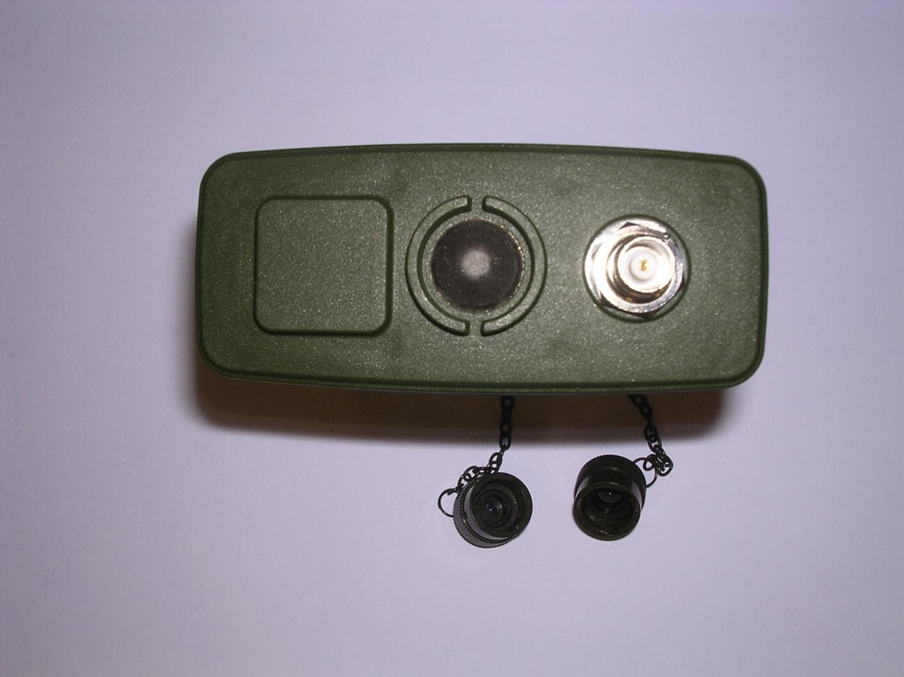
X4M-20399900
Mar 18, 2012Sensa-LINX, Wireless Early Warning System, 900 MHz Variant
Equipment Class
DTS - Digital Transmission System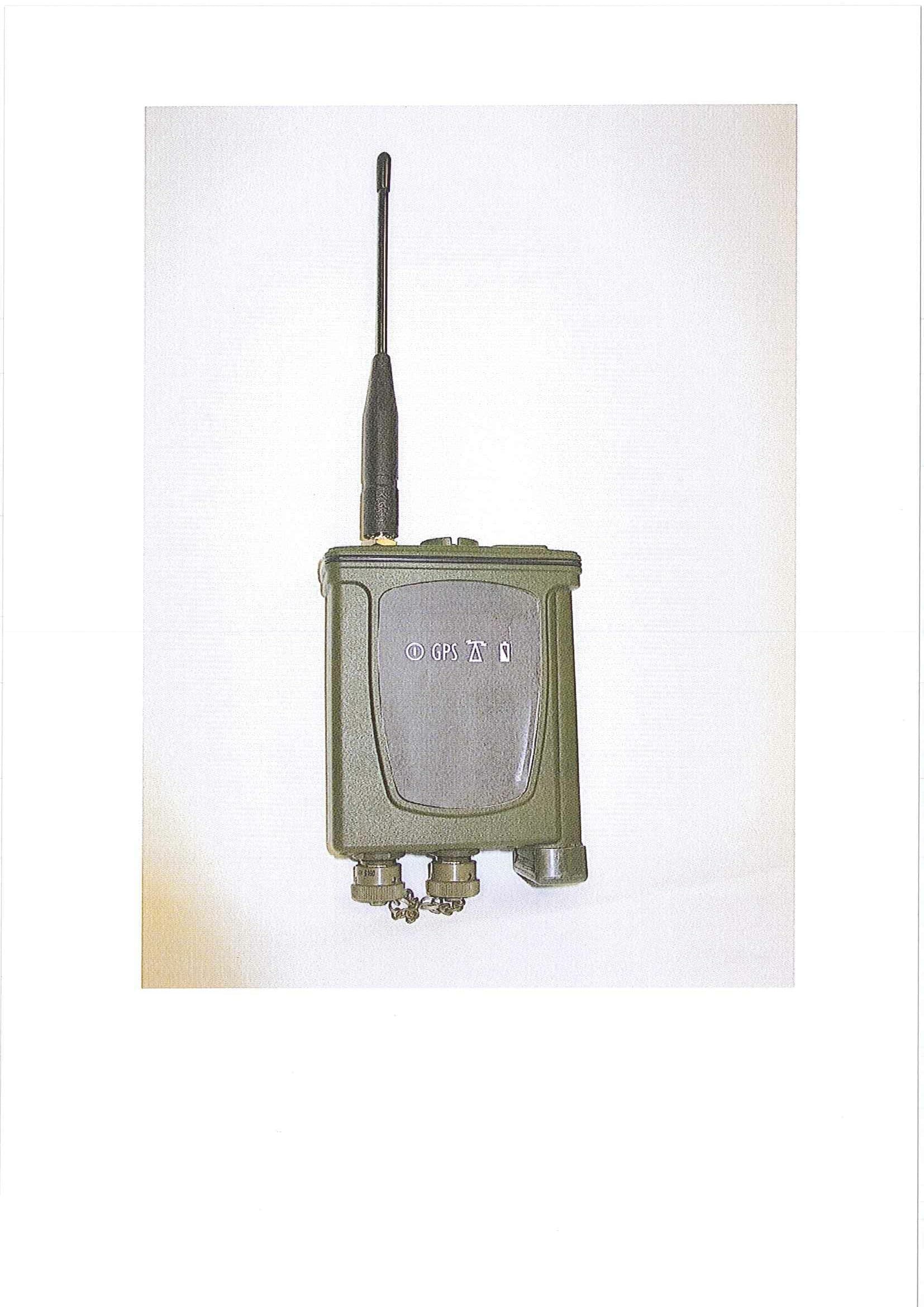
X4M-16852
May 13, 2010Part 15 Low Power Tranceiver, Rx Verified
Equipment Class
DSS - Part 15 Spread Spectrum Transmitter