X4M-20399900Sensa-LINX, Wireless Early Warning System, 900 MHz Variant
Smiths Detection (Watford)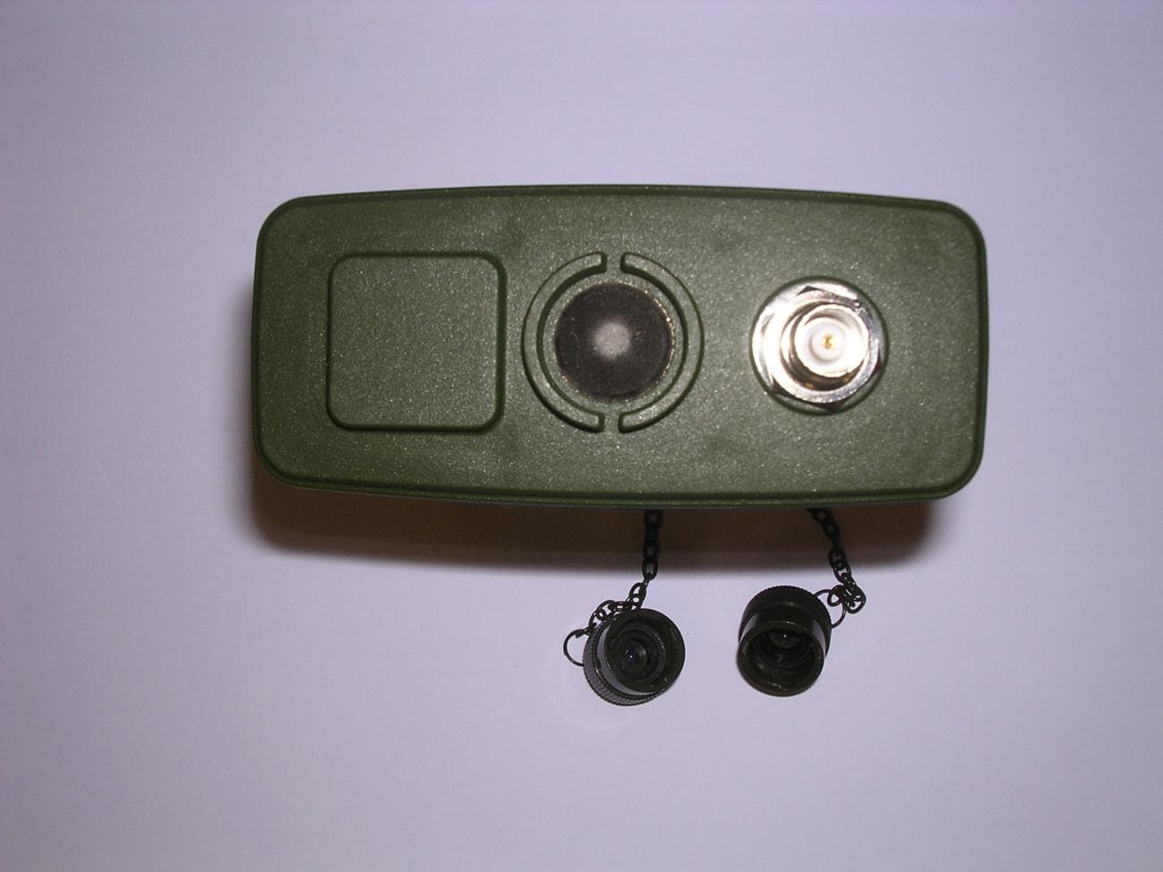
Click to zoom
Application Details
- Equipment Class
- DTS - Digital Transmission System
- Date of Grant
- Mar 18, 2012
- Application Purpose
- Original Equipment
- Date of Application
- Mar 18, 2012
- Equipment Note
- Sensa-LINX, Wireless Early Warning System, 900 MHz Variant
- Frequency Range
- 904.00000000 - 926.00000000
- Company
- Smiths Detection (Watford)
- Country
- United Kingdom
Documents & Files
Document Text
Text extracted from the exhibit documents filed with the FCC. Open a document above to read the original.
Test Report
MET Laboratories, Inc. Safety Certification - EMI - Telecom Environmental Simulation 914 WEST PATAPSCO AVENUE ! BALTIMORE, MARYLAND 21230-3432 ! PHONE (410) 354-3300 ! FAX (410) 354-3313 33439 WESTERN AVENUE ● UNION CITY, CALIFORNIA 94587 ● PHONE (510) 489-6300 ● FAX (510) 489-6372 3162 BELICK STREET ● SANTA CLARA, CALIFORNIA 95054 ● PHONE (408 748-3585 ● FAX (510) 489-6372 The Nation’s First Licensed Nationally Recognized Testing Laboratory Dosimetric Assessment Test Report for Smith Detection Tested and Evaluated In Accordance With FCC OET 65 Supplement C: 01-01 Prepared for Smith Detection, Inc. -CASC 2202 Lakeside Blvd. Edgewood, MD 21040 Engineering Statement: The measurements shown in this report were made in accordance with the procedures specified in Supplement C to OET Bulletin 65 of the Federal Communications Commission (FCC) Guidelines [FCC 2001] and Industry Canada RSS-102 for uncontrolled exposure. I assume full responsibility for the accuracy and completeness of these measurements, and for the qualifications of all persons taking them. It is further stated that upon the basis of the measurements made, the equipment evaluated is capable of compliance for localized specific absorption rate (SAR) for uncontrolled environment/general population exposure limits specified in ANSI/IEEE Std. C95.1-1999. Smith Detection Sensa-Linx SAR Report MET Report: EMCS32460-SAR © 2012, MET Laboratories, Inc. Page i of iii SAR Evaluation Certificate of Compliance APPLICANT: Smith Detection Applicant Name and Address: Smith Detection, Inc. -CASC 2202 Lakeside Blvd. Edgewood, MD 21040 Test Location: MET Laboratories, Inc. 3162 Belick Street Santa Clara, CA 95054 USA EUT: Sensa-Linx Date of Receipt: November 1, 2011 RF exposure environment: Uncontrolled Exposure/General Population RF exposure category: Portable Power supply: 6VDC (4 AA Batteries) Antenna: 900MHz – 4dBi / 2400MHz – 4dBi Production/prototype: Production Modulation: 900MHz – FSK / 2400MHz – O-QPSK Duty Cycle: 100% TX Range: 904 - 926 MHz 2410 - 2470 MHz Max SAR Measured SAR 1g (m/W/kg) Body: 0.069 0.037 Anderson Soungpanya Wireless Project Engineer Smith Detection Sensa-Linx SAR Report MET Report: EMCS32460-SAR © 2012, MET Laboratories, Inc. Page ii of iii Report Status Sheet Revision Report Date Reason for Revision 0 November 1, 2011 Initial Release. Smith Detection Sensa-Linx SAR Report MET Report: EMCS32460-SAR © 2012, MET Laboratories, Inc. Page iii of iii Table of Contents INTRODUCTION ................................................................................................................................................ 1 SAR DEFINITION ............................................................................................................................................... 1 DESCRIPTION OF DEVICE UNDER TEST (EUT) .......................................................................................... 2 SAR MEASUREMENT SYSTEM ....................................................................................................................... 3 MEASUREMENT SUMMARY ........................................................................................................................... 4 DATA EVALUATION PROCEDURES ............................................................................................................. 10 SYSTEM PERFORMANCE CHECK ................................................................................................................ 12 SIMULATED EQUIVALENT TISSUES ........................................................................................................... 14 SAR SAFETY LIMITS ...................................................................................................................................... 15 ROBOT SYSTEM SPECIFICATIONS .............................................................................................................. 16 1.1. Specifications ................................................................................................................. 16 1.2. Data Acquisition Electronic (DAE) System: ................................................................. 16 1.3. Phantom(s): .................................................................................................................... 16 SAR Measurement System ................................................................................................................................. 17 1.4. RX90BL Robot .............................................................................................................. 17 1.5. Robot Controller ............................................................................................................. 17 1.6. Light Beam Switch ......................................................................................................... 17 1.7. Data Acquisition Electronics .......................................................................................... 17 1.8. Electo-Optical Converter (EOC) .................................................................................... 18 1.9. Measurement Server ....................................................................................................... 18 1.10. Dosimetric Probe ........................................................................................................ 18 1.11. SAM Phantom ............................................................................................................ 18 1.12. Planar Phantom ........................................................................................................... 18 1.13. Validation Planar Phantom ......................................................................................... 18 1.14. Device Holder ............................................................................................................. 19 1.15. System Validation Kits .....................................................…
Text truncated - open the document above for the full version.
Test Report
XBee-PRO 900 Model No.: XBEE09P FCC ID: MCQ-XBEE09P Applicant: Digi International Inc. 11001 Bren Road East Minnetonka, MN 55343 USA In Accordance With Federal Communications Commission (FCC) Part 15, Subpart C, Section 15.247 Digital Modulation Systems (DTS) Operating in 902–928 MHz Band UltraTech's File No.: MXS-068F15C247 This Test report is Issued under the Authority of Tri M. Luu, Professional Engineer, Vice President of Engineering UltraTech Group of Labs Date: February 7, 2008 Report Prepared by: Dan Huynh Issued Date: February 7, 2008 Tested by: Mr. Hung Trinh, EMI/RFI Technician Test Dates: August 23 - 29, 2007 September 19-21, 2007 October 19, 2007 The results in this Test Report apply only to the sample(s) tested, and the sample tested is randomly selected. This report must not be used by the client to claim product endorsement by NVLAP or any agency of the US Government. UltraTech 3000 Bristol Circle, Oakville, Ontario, Canada, L6H 6G4 Tel.: (905) 829-1570 Fax.: (905) 829-8050 Website: www.ultratech-labs.com , Email: [email protected], Email: [email protected] 0685 31040/SIT C-1376 46390-2049 200093-0 SL2-IN-E-1119R FCC Part 15, Subpart C, Section 15.247 – DTS Contents i XBee-PRO 900, Model XBEE09P FCC ID: MCQ-XBEE09P ULTRATECH GROUP OF LABS File #: MXS-068F15C247 3000 Bristol Circle, Oakville, Ontario, Canada L6H 6G4 February 7, 2008 Tel. #: 905-829-1570, Fax. #: 905-829-8050, Email: [email protected] , Website: http://www.ultratech-labs.com All test results contained in this engineering test report are traceable to National Institute of Standards and Technology (NIST) TABLE OF CONTENTS EXHIBIT 1. SUBMITTAL CHECK LIST ..........................................................................................................................................1 EXHIBIT 2. INTRODUCTION ............................................................................................................................................................2 2.1. SCOPE ............................................................................................................................................................................................2 2.2. RELATED SUBMITTAL(S)/GRANT(S).......................................................................................................................................2 2.3. NORMATIVE REFERENCES .......................................................................................................................................................2 EXHIBIT 3. PERFORMANCE ASSESSMENT .................................................................................................................................3 3.1. CLIENT INFORMATION ..............................................................................................................................................................3 3.2. EQUIPMENT UNDER TEST (EUT) INFORMATION.................................................................................................................3 3.3. EUT’S TECHNICAL SPECIFICATIONS......................................................................................................................................4 3.4. ASSOCIATED ANTENNA DESCRIPTION .................................................................................................................................4 3.5. LIST OF EUT’S PORTS.................................................................................................................................................................4 3.6. ANCILLARY EQUIPMENT ..........................................................................................................................................................5 EXHIBIT 4. EUT OPERATING CONDITIONS AND CONFIGURATIONS DURING TESTS...................................................6 4.1. CLIMATE TEST CONDITIONS ...................................................................................................................................................6 4.2. OPERATIONAL TEST CONDITIONS & ARRANGEMENT FOR TESTS.................................................................................6 EXHIBIT 5. SUMMARY OF TEST RESULTS..................................................................................................................................7 5.1. LOCATION OF TESTS..................................................................................................................................................................7 5.2. APPLICABILITY & SUMMARY OF EMC EMISSION TEST RESULTS ..................................................................................7 5.3. MODIFICATIONS INCORPORATED IN THE EUT FOR COMPLIANCE PURPOSES............................................................7 EXHIBIT 6. MEASUREMENTS, EXAMINATIONS & TEST DATA FOR EMC EMISSIONS ..................................................8 6.1. TEST PROCEDURES ....................................................................................................................................................................8 6.2. MEASUREMENT UNCERTAINTIES ..........................................................................................................................................8 6.3. MEASUREMENT EQUIPMENT USED .......................................................................................................................................8 6.4. ESSENTIAL/PRIMARY FUNCTIONS AS DECLARED BY THE MANUACTURER...............................................................8 6.5. POWER LINE CONDUCTED EMISSIONS [§15.207(a)]............................................................................... ..............................9 6.6. OCCUPIED BANDWIDTH [§ 15.247(a)(2)] ............................................................................................................................... 13 6.7. PEAK CONDUCTED OUTPUT POWER - DTS [§ 15.247(b)(3)] ..................…
Text truncated - open the document above for the full version.
Contact Information
Applicant
Richard Wilkinson(Mr)
Technical Contact
Smiths DetectionAlastair Beadle
[email protected]+44 (0) 1923 658299
459 Park Ave. · Watford, Herts · United Kingdom
Non-Technical Contact
Smiths DetectionTravis Bruns
[email protected]301-831-4708
Test Firm
MET Laboratories, Inc.Jon Fuhrman
Technical Specifications
| # | Rule Parts | Frequency Range | Power Output |
|---|---|---|---|
| 1 | 15C | 904 MHz - 926 MHz | 131.00 mW |
Other Applications from Smiths Detection (Watford)
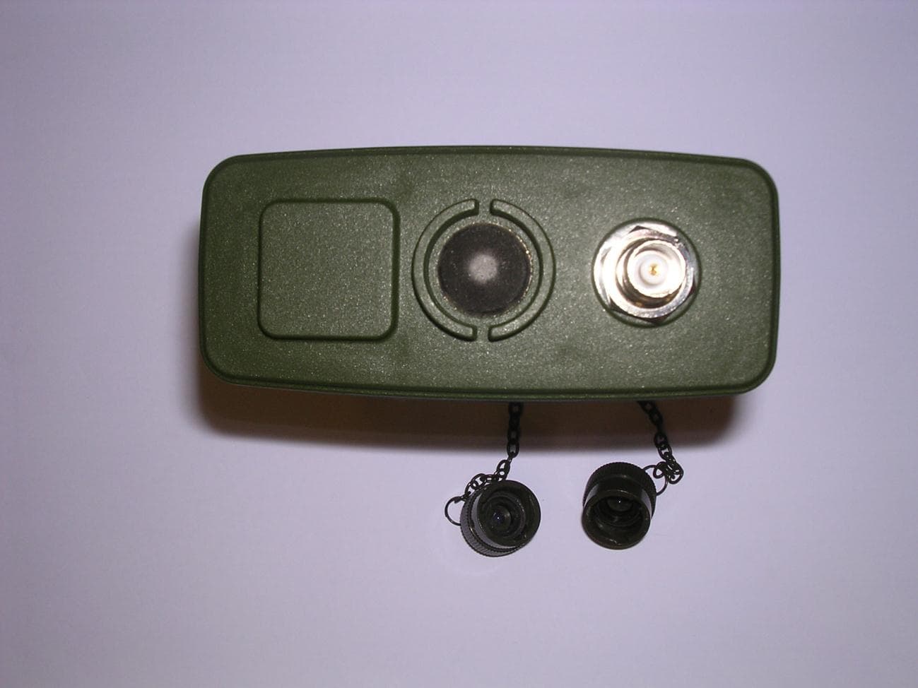
X4M-2039924
Mar 27, 2012Sensa-LINX, Wireless Early Warning System, 2.4 GHz Variant
Equipment Class
DTS - Digital Transmission System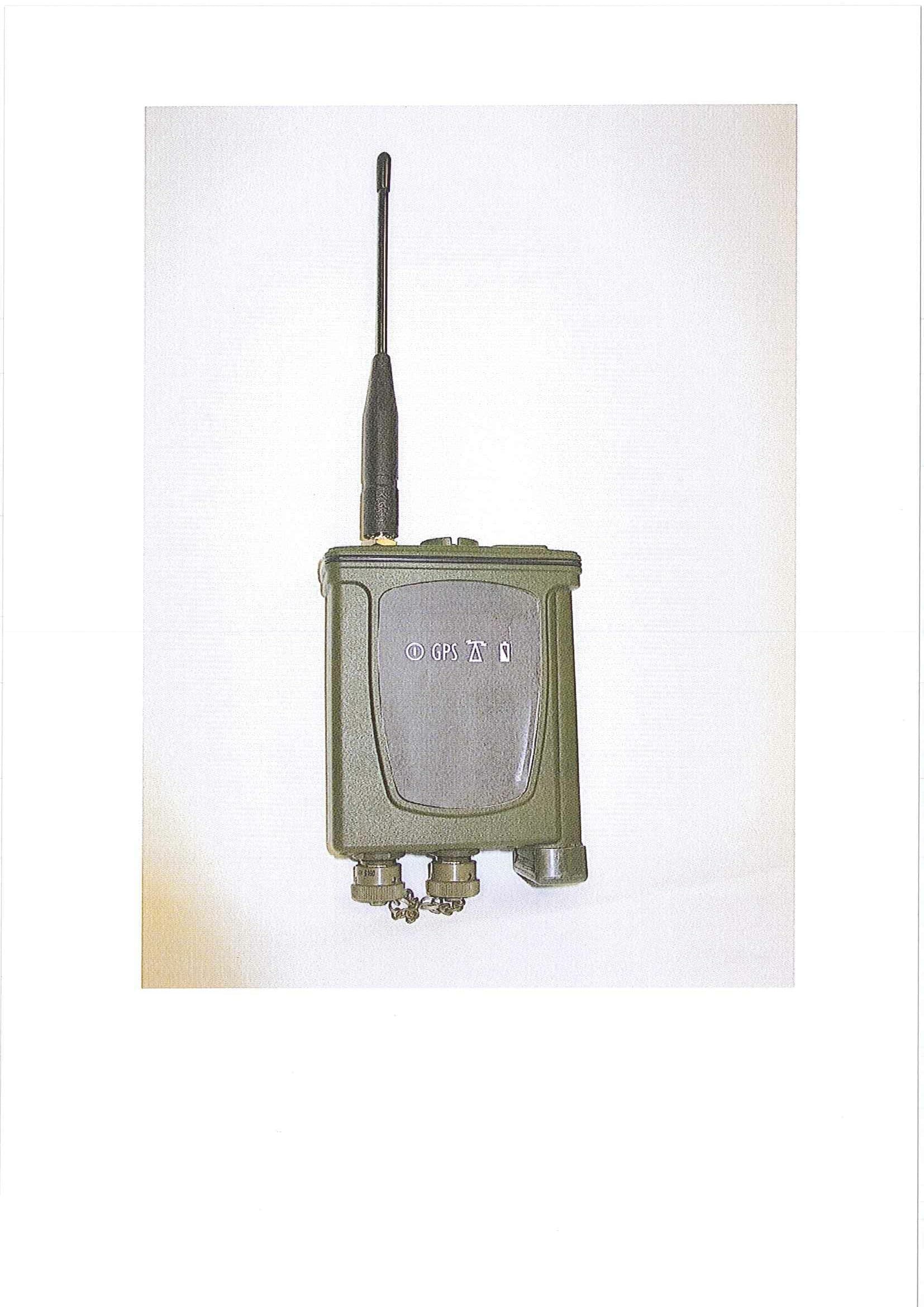
X4M-16852
May 13, 2010Part 15 Low Power Tranceiver, Rx Verified
Equipment Class
DSS - Part 15 Spread Spectrum Transmitter