X66C1-2011PEBBLE
Hitevision Digital Media Technology Co., Ltd.
Click to zoom
Application Details
- Equipment Class
- DXX - Part 15 Low Power Communication Device Transmitter
- Date of Grant
- Jan 13, 2011
- Application Purpose
- Original Equipment
- Date of Application
- Jan 13, 2011
- Equipment Note
- PEBBLE
- Frequency Range
- 2405.00000000 - 2480.00000000
- Country
- China
Documents & Files
Document Text
Text extracted from the exhibit documents filed with the FCC. Open a document above to read the original.
Users Manual
Using the Pebble pad learning response system with ClassComm software Quick set up guide Leaders in learning technology Minimum system requirements: • Processor: Pentium III 450 MHz processor (1 gigahertz (GHz) Pentium processor recommended) • Memory: 256 MB (512 MB or above recommended) • Display: 800 x 600, 256 colours (Recommended: 1024 x 768 high colour, 32-bit) • CDROM Drive: 4x or faster • HDD: 300MB free hard drive space for basic installation – 500 MB hard drive space required for curriculum sample content • Microsoft.Net Framework 2.0 (included in installer) • Microsoft® PowerPoint 2003 or above • Adobe Flash player version 9 (included in installer) • Operating System: Windows XP, Windows Vista and Windows 7 Compatible Quick set up guide for Pebble pad learning response systems using ClassComm software Software CD with Quick Set Up Guide What’s in the case Pebble pad Learning Response System Participant handsets These are used by participants to send responses Presenter handset Used by the presenter to control the presentation ReceiverUSB cable Step 1 Step 2 Pebble pads use AA batteries (see image 2). Prepare the handsets 1. Pebble pad battery cover being removed 3. Battery cover being screwed on2. Batteries being inserted ClassComm software installation Please ensure that the receiver is disconnected before you insert the ClassComm Installation CD. • If the CD does not auto-run, you will need to manually run “ClassComm.exe” by exploring the CD contents (Fig 1) Fig. 1 – ClassComm CD Contents The ClassComm Installation Menu Screen will open as shown below. • Select ClassComm Installation from the options. • Follow the onscreen wizard instructions to install the software. • The main ClassComm software installation is now complete. Note – do not launch the software at this stage. Please follow through this guide to completion. ClassComm Installation Menu Screen Prepare the handsets Step 3 • There is some optional sample content that can be installed for use with the ClassComm system. This step will add complete, mapped educational content for use with the ClassComm system. • From ClassComm Installation Menu Screen, select the Sample Content button. • Follow the on-screen wizard instructions to install the required sample content. • When the main ClassComm software is launched, the sample content will be installed into the Resources area. Sample content installation (optional) Step 4 Install the Powerpoint plug-in (slide mapper) Note – You will need Microsoft® Powerpoint® 2003 or above installed on your PC before you install the plug-in 1. The PowerPoint Plug-in or Slide Mapper is a utility that is added directly into your Microsoft® PowerPoint® application. It allows for the mapping of your presentations within PowerPoint. The mapping process assigns question data to your slides (Example: True/ False, Multiple Choice, Numeric and so on) 2. From ClassComm Installation Menu Screen, select the Power Point Plug-in button. 3. Follow the on-screen instructions to install the Power Point Plug-in (Slide Mapper) module. 4. The Slide Mapper will appear as shown below within Microsoft PowerPoint® Slide Mapper within PowerPoint Step 5 Connect the receiver and test handset communication within ClassComm Connect the ClassComm receiver to an available USB port on the PC. A red LED will light up in the receiver. • At this stage, the PC will automatically detect the receiver and configure the drivers accordingly. NOTE – The receiver drivers are installed during the ClassComm software installation described in STEP 3 – CLASSCOMM SOFTWARE INSTALLATION of this guide. It is important to install ClassComm software before attaching the receiver. • Launch the ClassComm software by clicking the icon from the desktop or from Start > All Programs > ClassComm. • A message in the bottom-left area of the ClassComm Software will appear stating that the receiver has connected successfully. Step 6 • Click on the Communication tab within ClassComm. This will display the communication grid as shown. If pressing any keys on the Pebble Pad handsets show a red LED, then that handset is not MAPPED to the receiver and will not communicate. Press any keys on the handsets and a cell will light up in the Communication grid. The software is now installed and the hardware is configured correctly and has been tested in the communication area of ClassComm. Connect the receiver and test handset communication within ClassComm Press and hold the -/? key within 5-10cm of the connected receiver. The communication LED will blink GREEN 3 times when mapping is complete. A non-mapped handset will show a red light when any key is pressed. • Open a blank PowerPoint Presentation and add a question with 4 choices as shown in the example below • Select the following options from the Slide Mapper to match the information on the slide • Slide Type: Multiple Choice • Response Type: Text • Answer : Select the correct answer choice • Answer Colour: Green • Question: Cut and paste the question text from the slide here • Text Answers: From the slide, highlight the correct answer and click the Add button. Say “Yes” to the confirmation message that appears. That’s it! The basic slide functionality has been set as multiple choice with 4 text label choices (A-D) and the correct answer to be highlighted in green when the presenter reveals the answer during a presentation. Repeat the above steps as necessary and save the presentation. For more information on the different question types and Slide Mapper, consult the ClassComm User Guide (See section on Adding and mapping a PowerPoint Presentation) Creating a presentation Step 7 Add the presentation into ClassComm resources • From within the ClassComm RESOURCES area, go to File > New > New Activity > New PowerPoint Activity. • From the New Activity window, click the Browse button to navigate to the presentation created in STEP 7 and click OK. • The presentation will now appear in the RESOURCES tree struct…
Text truncated - open the document above for the full version.
Block Diagram
Block Diagram of Receiver CC2510(MIANM CU+RF) FT245BL(USB TO parallel communication) 5V TO 3.3V LDO USBPORT (5V_POWER) COPPER ANTENNA 26MHz CRYSTAL 6MHz CRYSTAL
Cover Letter(s)
Hitevision Digital Media Technology Co., Ltd. January 12, 2010 Federal Communications Commission Authorization and Evaluation Division 1435 Oakland Mills Road Columbia, MD 21046 SUBJECT: FCC Application for FCC ID: X66C1-2011 To Whom It May Concern: We, the undersigned, hereby attest to the fact that we will apply the Declaration of Conformity procedure to the class B computer peripheral portion (USB Port) of this composite filing. Regards, Hitevision Digital Media Technology Co., Ltd. ------------------------------- Ligen Wang (Superintend)
Cover Letter(s)
HiteVision Digital Media Technology Co., Ltd. Letter of Authorization FCC ID: X66C1-2011 Dec. 25, 2010 Federal Communications Commission Authorization and Evaluation Divisoin 7435 Oakland Mills Road Columbia, MD 21046 To Whom It’s My Concern: We, the undersigned,hereby Authorize Anbotek Compliance Laboratory Limited (Daniel Zhu) on our behalf, to apply to the Federal Communications Commission on our equipment. Any and all acts carried out by Anbotek Compliance Laboratory Limited (Daniel Zhu). On our behalf shall have the same effect as acts of our own. This Authorization expires on Jan. 30, 2011 This is to advise that we are in full compliance with the Anti-Drug Abuse Act. We, HiteVision Digital Media Technology Co., Ltd., are not subject to a denial of federal benefits pursuant to section 5301 of the Anti-Drug Abuse Act of 1988.21 USC835a, and no party to the application is subject to a denial of federal benefits pursuant to that section. Sincerely, Ligen Wang Superintend
External Photos
Page 20 of 22 FCC ID: X66C1-2011 Anbotek Compliance Laboratory Limited Report No.201012768F-1 Figure 1 The EUT-Front View Figure 2 The EUT-Back View
ID Label/Location Info
FCC ID Label Sample for FCC ID: X66C1-2011 FCC ID: X66C1-2011 This device complies with Part 15 of the FCC Rules. Operation is subject to the following two conditions: 1. This device may not cause harmful interference, and 2. This device must accept any interference received, including interference that may cause undesired operation.
ID Label/Location Info
The proposed Label Location on EUT Proposed FCC ID Label Location Proposed Label Location on EUT The EUT-Bottom View/Proposed FCC ID Label Location
Internal Photos
Page 21 of 22 FCC ID: X66C1-2011 Anbotek Compliance Laboratory Limited Report No.201012768F-1 Figure 3 PCB of the EUT-Front View Figure 4 PCB of the EUT-Back View Page 22 of 22 FCC ID: X66C1-2011 Anbotek Compliance Laboratory Limited Report No.201012768F-1 Figure 5 PCB of the EUT-Front View (RF Module)
Operational Description
Circuit Function Description for Receiver 1. MCU with RF: responsible for communication with handset. 2. USB chip: responsible for communication between MCU & computer. 3. Powered by 5V USB port. 4. When received a button code value which sent by handset, MCU will send this code value to PC through the USB chip. 5. MCU & RF crystal frequency is 26MHz. 6. USB chip crystal frequency is 6MHz. 7. The device uses an copper 2.4GHz antenna. 8. The antenna gain is 3.5dBi.
Schematics
1 2 3 4 56 ABCD 6 5 4 3 2 1 D CBA Title Number Revision Size B Date: 10-Dec-2010 Sheet of File: C:\Users\hp\Deskt op\ 简易版表决器电路图纸 \cc2510rc.ddb Drawn By: D1 1N5819 C5104 C7104 DC5V 3V3 C1103 L110uH LED1red R20100 EC2 47uF/10V EC3100uF/10V ZD1 5.6V F1SMD0805P075TF Usb power 2 1 3 VV GND IN OUT U1FST3301A33GM 1234 USB1CON4 Usb power D0 1 D4 2 D2 3 VCCIO 4 D1 5 D7 6 GND 7 NC 8 D5 9 D6 10 D3 11 PWREN# 12 RD# 13 WR 14 USBDP 15 USBDM 16 3V3OUT 17 GND 18 RESET# 19 VCC 20 GND 21 TXE# 22 NC 24 RXF# 23 AGND 25 TEST 26 OSCI 27 OSCO 28 U3FT245RL C9100nF Y512M C11 27PF C12 27PF DC5V C21100N RBIAS 27 AVDD 26 AVDD 25 RF_N 24 RF_P 23 AVDD 22 XOSC_Q1 21 XOSC_Q2 20 AVDD 19 P1_3 36 P1_4 35 P1_5 34 P1_6 33 P1_7 32 RESET_N 31 DCOUPL 30 AVDD_DREG 29 GUARD 28 P0_4 9 P0_3 8 P0_2 7 P0_1 6 P0_0 5 P1_0 4 P1_1 3 DVDD 2 P1_2 1 P2_4 18 P2_3 17 P2_2 16 P2_1 15 P2_0 14 P0_7 13 P0_6 12 P0_5 11 DVDD 10 U2 CC2510 C291100N C191220P C221100N C251100N C261220P R27156K Q1Q2RF_NRF_P Y1 26M CQ1CAP CQ2CAP Q1 Q2 C301100N 3V3 L230INDUCTOR C221u P1_2P1_1P1_0P0_0P0_1P0_2P0_3P0_4 P0_7 P0_5 P0_6 P2_0 P2_1 P2_2 P2_3 P2_4 P1_3 P1_4 P1_6 P1_5 P1_7 3V3 3V3 3V3 RESET 1 ANTANT L2321N2 C234CAP C233CAP C232CAP C242 CAP C231 CAP C241 CAP L231INDUCTOR L241INDUCTOR RF_NRF_P DC5V P0_0P0_4P0_2P0_1P0_7P0_5P0_6P0_3P1_1P1_2 R25RES1 P1_5 P1_4P1_3 reset R443k 3V3 RESET VCC C101CAP
Test Report
Page 1 of 22 FCC ID: X66C1-2011 Anbotek Compliance Laboratory Limited Report No.201012768F-1 FCC TEST REPORT for HiteVision Digital Media Technology Co., Ltd. Pebble Model No.: C1-2011, VT300-R Report Number : 201012768F-1 Date of Test : Dec. 23~31, 2010 Date of Report : Jan. 08, 2011 Prepared for : HiteVision Digital Media Technology Co., Ltd. Address : No. 1 Building, Hong Hui Industrial Park, Liu Xian No. 2 Road, No. 68 Zone, Bao An District, Shen Zhen, China Prepared By : Anbotek Compliance Laboratory Limited Address : 1/F, 1 /Building, SEC Industrial Park, No.4 Qianhai Road, Nanshan District, Shenzhen, 518054, China Tel: (86) 755-26014771 Fax: (86) 755-26014772 Page 2 of 22 FCC ID: X66C1-2011 Anbotek Compliance Laboratory Limited Report No.201012768F-1 TABLE OF CONTENT Description Page Test Report 1. GENERAL INFORMATION .........................................................................................................4 1.1. Description of Device (EUT)....................................................................................................................4 1.2. Description of Test Facility ......................................................................................................................5 1.3. Measurement Uncertainty.........................................................................................................................5 2. MEASURING DEVICE AND TEST EQUIPMENT.................................................................... 6 3. TEST PROCEDURE ....................................................................................................................... 7 4. CONDUCTED LIMITS .................................................................................................................. 8 4.1. Block Diagram of Test Setup ...................................................................................................................8 4.2. Power Line Conducted Emission Measurement Limits (15.207) .............................................................8 4.3. Configuration of EUT on Measurement ...................................................................................................8 4.4. Operating Condition of EUT ....................................................................................................................8 4.5. Test Procedure ..........................................................................................................................................9 4.6. Power Line Conducted Emission Measurement Results ..........................................................................9 5. RADIATION INTERFERENCE.................................................................................................. 12 5.1. Requirements (15.249, 15.209): .............................................................................................................12 5.2 Test Procedure .........................................................................................................................................12 5.3 Test Results..............................................................................................................................................12 6. OCCUPIED BANDWIDTH..........................................................................................................16 6.1. Requirements (15.249): ..........................................................................................................................16 6.2 Test Results..............................................................................................................................................16 7. PHOTOGRAPH............................................................................................................................. 18 7.1. Photo of Power Line Conducted Emission Measurement ......................................................................18 7.2. Photo of Radiation Emission Test ..........................................................................................................18 APPENDIX I (Photos of EUT) (3 Pages) Page 3 of 22 FCC ID: X66C1-2011 Anbotek Compliance Laboratory Limited Report No.201012768F-1 TEST REPORT Applicant : HiteVision Digital Media Technology Co., Ltd. Manufacturer : Genee World EUT : Pebble Model No. : C1-2011, VT300-R Serial No. : N/A Rating : DC 5V Trade Mark : Measurement Procedure Used: FCC Part15 Subpart C, Paragraph 15.249, 15.209 & 15.207 The device described above is tested by Anbotek Compliance Laboratory Limited to determine the maximum emission levels emanating from the device and the severe levels of the device can endure and its performance criterion. The measurement results are contained in this test report and Anbotek Compliance Laboratory Limited is assumed full of responsibility for the accuracy and completeness of these measurements. Also, this report shows that the EUT (Equipment Under Test) is technically compliant with the FCC Part 15 Subpart C requirements. This report applies to above tested sample only and shall not be reproduced in part without written approval of Anbotek Compliance Laboratory Limited Date of Test : Dec. 23~31, 2010 Prepared by : (Engineer / Rock Zeng) Reviewer : (Project Manager / Coco Xiang) Approved & Authorized Signer : (Manager / Tom Chen) Page 4 of 22 FCC ID: X66C1-2011 Anbotek Compliance Laboratory Limited Report No.201012768F-1 1. GENERAL INFORMATION 1.1. Description of Device (EUT) EUT : Pebble Model Number : C1-2011, VT300-R (Note: The above samples are same except the model number & Size of appliances, so we prepare “C1-2011” for EMC test only.) Test Power Supply : AC 120V, 60Hz for PC System PC : Manufacturer: DELL M/N: OPTIPLEX 380 S/N: 1J63X2X CE , FCC: DOC MONITOR : Manufacturer: DELL M/N: E170Sc S/N: CN-00V539-64180-055-0UPS CE , FCC: DOC MOUSE : Manufacturer: DELL M/N: M-UARDEL7 S/N: N/A CE , FCC: DOC KEYBOARD : Manufacturer: DELL M/N: SK-8115 S/N: CN-0DJ313-7…
Text truncated - open the document above for the full version.
Test Setup Photos
Page 18 of 22 FCC ID: X66C1-2011 Anbotek Compliance Laboratory Limited Report No.201012768F-1 7. PHOTOGRAPH 7.1. Photo of Power Line Conducted Emission Measurement 7.2. Photo of Radiation Emission Test
Contact Information
Applicant
Ligen Wang(Quality Engineer)
Test Firm
Shenzhen Anbotek Compliance Laboratory LimitedDaniel zhu
[email protected]86-755-26014771
Technical Specifications
| # | Rule Parts | Frequency Range | Power Output |
|---|---|---|---|
| 1 | 15C | 2.40 GHz - 2.48 GHz | - |
Other Applications from Hitevision Digital Media Technology Co., Ltd.

X66WMI-02
Jun 12, 2012WIRELESS MODULE FOR IR COM-IR WHITEBOARD INTERFACE BOX
Equipment Class
DXX - Part 15 Low Power Communication Device Transmitter
X66WMD-02
Jun 12, 2012WIRELESS MODULE FOR IR COM-DONGLE
Equipment Class
JBP - Part 15 Class B Computing Device Peripheral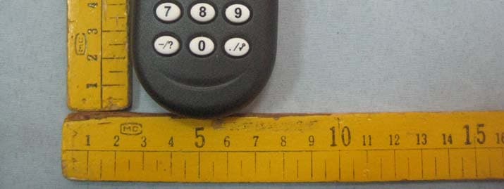
X66C1
Jan 13, 2011PEBBLE
Equipment Class
DXX - Part 15 Low Power Communication Device Transmitter
X66-WMI-01A
Mar 22, 2010WHITEBOARD WIRELESS MODULE-IR BOX
Equipment Class
DXX - Part 15 Low Power Communication Device Transmitter
X66-WMD-01
Feb 25, 2010WHITEBOARD WIRELESS MODULE-DONGLE
Equipment Class
DXX - Part 15 Low Power Communication Device Transmitter