X6O-AAC00XXarea monitor
Dräger Safety AG & Co. KGaA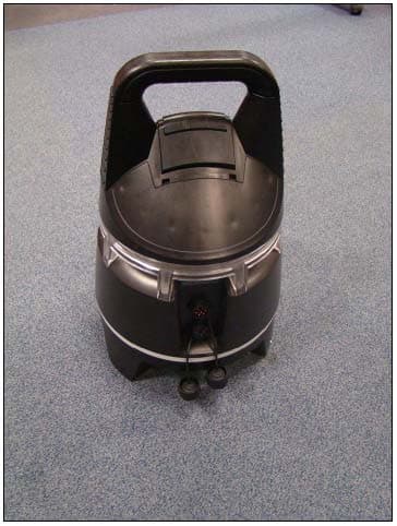
Click to zoom
Application Details
- Equipment Class
- DTS - Digital Transmission System
- Date of Grant
- Mar 29, 2010
- Application Purpose
- Original Equipment
- Date of Application
- Mar 29, 2010
- Equipment Note
- area monitor
- Frequency Range
- 917.00000000 - 926.00000000
- Company
- Dräger Safety AG & Co. KGaA
- Country
- Germany
Documents & Files
Document Text
Text extracted from the exhibit documents filed with the FCC. Open a document above to read the original.
Users Manual
de Gebrauchsanweisung 2 en Instructions for Use fr Notice d’utilisation es Instrucciones de uso it Istruzioni per l'uso nl Gebruiksaanwijzing da Brugsanvisning no Bruksanvisning Dräger X-zone 5000 03333112.eps DRAFT 02 - 08/02/10 2 For Your Safety . . . . . . . . . . . . . . . . . . . . . . . . . . . . . 3 Intended Use . . . . . . . . . . . . . . . . . . . . . . . . . . . . . . . 3 Description . . . . . . . . . . . . . . . . . . . . . . . . . . . . . . . . 3 What is what . . . . . . . . . . . . . . . . . . . . . . . . . . . . . . . 4 Operation . . . . . . . . . . . . . . . . . . . . . . . . . . . . . . . . . . 5 Switching on the instrument . . . . . . . . . . . . . . . . . . 5 Dräger X-am 5x00 info mode . . . . . . . . . . . . . . . . . 6 Switching off the device . . . . . . . . . . . . . . . . . . . . 6 Power supply for the Dräger X-am 5x00 with NiMH battery in the Dräger X-zone 5000: . . . 6 Perform a function test with gas . . . . . . . . . . . . . . 7 Perform a connection test . . . . . . . . . . . . . . . . . . . 7 Safety housing . . . . . . . . . . . . . . . . . . . . . . . . . . . . 7 Alarm-attenuation ring . . . . . . . . . . . . . . . . . . . . . . 7 Establishing a wireless connection . . . . . . . . . . . . 8 Connecting devices via a cable connection . . . . . 10 Relay output: . . . . . . . . . . . . . . . . . . . . . . . . . . . . 11 During operation . . . . . . . . . . . . . . . . . . . . . . . . . 12 Alarms (default settings) . . . . . . . . . . . . . . . . . . . . 12 Concentration pre-alarm A1 . . . . . . . . . . . . . . . . . 13 Concentration main alarm A2 . . . . . . . . . . . . . . . 13 Battery pre-alarm . . . . . . . . . . . . . . . . . . . . . . . . . 13 Battery main alarm . . . . . . . . . . . . . . . . . . . . . . . . 13 Device alarm . . . . . . . . . . . . . . . . . . . . . . . . . . . . 13 Operation with pump (optional) . . . . . . . . . . . . . . 14 Commissioning and performing the measurement . . . . . . . . . . . . . . . . . . . . . . . . . . . . 14 Observe the following during measuring mode with pump . . . . . . . . . . . . . . . . . . . . . . . . . 15 Device configuration . . . . . . . . . . . . . . . . . . . . . . . 15 Faults, Cause, Remedy . . . . . . . . . . . . . . . . . . . . . 16 Fault messages . . . . . . . . . . . . . . . . . . . . . . . . . 18 Maintenance . . . . . . . . . . . . . . . . . . . . . . . . . . . . . . 19 Maintenance intervals . . . . . . . . . . . . . . . . . . . . . 19 Replacing the batteries . . . . . . . . . . . . . . . . . . . . 19 Charging the batteries . . . . . . . . . . . . . . . . . . . . . 20 Care . . . . . . . . . . . . . . . . . . . . . . . . . . . . . . . . . . . . . 20 Disposing of the device . . . . . . . . . . . . . . . . . . . . . 20 Technical Data . . . . . . . . . . . . . . . . . . . . . . . . . . . . 21 Key allocation of Dräger X-zone 5000 . . . . . . . . . . 22 Status LED Overview . . . . . . . . . . . . . . . . . . . . . . . 22 Overview of LED Ring and Horn Signals . . . . . . . 24 Order List . . . . . . . . . . . . . . . . . . . . . . . . . . . . . . . . . 25 Contents DRAFT 02 - 08/02/10 3 For Your Safety Strictly follow the Instructions for Use Any use of the device requires full understanding and strict observation of these Instructions for Use. The device is only to be used for the purposes specified here. Maintenance The device must be inspected and serviced regularly by trained service personnel. Repair of the device may only be carried out by trained service personnel. We recommend that a service contract be obtained with Dräger and that all repairs also be carried out by Dräger. Only genuine Dräger parts should be used for maintenance. Strictly follow the instructions in the chapter "Maintenance intervals" on Page 18. Accessories Do not use accessory parts other than those specified in the order list Page 24. Safe coupling with electrical devices Electrical connections to devices which are not listed in these Instructions for Use should only be made following consultation with the respective manufacturers or an expert. Use in areas subject to explosion hazards Devices or components for use in explosion-hazard areas which have been tested and approved according to national, European or international Explosion Protection Regulations may only be used under the conditions specified in the approval and with consideration of the relevant legal regulations. The equipment or components may not be modified in any manner. The use of faulty or incomplete parts is forbidden. The appropriate regulations must be observed at all times when carrying out repairs on these devices or components. Safety symbols used in these Instructions for Use These Instructions for Use contain a number of warnings for risks and hazards which might occur when using the instrument. These warnings contain signal words which will alert you to the degree of hazard you may encounter. These signal words and corresponding hazards are as follows: Intended Use The Dräger X-zone 5000 is an explosion-proof, portable alarm amplifier for the quasi-stationary monitoring of hazard areas. The Dräger X-zone 5000 can be used in combination with the Dräger X-am 5000/5600 gas detection instruments. Several Dräger X-zone 5000 devices can operate in a self-crosslinking network. Description The Dräger X-zone 5000 alarm amplifier is intended for use under industrial conditions within a specified temperature range for an uninterrupted operating period of up to 5 days. Via a wireless connection and/or communication cable, several Dräger X-zone 5000 devices can be grouped to form an alarm chain. In the event of an alarm, all connected Dräger X-zone 5000 devices will issue the alarm. The alarm is generated using the gas detection instrument Dräger X-am 5x00. The Dräger X-am 5x00 is connected via an infrared interface to the Dräger X-zone 5000. In addition to alarm generation, the Dräger X-am 5x00 is used as the user interface for the Dräger X-zone 5000. W…
Text truncated - open the document above for the full version.
External Photos
Eurofins Product Service Extern Photos page 1 Model No.: AAC 00xx FCC ID: X6O-AAC00XX Test Report No.: G0M20910-2625-P-15 Eurofins Product Service GmbH Storkower Str. 38C, D-15526 Reichenwalde, Germany Eurofins Product Service Extern Photos page 2 Model No.: AAC 00xx FCC ID: X6O-AAC00XX Test Report No.: G0M20910-2625-P-15 Eurofins Product Service GmbH Storkower Str. 38C, D-15526 Reichenwalde, Germany
ID Label/Location Info
This device complies with part 15 of the FCC Rules. Operation is subject to the follwing two conditions (1) this device may not cause harmful interference, and (2) this device must accept any interference received, including interference that may cause undesired operation. IC:5895F-AAC00XX N16372 0681 FCC ID: X60-AAC00XX
Internal Photos
Eurofins Product Service Intern Photos page 1 Model No.: AAC 00xx FCC ID: X6O-AAC00XX Test Report No.: G0M20910-2625-P-15 Eurofins Product Service GmbH Storkower Str. 38C, D-15526 Reichenwalde, Germany Eurofins Product Service Intern Photos page 2 Model No.: AAC 00xx FCC ID: X6O-AAC00XX Test Report No.: G0M20910-2625-P-15 Eurofins Product Service GmbH Storkower Str. 38C, D-15526 Reichenwalde, Germany
RF Exposure Info
Product Service GmbH Maximum Permissible Exposure (MPE) Evaluation FCC ID : X6O-AAC00XX Model : AAC00XX name nature value log value max conducted power 31,48 mW 14,98 dBm max Antenna gain 1,26 1,00 dBi calculated radiated power ERP 39,63 mW 15,98 dBm measured radiated power ERP 0,40 mW -3,96 dBm Tx frequency 917,000 MHz duty cycle factor duty cycle factor 10log(dwell time/100 ms) declared 100,0% 0,00 dB max source-based time-averaged power conducted power 31,48 mW 14,98 dB calculated radiated power ERP 39,63 mW 15,98 dB measured radiated power ERP 0,40 mW -3,96 dB M P E calculated with max source-based time-averaged power measured conducted power r [cm] 20 2,5 1,5 2,27 S [mW/cm²] 0,008 0,505 1,402 0,6 Limit general population [mW/cm²] 0,6 Limit occupational population [mW/cm²] 3,1 for f = 917,000 MHz calculated with max source-based time-averaged power measured radiated power r [cm] 20 2,5 1,5 0,18 S [mW/cm²] 0,000 0,005 0,014 1,0 Verdict : pass Note : The high difference between calculated and radiated transmit power value (18dB) results from the strong housing attenuation. The intended use of the device is for hazardous location where explosion protection demands fully electrically conductive housing.
Test Report
EUROFINS PRODUCT SERVICE GMBH Certificate #1983.01 TEST - REPORT FCC RULES PARTS 15.247 IC RADIO STANDARDS RSS-210 FCC ID: X6O-AAC00XX IC: 5895F-AAC00XX Model Name: Area Monitor / AAC 00xx Test report no.:G0M20910-2625-P-15 Eurofins Product Service GmbH Storkower Str. 38c, D-15526 Reichenwalde Phone +49-33631-888 0 Germany Fax +49-33631-888 660 Test Report No.: G0M20910-2625-P-15 Eurofins Product Service GmbH Storkower Str. 38c, D-15526 Reichenwalde, Germany TABLE OF CONTENTS 1 General information 3 1.1 Notes 3 1.2 Testing laboratory 4 1.3 Details of approval holder 4 1.4 Application details 5 1.5 Test item 5 1.6 Test standards 7 2 Technical test 7 2.1 Summary of test results 7 2.2 Test environment 7 2.3 Test equipment utilized 8 2.4 Test Procedure 9 3 Test Results 10 3.1 Peak Output Power 11 3.2 Radiated Power 12 3.3 6 dB Bandwidth 13 3.4 Peak Power Spectral Density 14 3.5 Spurious Emissions conducted 15 3.6 Spurious Emissions radited 16 3.7 Conducted Emission at (AC) Power Line 19 4 Receiver parameters 20 4.1 Radiated emission 20 ANNEX A Pictures 21 ANNEX A 6 dB bandwidth / Occupied bandwidth 27 ANNEX C AC Power line 34 ANNEX D Spurious emission radiated 37 ANNEX E Receiver radiated emissions 56 Page 2 of 62 Page 3 of 62 Test Report No.: G0M20910-2625-P-15 Eurofins Product Service GmbH Storkower Str. 38c, D-15526 Reichenwalde, Germany 1.2 Testing laboratory 1.2.1 Location Eurofins Product ServiceGmbH Storkower Straße 38c D-15526 Reichenwalde b. Berlin Germany Telephone : +49 33631 888 00 Telefax : +49 33631 888 660 1.2.2 Details of accreditation status DAR ACCREDITED TESTING LABORATORY DAR-R EGISTRATION NUMBER: DAT-P-268/08 R ECOGNIZED NOTIFIED BODY EMC R EGISTRATION NUMBER: BNetzA-bS EMV-07/61 R ECOGNIZED NOTIFIED BODY R&TTE R EGISTRATION NUMBER: BNetzA-bS-02/51-53 FCC FILED TEST LABORATORY R EG.-NO. 96970 A2LA ACCREDITED TESTING LABORATORY C ERTIFICATE NO. 1983.01 B LUETOOTH QUALIFICATION TEST FACILITY (BQTF) A CCREDITED BY BLUETOOTH QUALIFICATION REVIEW BOARD I NDUSTRY CANADA FILED TEST LABORATORY R EG. NO. IC 3470 1.3 Details of approval holder Name : Dräger Safety AG & Co. KGaA Street : Revalstrasse 1 Town : 23560 Lübeck Country : Germany Telephone : +49 451 882-3329 Fax : +49 451 882-73329 Contact : Herr Volker Kuhn E-Mail : +49 451 882-3329 Page 4 of 62 Test Report No.: G0M20910-2625-P-15 Eurofins Product Service GmbH Storkower Str. 38c, D-15526 Reichenwalde, Germany 1.4 Application details Date of receipt of application : 17.12.2009 Date of receipt of test item : 17.12.2009 Date of test : 17.12.2009 – 18.12.2009; 17.02.2010 1.5 Test item Description of test item : Area Monitor Type identification : AAC 00xx Hardware version : 8320601-06 / 8320611-03 Software version : 8320670 Version 1.05 DUT Serial number : without Photos : See annex A. Technical data Frequency band : 902 MHz – 928 MHz Frequency (ch A) : 917 MHz Frequency (ch B) : 921.5 MHz Frequency (ch C) : 926 MHz Operating Modes : duplex Type of modulation : GFSK Data Rate: : 125Kbps Duty Cycle : 100% in test mode / <1% in normal mode Power supply : 6 V DC Battery (lead acid) & 120V AC/DC adapter AC/DC Adapter Type: FW7362/12 Input: 100 – 240V / 50 – 60Hz / 700mA Output : 15V / 2A Antenna : internal antenna Antenna gain : 1 dBi Host device : none Page 5 of 62 Test Report No.: G0M20910-2625-P-15 Eurofins Product Service GmbH Storkower Str. 38c, D-15526 Reichenwalde, Germany Classification : Fixed Device Mobile Device (Human Body distance > 20cm Portable Device (Human Body distance < 20cm Transmitter Unom Umin Umax Power (ch A) : Conducted: 14.98 dBm Conducted: 14.97 dBm Conducted: 14.97 dBm Power (ch B) : Conducted: 14.88 dBm Conducted: 14.89 dBm Conducted: 14.88 dBm Power (ch C) : Conducted: 14.81 dBm Conducted: 14.81 dBm Conducted: 14.81 dBm Manufacturer: (if applicable) Name : lesswire AG Street : Im Technologiepark 1 Town : 15236 Frankfurt (Oder) Country : Germany Additional information: The scheme for frequency generation, spectrum spreading, receiver parameters, synchronization procedure, and other parameters are determined by the mentioned standard above. Page 6 of 62 Test Report No.: G0M20910-2625-P-15 Eurofins Product Service GmbH Storkower Str. 38c, D-15526 Reichenwalde, Germany 1.6 Test standards Technical standard : FCC Parts: 15.247 IC Standards: RSS 210 Issue 7 2 Technical test 2.1 Summary of test results No deviations from the technical specification(s) were ascertained in the course : of the tests performed. or The deviations as specified in 2.5 were ascertained in the course of the tests performed. 2.2 Test environment Temperature : 23 o C Relative humidity content : 20 ... 75 % Air pressure : 86 ... 103 kPa Details of power supply : 6VDC Battery (lead acid) Extrem conditions parameters: : test voltage - extreme min.: 5.5 VDC max: 6.6 VDC Extreme test voltages were declared by manufacturer. Page 7 of 62 Test Report No.: G0M20910-2625-P-15 Eurofins Product Service GmbH Storkower Str. 38c, D-15526 Reichenwalde, Germany 2.3 Test equipment utilized No. Test equipment Type Manufacturer ETS 0012 Biconical Antenna HK 116 R & S ETS 0013 LPD Antenna HL 223 R & S ETS 0014 Log Periodical Antenna HL 025 R & S ETS 0018 Horn antenna BBHA 9120 D Schwarzbeck ETS 0271 Spectrum Analyzer FSEK 30 R & S ETS 0288 Artificial mains ESH2-Z5 R & S ETS 0311 Anechoic chamber AC 4 Frankonia ETS 0474 EMI Test Receiver ESCS 30 R&S Page 8 of 62 Test Report No.: G0M20910-2625-P-15 Eurofins Product Service GmbH Storkower Str. 38c, D-15526 Reichenwalde, Germany 2.4 General test procedure POWER LINE CONDUCTED INTERFERENCE: The procedure used was ANSI STANDARD C63.4-2003 5.2 using a 50μH LISN (if necessary). Both lines were observed. The bandwidth of the spectrum analyzer was 10 kHz with an appropriate sweep speed. RADIATION INTERFERENCE: The test procedure used was ANSI STANDARD C63.4-2003 6.4 using a spectrum analyzer. The resolution bandwidth of the spectrum analyzer was 100 kHz for measurements below 1 GHz and RBW 1 MHz was used above 1 …
Text truncated - open the document above for the full version.
Test Report
EUROFINS PRODUCT SERVICE GMBH Testing Cert #1983.01 TEST - REPORT FCC RULES PART 15 / SUBPART B IC RSS-GEN ISSUE 2 FCC ID: X6O-AAC00XX IC: 5895F-AAC00XX Area Monitor AAC 00xx Test report no.: G0M20910-2625-C-1 Eurofins Product Service GmbH Storkower Str. 38c, 15526 Reichenwalde Phone +49-33631-888 0 Germany Fax +49-33631-888 660 Test Report No.: G0M20910-2625-C-1 Eurofins Product Service GmbH Storkower Str. 38c, D-15526 Reichenwalde, Germany TABLE OF CONTENTS 1 General Information 3 1.1 Notes 3 1.2 Operator: 5 1.3 Testing laboratory 6 1.3.1 Location 6 1.3.2 Details of accreditation status 6 1.3.3 Test location, where different 6 1.4 Details of applicant 7 1.5 Application details 7 1.6 Test item 7 1.6.1 Description of test item 7 1.6.2 Manufacturer (if different from applicant in point 1.4) 8 1.6.3 Frequency behavior 8 1.7 Test standards 8 2 Technical test 9 2.1 Summary of test results 9 2.2 Test environment 9 2.3 Test results 10 2.4 Test equipment utilized 11 2.4.1 Conducted Emission 12 2.4.2 Spurious Emission 13 2.5 Test protocols 14 3 Normative references 23 Annex : Pictures 24 Page 2 of 29 Test Report No.: G0M20910-2625-C-1 Eurofins Product Service GmbH Storkower Str. 38c, D-15526 Reichenwalde, Germany 1 General Information 1.1 Notes The purpose of conformity testing is to increase the probability of adherence to the essential requirements or conformity specifications, as appropriate. The tests were carried out and passed in accordance to the standards: FCC part 15B IC RSS-Gen Issue 2 The results of this test report relate exclusively to the item tested as specified in chapter “Description of test item” and are not transferable to any other test items. Eurofins Product Service GmbH is not responsible for any generalisations and conclusions drawn from this report. Any modification of the test item can lead to invalidity of test results and this test report may therefore be not applicable to the modified test item. The test report may only be reproduced or published in full. Reproducing or publishing extracts of the report requires the prior written approval of the Eurofins Product Service GmbH. This document is subject to the General Terms and Conditions and the Testing and Certification System of Eurofins Product Service GmbH, available on request or accessible at www.pt.eurofins.com . Page 3 of 29 Test Report No.: G0M20910-2625-C-1 Eurofins Product Service GmbH Storkower Str. 38c, D-15526 Reichenwalde, Germany Important Notes: Proper labeling is required for each device. Devices shall be labeled in accordance with labeling requirements pursuant to section 15.19 and section 2.1074 of the FCC rules. Devices subject to a Declaration of Conformity shall be uniquely identified by the responsible party. This identification shall not be of a format which could be confused with the FCC Identifier required on certified, notified type accepted or type approved equipment. The responsible party shall maintain adequate identification records to facilitate positive identification for each device. The user manual or instruction manual shall included also a warning statement that changes or modifications not expressly approved by the party responsible for compliance could void the user’s authority to operate the equipment. Reference Section 15.21 Furthermore information to the user regarding to the interference potential of the device and about simple measures that can be taken to correct interference is required. Reference Section 15.105 The responsible party must warrant that each unit of equipment marketed under a Declaration of Conformity is identical to the unit tested and found acceptable with the standards and that the records maintained by the responsible party continue to reflect the equipment being produced under the Declaration of Conformity within the variation that can be expected due to quantity production and testing on a statistical basis. Page 4 of 29 Page 5 of 29 Test Report No.: G0M20910-2625-C-1 Eurofins Product Service GmbH Storkower Str. 38c, D-15526 Reichenwalde, Germany 1.3 Testing laboratory 1.3.1 Location EUROFINS PRODUCT SERVICE GMBH STORKOWER STR. 38c D- 15526 REICHENWALDE B. BERLIN GERMANY Telephone: + 49 33631 888-00 Telefax: + 49 33631 888-660 1.3.2 Details of accreditation status DAR ACCREDITED TESTING LABORATORY DAR-R EGISTRATION NUMBER: DAT-P-268/08 R ECOGNIZED NOTIFIED BODY EMC R EGISTRATION NUMBER: BNetzA-bS EMV-07/61 R ECOGNIZED NOTIFIED BODY R&TTE R EGISTRATION NUMBER: BNetzA-bS-02/51-53 FCC FILED TEST LABORATORY R EG.-NO. 96970 A2LA ACCREDITED TESTING LABORATORY C ERTIFICATE NO. 1983.01 B LUETOOTH QUALIFICATION TEST FACILITY (BQTF) A CCREDITED BY BLUETOOTH QUALIFICATION REVIEW BOARD I NDUSTRY CANADA FILED TEST LABORATORY R EG. NO. IC 3470A 1.3.3 Test location, where different Name : ./. Street : ./. Town : ./. Country : ./. Telephone : ./. Fax : ./. Page 6 of 29 Test Report No.: G0M20910-2625-C-1 Eurofins Product Service GmbH Storkower Str. 38c, D-15526 Reichenwalde, Germany 1.4 Details of applicant Name : Dräger Safety AG & Co. KGaA Street : Revalstrasse 1 Town : 23560 Lübeck Country : Germany Telephone : +49 451 882-3329 Contact : Hr. Mario Zessack Telephone : +49 335 5656 942 1.5 Application details Date of receipt of application : 17.12.2009 Date of receipt of test item : 17.12.2009 Date of test : 21.12.2009 ; 17.02.2010 1.6 Test item 1.6.1 Description of test item Type of product : Area Monitor Type identification : AAC 00xx Brand Name : Dräger X-zone 5000 Serial number : without Photos : Please find in Annex. Power supply : AC/DC Adapter Type: FW7362/12 Input: 100 – 240V / 50 – 60Hz / 700mA Output : 15V / 2A Antenna type : internal antenna Additional information : ./. Page 7 of 29 Test Report No.: G0M20910-2625-C-1 Eurofins Product Service GmbH Storkower Str. 38c, D-15526 Reichenwalde, Germany 1.6.2 Manufacturer (if different from applicant in point 1.4) Name : lesswire AG Street : Im Technologiepark 1 Town : 15236 Frankfurt (Oder) Country : Germany 1.6.3…
Text truncated - open the document above for the full version.
Contact Information
Applicant
Lutz Rueffert(Approval Engineer)
Non-Technical Contact
Dr�ger Safety AG & Co KGaAUlf Ostermann
[email protected]+49 451 882
Test Firm
Eurofins Product Service GmbHMichael Howard
Technical Specifications
| # | Rule Parts | Frequency Range | Power Output |
|---|---|---|---|
| 1 | 15C | 917 MHz - 926 MHz | 32.00 mW |
Other Applications from Dräger Safety AG & Co. KGaA
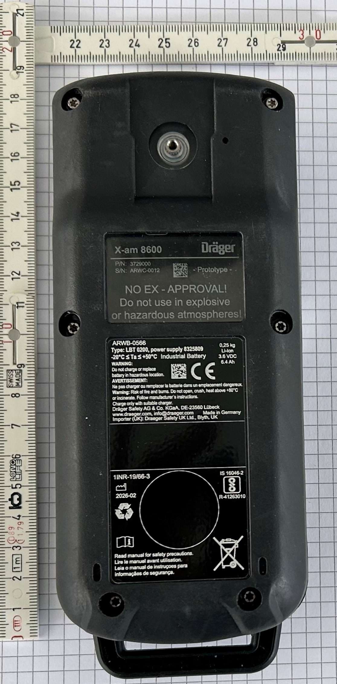
X6O-RF002
Jul 31, 2026Portable multi gas detector
Equipment Class
DXX - Part 15 Low Power Communication Device Transmitter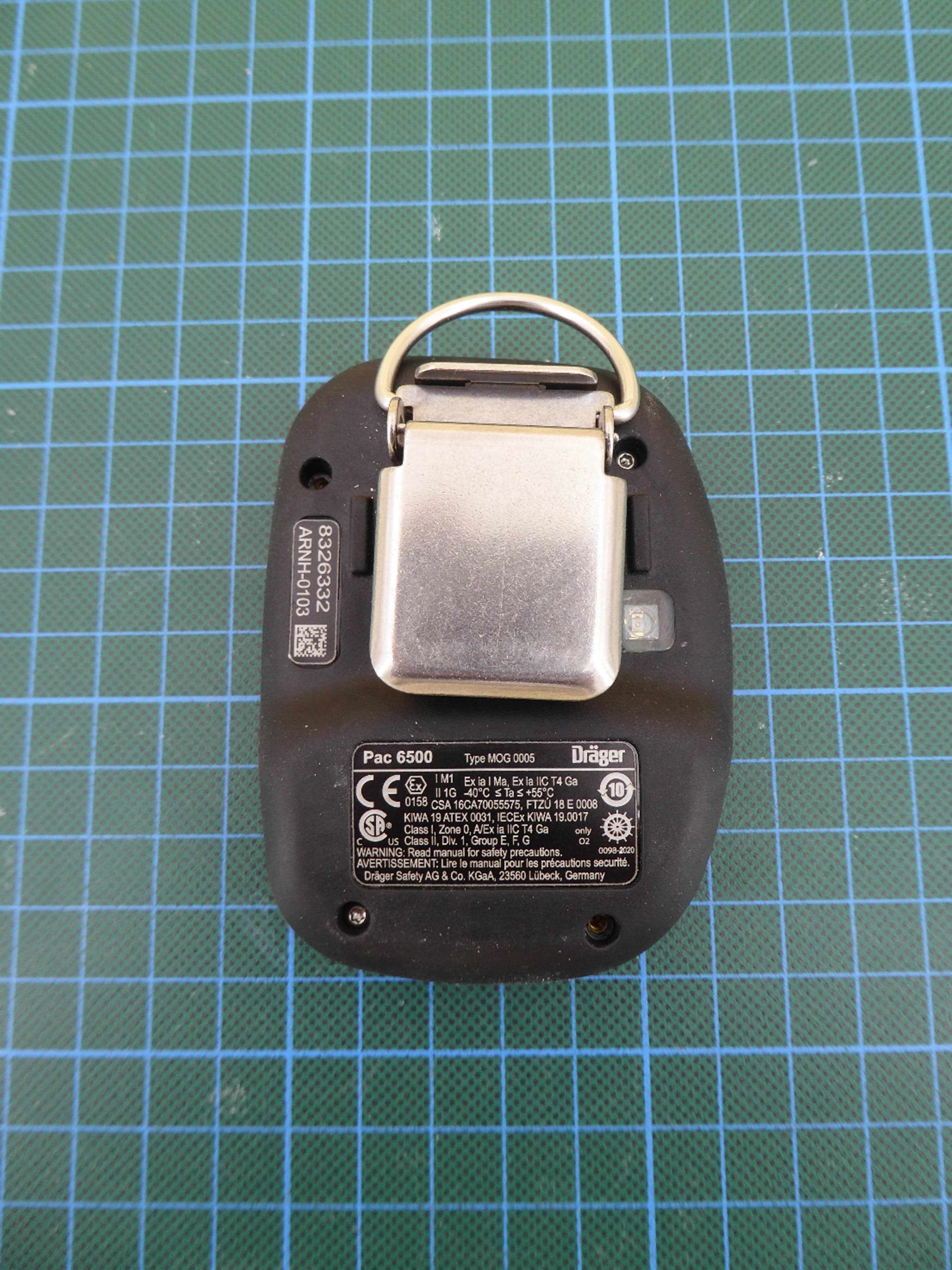
X6O-BT005
Feb 18, 2021Portable Single-Gas Monitor with BLE
Equipment Class
DTS - Digital Transmission System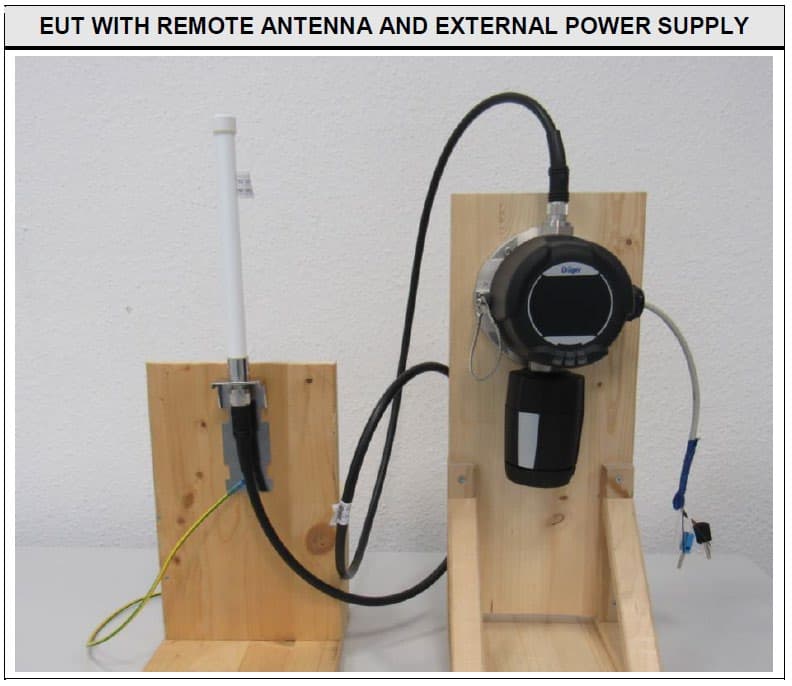
X6O-RC001
Feb 03, 2020gas measurement device / wireless
Equipment Class
DTS - Digital Transmission System