X6ZRP24RA9D2.4GHz RADIO CONTROL
Nextlink Co., Ltd.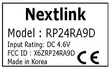
Click to zoom
Application Details
- Equipment Class
- DTS - Digital Transmission System
- Date of Grant
- Apr 06, 2010
- Application Purpose
- Original Equipment
- Date of Application
- Apr 06, 2010
- Equipment Note
- 2.4GHz RADIO CONTROL
- Frequency Range
- 2405.00000000 - 2480.00000000
- Company
- Nextlink Co., Ltd.
- Country
- South Korea
Documents & Files
Document Text
Text extracted from the exhibit documents filed with the FCC. Open a document above to read the original.
Users Manual
User's Manual Handbuch RF䊝䉳䊠䊷䊦䊶䊧䉲䊷䊋䊷ขᛒ⺑ᦠ RFβʨ / Ύչдӡٝԋύԅ * This user guide is subject to change without notice. RP24TD9 RP24TD9J RP24TD9M RP24RA4D RP24RA5D RP24RA6D RP24RA8D RP24RA9D Ver. 2.0 www.rcenjoy.com Tx 2.4GHz Radio Control Receiver &OHMJTI ڌڋ Introduction The existing 2.4GHz Radio Control and receivers cause inconvenience to RC users because of restricted frequency use, which comes from FM radio technology. Utilizing digital spectrum technology within the 2.4 GHz ISM band, the Radiopost RF System provides secure radio link, high transmission speed and superb resolution allowing the device to respond quickly and accurately without interference. The Radiopost Tx 2.4GHz Radio Control and receivers offer a significant advantage of eliminating the possibility of interference. Each Tx 2.4GHz Radio Control is programmed with a unique identification code to communicate with its specified receiver. Once the receiver is paired with the Tx 2.4GHz Radio Control (called ID Setting), the receiver will only take data from this specific radio controller where the Tx 2.4GHz Radio Control is equipped, ignoring signals from other sources. The Radiopost Tx 2.4GHz Radio Control and receivers scan and select the superior channels that are not being used to avoid collision in channels and data loss between the Tx 2.4GHz Radio Control and the receiver. This device complies with part 15 of the FCC rules. Operation is subject to the following two conditions: (1) this device may not cause harmful interference, and (2) this device must accept any interference received, including interference that may cause undesired operation. FCC Information &OHMJTI ڍڋ Precautions Read this manual before installation or use. Do not disassemble the Tx 2.4GHz Radio Control and the receiver because it may cause severe damage or problems. Install the Tx 2.4GHz Radio Control and the receiver after cutting off the power of the radio controller and RC models such as model aircrafts or helicopters or cars. The receiver should be turned on after the radio controller is switched on. When turning on the radio controller, be sure to put the throttle to the stop position. When switching off, make sure the engine or the motor of the RC models should be stopped. First, switch off the receiver thenthe radio controller. If this is not done in this order, it may cause temporary malfunctions. Prior to actual use and control of RC models, perform operation tests between the Tx 2.4GHz Radio Control and the receiver. If these tests fail, do not operate RC models. When installing the receiver in RC models, use impact protection materials to avoid damage to the receiver, which may be caused by the vibration of RC models or the impact from the outside. Do not alter length of antenna arbitrarily. The antenna should not be hidden by the RC model's main body or cover, coated with metallic paint or carbon fiber. Do not use Radiopost Tx 2.4GHz Radio Control and receivers together with Tx 2.4GHz Radio Control and receivers produced by other manufacturers. Do not operate the Tx module with two or more receivers. The receiver antenna shall be installed not to get affected by the magnetic field of power cables. * Nextlink will not be responsible for damage caused by use which is prohibited. 4BGFUZ $BVUJPO &OHMJTI ڎڋ Name of Each Part RP24TD9JRP24TD9 ID Setting Button ID Setting Button Status LED Status LED ID Setting Button Status LED RP24TD9M RP24RA4DRP24RA8DRP24RA9DRP24RA6DRP24RA5D [For JR radio controllers] [For Sanwa radio controllers] [For Futaba and Hitec radio controllers] www.rcenjoy.com Spread Spectrum 2.4GHz2.4GHz RF MODULE www.rcenjoy.com ID SETSTATUS RP24TD9J 2.4GHz2.4GHz RF MODULE ID SETSTATUS RP24TD9RP24TD9 www.rcenjoy.com AntennaAntenna Antenna Status LED ID Setting Button RP24RA6DRP24RA6D 2.4GHz2.4GHz 6CH Receiver ID SET ՙ՞Շՙ՞Ոՙ՞Չՙ՞Պՙ՞Ջ Յՙ՞Ռ www.rcenjoy.com Antenna Antenna Status LED ID Setting Button Failsafe Button RP24RA8DRP24RA8D 2.4GHz2.4GHz 8CH Receiver I D S E T F / S ՙ՞Շՙ՞Ոՙ՞Չ ՙ՞Պ ՙ՞Ջՙ՞Ռՙ՞Ս Յՙ՞Վ www.rcenjoy.com Antenna Status LED ID Setting Button Failsafe Button Status LED ID Setting Button ՙՇ ՙՈՙՉՙՊ ՅՙՋ 55 C h a n n e l R e c e i v e r www.rcenjoy.com 2.4GHz2.4GHz RP24RA5DRP24RA5D Antenna Status LED ID Setting Button Antenna ID SET 2.4GHz2.4GHz RP24RA4DRP24RA4D 44 ChannelChannel Tx 2.4GHz Radio Control Receiver &OHMJTI ڏڋ Tx Module Features High stability is guaranteed by using 2.4 GHz ISM bandwidth. Crystal is not necessary due to automatic channel selection. ID Setting is checked by beeping sounds. Binding speed is superior. The embedded Tx 2.4GHz Radio Control antenna provides convenience for users when the stand is attached to the radio controller. Radiopost Tx 2.4GHz Radio Control can be paired with any Radiopost receivers. It provides a wide range and high durability. It is a highly sensitive receiver which is less affected by intermodulation It is a universal type which can be used for model aircrafts,helicopters and cars. It is free from "NO CONTROL" after ID Setting. The Failsafe Function(only applied to RP24RA8D/ RP24RA9D) minimizes damage to RC models caused by accident. Receiver &OHMJTI ڐڋ LED Status by Function When powered on for the first time, the white LED blinks. When ID Setting button is pressed, the white LED blinks faster than previously. When ID Setting is done, the LED turns green and remains still. The white LED blinks slowly if there is no data transferred from the Tx 2.4GHz Radio Control LED turns green White LED blinks slowly White LED blinks Power Tx Module Red LED blinks Receiver Green LED blinks. Green color remains still White LED blinks faster When powered on for the first time, the green LED blinks turning into the receiver searching status. When ID Setting button is pressed, it turns into ID-Setting mode and the red LED blinks. When ID Setting is done, the LED turns green and the green color remains still. &OHMJTI ڑڋ Installation Instructions White LED blinks Power Choose a Tx 2.4GHz Radio Co…
Text truncated - open the document above for the full version.
Cover Letter(s)
Nextlink Co., Ltd. E-Mail : [email protected] Tel. : 82-31-732-6441 Fax. : 82-31-732-6442 March 23, 2010 Federal Communications Commission Authorization and Evaluation Division Confidentiality Request regarding application for certification of FCC ID: X6ZRP24RA9D Pursuant to Sections 0.457 and 0.459 of the Commission’s Rules, we hereby request confidential treatment of information accompanying this application as outlined below: Exhibit Type File Name Block Diagram CONF APPENDIX X6ZRP24RA9D BLK DIA.PDF Schematics Diagram(s) CONF APPENDIX X6ZRP24RA9D SCH DIA.PDF Circuit Description CONF APPENDIX X6ZRP24RA9D CIRCUIT DESC.PDF The above materials contain trade secrets and proprietary information not customarily released to the public. The public disclosure of these materials may be harmful to the applicant and provide unjustified benefits to its competitors. The applicant understands that pursuant to Section 0.457 of the Rules, disclosure of this application and all accompanying documentation will not be made before the date of the Grant for this application. Sincerely, Jum-Su Kim/Manager
External Photos
www.kes.co.kr EUT External Photographs
ID Label/Location Info
www.kes.co.kr FCC ID label and Location LABLE
Internal Photos
www.kes.co.kr EUT Internal Photographs
Parts List/Tune Up Info
RP24RA9D 7 RP24RA9D Part List Item Reference Qty Part Name Description VALUE 1 CON4 1 1.27mm_6pin_3X2 1.27mm_6pin_3X2 1.27mm_6pin_3X2 2 CON3 1 1.27mm_6pin_3X2 1.27mm_6pin_3X2 1.27mm_6pin_3X2 3 ANT 1 2.45GHz ANTTENA WIRE_ANT2.45_ANT 2.4GHz 4 U2 1 8-Bit Microcontroller (MCU) AVR MCU ATmega48V-10MU (MLF 32M1-A) MEGA48V 5 CON1 1 CHANNEL 7 6 FL1 1 2.4GHz Band Pass Filter DWF2R2440G04 DWF-244 7 U1 1 MG2455-F48 MG2455-F48 QFN48 MG2455-F48 8 BL3 1 LDB15C101A2400 LDB212G4010C-001 Balun(100ohm) 9 C3, C4, C8, C15 4 C1005COG104J050T050D GRM155R71C104KA88D 0.1uF 10 C12, C25 2 C1005COG103J050T050D GRM155R71C103KA01D 10nF 11 C2, C9, C14, C18, C19, C31 6 C1005COG100J050T050D GRM1555C1H100JZ01D 10pF 12 C6, C7 2 C1005COG130J050T050D GRM1555C1H130JZ01D 13pF 13 C36 1 C1005COG153J050T050D GRM155R71C153KA01D 15nF 14 C1, C5 2 C1005COG180J050T050D GRM155C1H180JZ01D 18pF 15 C20, C21, C23, C24, C30, C32, C33, C34, C37 9 C1005COG221J050T050D GRM1555C1H221JZ01D 220pF 16 C29 1 C1005COG8R2J050T050D GRM155C1H8R2JZ01D 8.2pF 17 L2, L3 2 82nH +-5% LQG15HS82NJ02D 82nH 18 R8, R9, R10, R13, R14, R15, R16, R18, R19 9 CR0402 471R 5% 470ohm REEL CR020471J002 470 19 R1, R11, R20 3 CR0402 103R 5% 10Kohm REEL CR020103J002 10K 20 R3 1 CR0402 154R 5% 150Kohm REEL CR020154J002 150K 21 R21, R4, R5 3 CR0402 221R 5% 220ohm REEL CR020221J002 220 22 R17 1 CR0402 823R 5% 82Kohm REEL CR020823J002 82K 23 C11, C13 2 GRM188R60J106ME47D GRM39-035 X5R 106M 6.3V 10uF/6.3V 24 L1 1 LG HK 1608 3N9S-T LG HK 1608 3N9S-T 3.9nH 25 LED3 1 1608 Pure Green TG102 P-GREEN 26 LED2 1 1608 RED IWS-165-RXWF RED 27 LED1 1 1608 WHITE TWH104-H WHITE 28 C16, C17 2 CAP TANTAL 227/6.3 3527 CAP TANTAL 227/6.3 3527 220uF/6.3V 29 C10 1 CAP TANTAL 336/16V 3527 CAP TANTAL 336/16V 3527 33uF/16V 30 SW2 1 SKRE (RA) Side push (RA) FALE SAFE 31 SW1 1 SKQM (ST) Top push (ST) ID SET 32 SD3 1 Schottky Diode 1.5A SMF SMFB23L-RTK/P SMFB23L 33 U3 1 ELM 7527XB SOT23 ELM7527XB ELM7527XB 34 X2 1 16MHz FL160003 16MHz FL160003 10PPM 16.000MHz 35 C35 1 CAP TANTAL 105/10V 2012 TCSCN1A2012KPAR 10uF/10V 36 U4 1 XC6202 SOT-89 REEL XC6202P332PR 3.3V/150mA 37 X3 1 7.3728MHz GX-750 7.3728MHz GX-750 7.3728MHz
Test Report
www.kes.co.kr Te s t Re p o r t N o. : TK-FR10010 Model No: RP24RA9D Applicant: Nextlink Co., Ltd. Page 1 of 28 This Report shall not be reproduced except in full without the written approval of THRU KES CO.,LTD. TEST REPORT For FCC Test Report No. : TK-FR10010 Date of Issue : 04/06/2010 Description of Product : 2.4GHz Radio Control Model No. : RP24RA9D Applicant : Nextlink Co., Ltd. 701, Jungang Induspia II #144-5 Sangdaewon-dong, Jungwon-gu Seongnam-si,Gyeonhgi-do Manufacturer : Nextlink Co., Ltd. 701, Jungang Induspia II #144-5 Sangdaewon-dong, Jungwon-gu Seongnam-si,Gyeonhgi-do Standards : FCC Part 15 Subpart C §15.247 Test Date : 03/23/2010 ~ 04/06/2010 Test Results : PASS FAIL The test results relate only to the items tested. Tested by: Reviewed by: Kyu-Chul Shin KT Kang Test Engineer Technical Manager Date:04/06/2010 Date: 04/06/2010 THRU-KES CO.,LTD. 477-6, Hager-Ri, Yoju-Up, Yoju-Gun Kyunggi-Do,469-803, Korea Tel: +82-31-425-6200 / Fax: +82-31-424-0450 www.kes.co.kr Te s t Re p o r t N o. : TK-FR10010 Model No: RP24RA9D Applicant: Nextlink Co., Ltd. Page 2 of 28 This Report shall not be reproduced except in full without the written approval of THRU KES CO.,LTD. TABLE OF CONTENTS 1.0 General Product Description ...............................................................................3 1.1 Tested Frequency .............................................................................................3 1.2 Model Differences .............................................................................................4 1.3 Device Modifications .........................................................................................4 1.4 Peripheral Devices ............................................................................................4 1.5 Calibration Details of Equipment Used for Measurement .........................................5 1.6 Test Facility(4769B-1) .......................................................................................5 2.0 Summary of tests .............................................................................................6 2.1 Technical Characteristic Test .....................................................................................7 2.1.1 6dB Bandwidth - 15.247(a) ..........................................................................7 2.1.2 Maximum peak Conducted Output Power-15.247(b) ...................................... 10 2.1.3 Power Spectral Density-15.247(e) ............................................................... 13 2.1.4 Band - edge -15.247(d) ........................................................................... 16 2.1.5 Field Strength of Emissions 15.209.............................................................. 21 2.1.6 AC Conducted Emissions 15.207 ................................................................. 26 APPENDIX A – Test Equipment Used For Tests ................................................................ 27 www.kes.co.kr Te s t Re p o r t N o. : TK-FR10010 Model No: RP24RA9D Applicant: Nextlink Co., Ltd. Page 3 of 28 This Report shall not be reproduced except in full without the written approval of THRU KES CO.,LTD. 1.0 General Product Description Equipment model name : RP24RA9D Serial number : Prototype EUT condition : Pre-production, not damaged Antenna type : Wire antenna Gain 1.83dBi Frequency Range : 2405MHz ~ 2480MHz RF output power : -9.12 dBm Peak Conducted Number of channels : 76 Channel Spacing : 1 MHz Power Source : DC 4.6V 1.1 Tested Frequency LOW MID HIGH Frequency (MHz) 2405 2440 2480 www.kes.co.kr Te s t Re p o r t N o. : TK-FR10010 Model No: RP24RA9D Applicant: Nextlink Co., Ltd. Page 4 of 28 This Report shall not be reproduced except in full without the written approval of THRU KES CO.,LTD. 1.2 Model Differences Not applicable 1.3 Device Modifications The following modifications were necessary for compliance: Not applicable 1.4 Peripheral Devices Device Manufacturer Model No. Serial No. FCC ID or DoC EUT Nextlink Co., Ltd. RP24RA9D - - Notebook FUJITSU LIMITED S6120 - DoC DC Power Supply HAN YOUNG ELECT. CO. HYP-3010D - - www.kes.co.kr Te s t Re p o r t N o. : TK-FR10010 Model No: RP24RA9D Applicant: Nextlink Co., Ltd. Page 5 of 28 This Report shall not be reproduced except in full without the written approval of THRU KES CO.,LTD. 1.5 Calibration Details of Equipment Used for Measurement Test equipment and test accessories are calibrated on regular basis. The maximum time between calibrations is one year or what is recommended by the manufacturer, whichever is less. All test equipment calibrations are traceable to the Korea Research Institute of Standards and Science (KRISS), therefore, all test data recorded in this report is traceable to KRISS. 1.6 Test Facility THRU-KES Co.,Ltd. (Test Site # : 343818) 477-6, Hager-Ri, Yoju-Up, Yoju-Gun Kyunggi-Do,469-803, Korea www.kes.co.kr Te s t Re p o r t N o. : TK-FR10010 Model No: RP24RA9D Applicant: Nextlink Co., Ltd. Page 6 of 28 This Report shall not be reproduced except in full without the written approval of THRU KES CO.,LTD. 2.0 Summary of tests FCC Part Section(s) Parameter Limit Test Condition Status (note 1) 15.247(a) 6 dB Bandwidth > 500kHz C 15.247(b) Transmitter Output Power < 1Watt C 15.247(d) Conducted Spurious emission > 20 dBc C 15.247(d) Band Edge > 20 dBc C C 15.247(e) Transmitter Power Spectral Density < 8dBm @ 3kHz Conducted C 15.209 Field Strength of Harmonics < 54 dBuV (at 3m) Radiated c 15.207 AC Conducted Emissions EN 55022 Line Conducted NA Note 1: C=Complies NC=Not Complies NT=Not Tested NA=Not Applicable Note 2: The data in this test report are traceable to the national or international standards. The sample was tested according to the following specification: - FCC Part 15.247, ANSI C63.4-2003 www.kes.co.kr Te s t Re p o r t N o. : TK-FR10010 Model No: RP24RA9D Applicant: Nextlink Co., Ltd. Page 7 of 28 This Report shall not be reproduced except in full without the written approval of…
Text truncated - open the document above for the full version.
Test Setup Photos
www.kes.co.kr Te s t Re p o r t N o. : TK-FR10010 Model No: RP24RA9D Applicant: Nextlink Co., Ltd. Page 28 of 28 This Report shall not be reproduced except in full without the written approval of THRU KES CO.,LTD. Test Setup Photos and Configuration Radiated Electric Field Emissions
Contact Information
Applicant
Kim Jum-Su
Test Firm
KES Co., Ltd.In-sung Ryu
Technical Specifications
| # | Rule Parts | Frequency Range | Power Output |
|---|---|---|---|
| 1 | 15C | 2.40 GHz - 2.48 GHz | 100.00 µW |
Other Applications from Nextlink Co., Ltd.

X6ZRP24RS5DX
Apr 22, 20122.4 GHz RADIO CONTROL
Equipment Class
DTS - Digital Transmission System
X6ZTS401
Dec 07, 20102.4GHz RADIO CONTROL
Equipment Class
DTS - Digital Transmission System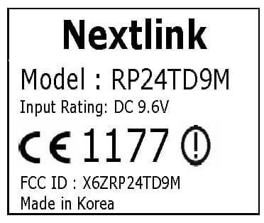
X6ZRP24TD9M
Apr 08, 20102.4GHz RADIO CONTROL
Equipment Class
DTS - Digital Transmission System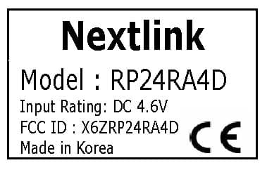
X6ZRP24RA4D
Apr 08, 20102.4GHz RADIO CONTROL
Equipment Class
DTS - Digital Transmission System