X6ZTS4012.4GHz RADIO CONTROL
Nextlink Co., Ltd.
Click to zoom
Application Details
- Equipment Class
- DTS - Digital Transmission System
- Date of Grant
- Dec 07, 2010
- Application Purpose
- Original Equipment
- Date of Application
- Dec 07, 2010
- Equipment Note
- 2.4GHz RADIO CONTROL
- Frequency Range
- 2405.00000000 - 2480.00000000
- Company
- Nextlink Co., Ltd.
- Country
- South Korea
Documents & Files
Document Text
Text extracted from the exhibit documents filed with the FCC. Open a document above to read the original.
Users Manual
User Manual for 4 Channel Transmitter TS401 2.4GHz 2 ■General Information Caution ☞It is prohibited to copy a part of or the whole of this manual. ☞Thecontentsofthemanualmaychangewithoutpriornotice. ☞Iftherearemistakesormissingpartsinthismanual,pleasecontactus. ☞In some cases, the manufacturer does not take responsibilities for the results which are brought upon by the customers. ■Compliance Information Statement (for U.S.A.) This device, trade name Radiopost, model number TS401, complies with part 15 of the FCC Rules. Operation is subject to the following two conditions: (1) This device may not cause harmful interference. (2) This device must accept any interference received, including interference that may cause undesired operation. ThankyouforpurchasingtheRadiopostTS4012.4GHz.Theuniquefeaturesof thisproductareintroducedinthismanual.Pleasereadtheinstructionmanual carefullyandthoroughlyforoptimalenjoymentandcontrol. ThisRCsystemoperateswithadirectconnectionbetweenthetransmitterand itsreceiver,usinga2.4GHzdigitalfrequencyband.Asotherstransmittersmay usevariousfrequenciesoracrystaltypeFMband,Radiopost‟sTS4012.4GHz systemisfreefrominterferencetorespondmorequicklyandaccurately. RadiopostTS4012.4GHzisdesignedforallkindsofRCcarsandboats. Whetheritison-roadoroff-road,atapondorlake,Radiopost‟sproductsare madeforvariousRChobbyists.Frombeginnerstoexperts,Radiopostwishes youthebestasyousetforthintotheRCworldwithourspecializedproducts. ▶TS4012.4GHzisahighpoweredRCsystem.Pleasecheckthemaximum coveragedistanceandoperationrangeforyoursafety. ▶The2.4GHzisanISMbandthatcanbeusedfordevicesorequipments otherthanRChobbymodels.Theuseofdifferentproductsinthesame 2.4GHzbandwidthmaycausefrequencyinterferencesamongtheproducts. So,beforeyoustart,checktoseeiftheservosmoveproperlyandother connections,byperformingatestrunfromthefurthestdistancepossible. ▶Asvariousmanufacturersandproductsmayhavedifferent2.4GHz technology,onlytheRadiopostreceiversbindwiththeTS401. 3 ■Safety ■Precautions & Warnings ▣Precautions in Application, Export and Modification BeforeusingtheTS4012.4GHzsystem,pleasecarefullyandthoroughlyread thismanualinordertouseyourRCsystemsafely. Usethisproductinasafemanner,observingallsafetyprecautionsatall times. Pleasefollowandobservealladditionalrulesattheplaceofoperationas suggested(i.e.racetracks,lakes,etc.)orwhereveryouusetheRCsystem. IftheRCmodelisnotrunningproperly,pleaseimmediatelystopallcontrols. DonotruntheRCmodelbeforecompletelyfixingtheproblems. TheRCmodelyouusemaycauseinjuriesordamages.Pleasealwaysbe carefulwhenrunningtheRCsystemandmodels. Waterormoisturemaycausemalfunctionstothesystem.Pleasekeepthe RCsystemawayfromwaterandmoisture. FortheRCboat,pleaseinstallthereceiverandservointhewaterproofbox. IfyouareabeginnertotheRChobby,westronglyrecommendthatyou seektheadviceofexpertswhocanassistyouorcontactyourlocalRC hobbyshop. ▶(Application) Do not use the transmitter for non-RC models. This product is not designed and intended for use in any application other than the radio control models for hobby and recreational purposes. ▶(Export precautions) When this product is exported from the country of manufacturer, its use is to be approved by the laws governing the country of destination for the devices emitting radio frequency. If this product is then re-exported to other countries, it may be subject to restrictions on such export. Prior approval of the appropriate government authorities may be required. If you have purchased this product from an exporter outside your country and not an authorized Radiopost 4 ▣Precautions for the Transmitter ▣Precautions for the Receiver distributors or dealer in your country, please immediately contact the seller to determine if such export regulations have been met. Use of this product with other than models may be restricted by the export and trade control regulations and an application for export approval must be submitted. ▶(Modifications, Adjustment and Replacement of Parts) Radiopost is not responsible for the unauthorized modification, adjustment and replacement of parts on this product. Any such changes may void any or all warranties associated with this product. ▶To start, first switch on the transmitter and secondly, the receiver. After using the RC Model, please switch off the receiver first and then the transmitter. Reversing the order of powering on and off may cause critical damages to the devices or persons. ▶Please check if the batteries for transmitter and receiver are fully charged before starting. ▶The antenna for Radiopost‟s transmitter TS450 2.4GHz is built-in the product (Internal). The antenna in located underneath the front top section, above the power switch of the transmitter. Be careful not to cover this part of transmitter, as it may cause weak signal output if covered. ▶The receiver antenna is made of coaxial cable that consists of a covered part and naked wire part. The naked wire is used to receive the radio wave. Be careful not to bend the naked part of the wire, as it also may weaken the signal quality of the receiver. ▶An antenna cable is very delicate. Please handle it with care. ▶Do not forcibly pull the antenna cable. ▶Do not cut or link the antenna cable with other wires. 5 ▶Do not drive the models on rainy days, on damp or humid days and or at night. If the product(s) come in contact with water, malfunctions may occur to the transmitter and the model and may cause the systems be out of control. Warning ▶Covered part of the antenna may be slightly made into a smooth curve. But do not fully bend it repeatedly or too sharply, which may cause unexpected problems with the antenna. ▶The antenna must be installed in the plastic tube or antenna pipe to stand upright according to the RC model assembly instruction. It is highly recommended to mount the antenna of receiver away from the motor, the battery and the speed controller. ▶If the connector of receiver shakes, an unexpected outcome may occur during controlling. Please check if …
Text truncated - open the document above for the full version.
Cover Letter(s)
Nextlink Co., Ltd. E-Mail : [email protected] Tel. : 82-31-732-6441 Fax. : 82-31-732-6442 December 06, 2010 Federal Communications Commission Authorization and Evaluation Division Confidentiality Request regarding application for certification of FCC ID: X6ZTS401 Pursuant to Sections 0.457 and 0.459 of the Commission’s Rules, we hereby request confidential treatment of information accompanying this application as outlined below: Exhibit Type File Name Part List CONF APPENDIX – TS401 - Part List.PDF Schematics Diagram(s) CONF APPENDIX – TS401 – Schemetics.PDF Block diagram CONF APPENDIX – TS401 – Block diagram.PDF The above materials contain trade secrets and proprietary information not customarily released to the public. The public disclosure of these materials may be harmful to the applicant and provide unjustified benefits to its competitors. The applicant understands that pursuant to Section 0.457 of the Rules, disclosure of this application and all accompanying documentation will not be made before the date of the Grant for this application. Sincerely, Jum-Su Kim/Manager
External Photos
www.kes.co.kr EUT External Photographs
ID Label/Location Info
www.kes.co.kr FCC ID label and Location LABLE
Internal Photos
www.kes.co.kr EUT Internal Photographs www.kes.co.kr www.kes.co.kr www.kes.co.kr www.kes.co.kr www.kes.co.kr www.kes.co.kr ANT
Operational Description
MG2455-F48 Datasheet VER.1.0 The reproduction of this datasheet is NOT allowed without approval of RadioPulse Inc. All information and data contained in this datasheet are subject to change without notice. This publication supersedes and replaces all information previously supplied. RadioPulse Inc. has no responsibility to the consequence of using the patents describes in this document. MG2455-F48-D-001 MG2455-F48 Datasheet VER.1.0 Page:2/173 www.radiopulse.co.kr REVISION HISTORY Version Date Description VER.1.0 2007.10.1 First Official Version Release. MG2455-F48-D-001 MG2455-F48 Datasheet VER.1.0 Page:3/173 www.radiopulse.co.kr CONTENTS 1. INTRODUCTION ............................................................................................... 7 2. APPLICATIONS ................................................................................................ 7 3. ENHANCED FEATURES .................................................................................. 8 4. FEATURES ........................................................................................................ 8 5. PIN DESCRIPTION ......................................................................................... 10 6. APPLICATION CIRCUIT ................................................................................. 14 7. FUNCTIONAL DESCRIPTION ........................................................................ 17 7.1. MEMORY ORGANIZATION ....................................................................... 19 7.1.1. PROGRAM MEMORY ........................................................................ 19 7.1.2. DATA MEMORY .................................................................................. 21 7.1.3. GENERAL FUNCTION REGISTERS ................................................. 22 7.1.4. SPECIAL FUNCTION REGISTERS ................................................... 23 7.2. RESET ........................................................................................................ 35 7.3. CLOCK SOURCE ....................................................................................... 35 7.4. INTERRUPT SCHEME ............................................................................... 35 7.5. POWER MANAGEMENT ........................................................................... 41 7.6. ON-CHIP PERIPHERALS .......................................................................... 43 7.6.1. TIMER 0/1 .......................................................................................... 44 7.6.2. TIMER 2/3, PWN 2/3 .......................................................................... 49 7.6.3. WATCHDOG TIMER .......................................................................... 51 7.6.4. SLEEP TIMER .................................................................................... 52 7.6.5. INTERNAL RC OSCILLATOR ............................................................ 54 7.6.6. UART0/1 ............................................................................................. 54 7.6.7. SPI MASTER/SLAVE ......................................................................... 63 7.6.8. VOICE ................................................................................................ 68 7.6.9. RANDOM NUMBER GENERATOR (RNG) ........................................ 88 7.6.10. QUAD DECODER .............................................................................. 91 7.6.11. INTERNAL VOLTAGE REGULATOR ................................................. 94 7.6.12. 4-CHANNEL 8-BIT SENSOR ADC ..................................................... 94 7.6.13. ON-CHIP POWER-ON RESET .......................................................... 97 MG2455-F48-D-001 MG2455-F48 Datasheet VER.1.0 Page:4/173 www.radiopulse.co.kr 7.6.14. TEMPERATURE SENSOR ................................................................ 97 7.6.15. BATTERY MONITORING ................................................................... 98 7.7. MAC ............................................................................................................ 99 7.7.1. RECEIVED MODE ........................................................................... 101 7.7.2. TRANSMIT MODE ........................................................................... 102 7.7.3. DATA ENCRYPTION AND DECRYPTION ....................................... 103 7.8. PHY........................................................................................................... 115 7.8.1. INTERRUPT ..................................................................................... 118 7.8.2. REGISTERS ..................................................................................... 119 7.9. IN-SYSTEM PROGRAMMING(ISP) ......................................................... 154 7.10. MG2455 INSTRUCTION SET SUMMARY ............................................... 155 8. ABSOLUTE MAXIMUMRATINGS ................................................................ 158 9. DC CHARACTERISTICS .............................................................................. 159 10. ELECTRICAL SPECIFICATIONS ................................................................. 160 11. DIGITAL I/O ................................................................................................... 164 12. AC CHARACTERISTIC ................................................................................ 165 13. PACKAGE INFORMATION ........................................................................... 167 13.1. TRAY SPECIFICATION ............................................................................ 169 13.2. CARRIER TAPE AND REEL SPECIFICATION ........................................ 170 14. ORDERING INFORMATION ......................................................................... 171 MG2455-F48-D-001 MG2455-F48 Datasheet VER.1.0 Page:5/173 www.radiopulse.co.kr FIGURES FIGURE 1. PINOUT TOP VIEW OF MG2455-F48(EXPOSED PAD 48-…
Text truncated - open the document above for the full version.
RF Exposure Info
www.kes.co.kr Page 1 of 2 RF EXPOSURE EVALUATION Applicant : Nextlink Co., Ltd. Applicant Address : 701, Jungang Induspia II #144-5 Sangdaewon-dong, Jungwon-gu Seongnam-si, Gyeonhgi-do Kind of Product : 2.4GHz Radio Control Equipment model name : TS401 Antenna type : Patch antenna Gain: 2.97dBi Frequency Range : 2405 ~ 2480 MHz Number of channels : 76 Channel Spacing : 1 MHz www.kes.co.kr Page 2 of 2 ** MPE Calculations ** The EUT will only be used with a separation of 20 centimeters or greater between the antenna and the body of the user. The MPE calculation for this exposure is shown below. The peak radiated output power (EIRP) is calculated as follows: EIRP = P + G EIRP = 25.62 dBm Where, P = Power input to the antenna (mW) G = Power gain of the antenna (dBi) The numeric gain(G) of the antenna with a gain specified in dB is determined by: G = Log -1 (dB antenna gain / 10) G = Log -1 (2.97/ 10) G = 1.98 Power density at the specific separation: S = PG/(4R 2 π) S = (22.65 * 1.98 / (4 * 20 2 * π) S = 0.0726 mW/cm 2 Where, S = Maximum power density (mW/cm 2 ) P = Power input to the antenna (mW) G = Numeric power gain of the antenna R = Distance to the center of the radiation of the antenna (20cm = limit for MPE) The Maximum permissible exposure (MPE) for the general population is 1 mW/cm 2 . The power density at 20cm does not exceed the 1 mW/cm 2 limit. Estimated safe separation: R = √(PG / 4π) R = √(22.65 * 1.98/ 4π) R = 5.39 cm Where, P = Power input to the antenna (mW) G = Numeric power gain of the antenna R = Distance to the center of the radiation of the antenna (20cm = limit for MPE)
Test Report
www.kes.co.kr Te s t Re p o r t N o. : TK-FR10048 Model No: TS401 Applicant: Nextlink Co., Ltd. Page 1 of 28 This Report shall not be reproduced except in full without the written approval of THRU KES CO.,LTD. TEST REPORT For FCC Test Report No. : TK-FR10048 Date of Issue : 12/06/2010 Description of Product : 2.4GHz Radio Control Model No. : TS401 Applicant : Nextlink Co., Ltd. 701, Jungang Induspia II #144-5 Sangdaewon-dong, Jungwon-gu Seongnam-si,Gyeonhgi-do Manufacturer : Nextlink Co., Ltd. 701, Jungang Induspia II #144-5 Sangdaewon-dong, Jungwon-gu Seongnam-si,Gyeonhgi-do Standards : FCC Part 15 Subpart C §15.247 Test Date : 11/23/2010 ~ 12/06/2010 Test Results : PASS FAIL The test results relate only to the items tested. Tested by: Reviewed by: Kyu-Chul Shin KT Kang Test Engineer Technical Manager Date:12/06/2010 Date: 12/06/2010 THRU-KES CO.,LTD. 477-6, Hager-Ri, Yoju-Up, Yoju-Gun Kyunggi-Do,469-803, Korea Tel: +82-31-425-6200 / Fax: +82-31-424-0450 www.kes.co.kr Te s t Re p o r t N o. : TK-FR10048 Model No: TS401 Applicant: Nextlink Co., Ltd. Page 2 of 28 This Report shall not be reproduced except in full without the written approval of THRU KES CO.,LTD. TABLE OF CONTENTS 1.0 General Product Description ...............................................................................3 1.1 Tested Frequency .............................................................................................3 1.2 Model Differences .............................................................................................4 1.3 Device Modifications .........................................................................................4 1.4 Peripheral Devices ............................................................................................4 1.5 Calibration Details of Equipment Used for Measurement .........................................5 1.6 Test Facility(4769B-1) .......................................................................................5 2.0 Summary of tests .............................................................................................6 2.1 Technical Characteristic Test .....................................................................................7 2.1.1 6dB Bandwidth - 15.247(a) ..........................................................................7 2.1.2 Maximum peak Conducted Output Power-15.247(b) ...................................... 10 2.1.3 Power Spectral Density-15.247(e) ............................................................... 13 2.1.4 Band - edge -15.247(d) ........................................................................... 16 2.1.5 Field Strength of Emissions 15.209.............................................................. 21 2.1.6 AC Conducted Emissions 15.207 ................................................................. 26 APPENDIX A – Test Equipment Used For Tests ................................................................ 27 www.kes.co.kr Te s t Re p o r t N o. : TK-FR10048 Model No: TS401 Applicant: Nextlink Co., Ltd. Page 3 of 28 This Report shall not be reproduced except in full without the written approval of THRU KES CO.,LTD. 1.0 General Product Description Equipment model name : TS401 Serial number : Prototype EUT condition : Pre-production, not damaged Antenna type : Patch antenna Gain 2.97dBi Frequency Range : 2405MHz ~ 2480MHz RF output power : 22.65 dBm Peak Conducted Number of channels : 76 Channel Spacing : 1 MHz Power Source : DC 6V 1.1 Tested Frequency LOW MID HIGH Frequency (MHz) 2405 2440 2480 www.kes.co.kr Te s t Re p o r t N o. : TK-FR10048 Model No: TS401 Applicant: Nextlink Co., Ltd. Page 4 of 28 This Report shall not be reproduced except in full without the written approval of THRU KES CO.,LTD. 1.2 Model Differences Not applicable 1.3 Device Modifications The following modifications were necessary for compliance: Not applicable 1.4 Peripheral Devices Device Manufacturer Model No. Serial No. FCC ID or DoC EUT Nextlink Co., Ltd. TS401 - - Notebook FUJITSU LIMITED S6120 - DoC DC Power Supply HAN YOUNG ELECT. CO. HYP-3010D - - www.kes.co.kr Te s t Re p o r t N o. : TK-FR10048 Model No: TS401 Applicant: Nextlink Co., Ltd. Page 5 of 28 This Report shall not be reproduced except in full without the written approval of THRU KES CO.,LTD. 1.5 Calibration Details of Equipment Used for Measurement Test equipment and test accessories are calibrated on regular basis. The maximum time between calibrations is one year or what is recommended by the manufacturer, whichever is less. All test equipment calibrations are traceable to the Korea Research Institute of Standards and Science (KRISS), therefore, all test data recorded in this report is traceable to KRISS. 1.6 Test Facility THRU-KES Co.,Ltd. (Test Site # : 343818) 477-6, Hager-Ri, Yoju-Up, Yoju-Gun Kyunggi-Do,469-803, Korea www.kes.co.kr Te s t Re p o r t N o. : TK-FR10048 Model No: TS401 Applicant: Nextlink Co., Ltd. Page 6 of 28 This Report shall not be reproduced except in full without the written approval of THRU KES CO.,LTD. 2.0 Summary of tests FCC Part Section(s) Parameter Limit Test Condition Status (note 1) 15.247(a) 6 dB Bandwidth > 500kHz C 15.247(b) Transmitter Output Power < 1Watt C 15.247(d) Conducted Spurious emission > 20 dBc C 15.247(d) Band Edge > 20 dBc C C 15.247(e) Transmitter Power Spectral Density < 8dBm @ 3kHz Conducted C 15.209 Field Strength of Harmonics < 54 dBuV (at 3m) Radiated c 15.207 AC Conducted Emissions EN 55022 Line Conducted NA Note 1: C=Complies NC=Not Complies NT=Not Tested NA=Not Applicable Note 2: The data in this test report are traceable to the national or international standards. The sample was tested according to the following specification: - FCC Part 15.247, ANSI C63.4-2003 www.kes.co.kr Te s t Re p o r t N o. : TK-FR10048 Model No: TS401 Applicant: Nextlink Co., Ltd. Page 7 of 28 This Report shall not be reproduced except in full without the written approval of THRU KES CO.,LTD. 2.1 Technica…
Text truncated - open the document above for the full version.
Test Setup Photos
www.kes.co.kr Te s t Re p o r t N o. : TK-FR10048 Model No: TS401 Applicant: Nextlink Co., Ltd. Page 28 of 28 This Report shall not be reproduced except in full without the written approval of THRU KES CO.,LTD. Test Setup Photos and Configuration Radiated Electric Field Emissions
Contact Information
Applicant
Kim Jum-Su
Test Firm
KES Co., Ltd.In-sung Ryu
Technical Specifications
| # | Rule Parts | Frequency Range | Power Output |
|---|---|---|---|
| 1 | 15C | 2.40 GHz - 2.48 GHz | 184.00 mW |
Other Applications from Nextlink Co., Ltd.

X6ZRP24RS5DX
Apr 22, 20122.4 GHz RADIO CONTROL
Equipment Class
DTS - Digital Transmission System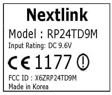
X6ZRP24TD9M
Apr 08, 20102.4GHz RADIO CONTROL
Equipment Class
DTS - Digital Transmission System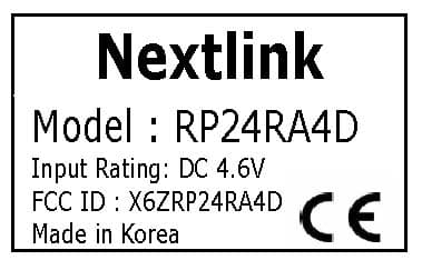
X6ZRP24RA4D
Apr 08, 20102.4GHz RADIO CONTROL
Equipment Class
DTS - Digital Transmission System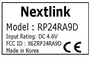
X6ZRP24RA9D
Apr 06, 20102.4GHz RADIO CONTROL
Equipment Class
DTS - Digital Transmission System