X78MU2NGProx II Mullion
Guardall, a division of CSG Security Corp
Click to zoom
Application Details
- Equipment Class
- DCD - Part 15 Low Power Transmitter Below 1705 kHz
- Date of Grant
- Aug 22, 2010
- Application Purpose
- Original Equipment
- Date of Application
- Aug 22, 2010
- Equipment Note
- GProx II Mullion
- Frequency Range
- 0.12000000 - 0.12000000
- Country
- Canada
Documents & Files
Document Text
Text extracted from the exhibit documents filed with the FCC. Open a document above to read the original.
Users Manual
22-0369v1.7 G-PROX / G-PROX II INSTALLATION REFERENCE CSG Security Corp / Sécurité CSG Corp Page 1 of 3 GUARDALL 5201 Explorer Drive, Mississauga, Ont., Canada. L4W-4H1 [email protected] +1 905.206.8434 | support@ guardall.com +1 905.206.8436 | Fax: +1 905.629.4970 www.guardall.com | +1 877.249.9993 These instructions provide a quick reference for installing the G-Prox II™ family of intelligent (jumper-free) proximity readers, and the G-Prox series I (HID™- compatible readers). These units are weather-resistant, and the G-Prox II™ readers are auto-programmable using special programming cards. These readers can be used with any type of door controller that supports standard Wiegand readers (with 12 V DC output). The arming station is supported by Monitor ISM/AFx systems. Cards : G-Prox II readers = G-Prox cards; G-Prox series I = HID comp. prox. cards. Switch-plate Reader 111-82x4 Mullion Reader 111-8289 Arming Station 111- 82x0 Mullion Arming Station 111-8267 Switch-plate Keypad 111-82x1 (Weigand) 111-82x3 (Matrix) Mullion Keypad 111-8266 Poducts Mullion Part Numbers: 111-8266, 111-8267, 111-8289. White Grey Black GProx I 111-8220 111-8240 111-8310 GProx I 111-8221 111-8241 111-8311 GProx I 111-8223 111-8243 111-8313 GProx I 111-8224 111-8244 111-8314 GProx II 111-8270 111-8280 111-8290 GProx II 111-8271 111-8281 111-8291 GProx II 111-8273 111-8283 111-8293 GProx II 111-8274 111-8284 111-8294 System Cabling Reference Recommended reader cabling is 24 AWG, shielded. (max 150 m / 500 feet). For reliable operation at max. distance, reader cabling must be less than 27 pf per foot. Number of Conductors Needed: Typically 6 conductors. Will need one or two more wires for external buzzer control (if supported). Check the wiring tables to verify the number of conductors. Note: A G-Prox II™ reader with Matrix-style keypad requires a second cable with the same specifications (8 conductors needed). Max. length: up to 150 m / 500 feet. These can be used with a door controller that supports a Wiegand reader with matrix keypad. !!! Do's & Don’ts !!! Notice: Do all wiring with the door controller powered down, or ensure the +12V is never connected without the 0V/Gnd first. • Static can destroy electronic components! Always take proper precautions when handling or transporting devices. • Remove power before servicing readers or other electronic components. • Always conform to local fire and building regulations (if unsure, find out). Specifications • Environment: -35 to 66° C (-31 to 151° F), 5-95% relative humidity (non-condensing) at 25° C (77° F). Weather resistant. • Power: 12 V DC (or 13.8 V) regulated, @100 mA (typical); • Data Output: Standard Wiegand; Cable Routing • Be sure to distance all cables from sources of electromagnetic interference (motors, fluorescent lights, etc.). Grounding • Ground the reader cable shield only at the door controller earth ground. G-Prox Series I DIP Switches G-Prox series I readers have DIP switches accessible from the back. (Set switches only when powered down.) (9 = factory default) Switch 1 ON = High Volume 9 OFF = Low Volume Switch 2 ON = Buzzer (+) trigger OFF = Buzzer Gnd trigger 9 Switch 3 ON = Pull Up on Data Lines OFF = No Pull Up 9 Switch 4 ON = No Beep on key press OFF = Beep on key press 9 Switch 5 ON = No Beep on Card Read OFF = Beep on Card Read 9 Switch 6 ON = No Flash on Card Read OFF = Flash on Card Read 9 Switch 7 ON = Red if both LED lines on OFF = Green if both lines on 9 Switch 8 ON = Dual LED Mode OFF = Single LED Mode 9 G-Prox II Programming These intelligent (jumper-free) readers are auto-programmable using special cards. Supported features include: • Operation of the door state LED; • How a 'card read' will be indicated; • The type of circuit to be used with the reader buzzer (active high vs. Gnd.); • Whether cards must be encoded with a specific lock code. For details on the programming cards, refer to "G-Prox II Programming" (pg. 2), plus the on-line help or User's Guide for the G-Prox Desktop Programming Station. Defaults: LED: Bi-colour; Keypress beep: Yes; Lock Code: 1 (card default); Buzz: Ground trigger; Card Read: LED & Beep. Cabling P/Ns: FT4 FT6 Module Bus (shielded) Preferred (24 AWG): 120-3401 120-3405 ULC (22 AWG): 120-3408 120-3409 Note: Max. distance may be reduced with the ULC cable. Reader cable (24 AWG shielded): 6 Conductors: 120-3402 120-3406 10 Conductors: 120-3403 120-3407 Note: ULC requires 22 AWG shielded cable. Power (18 AWG): 120-3400 120-3404 I/O (quad): 120-3410 120-3411 22-0369v1.7 G-PROX / G-PROX II INSTALLATION REFERENCE CSG Security Corp / Sécurité CSG Corp Page 2 of 3 GUARDALL 5201 Explorer Drive, Mississauga, Ont., Canada. L4W-4H1 [email protected] +1 905.206.8434 | support@ guardall.com +1 905.206.8436 | Fax: +1 905.629.4970 www.guardall.com | +1 877.249.9993 Reader Mounting: Standard readers can be surface mounted, or flush mounted. Flush Mount : Use the rear cover only as a template to mark the cut-out (L- shaped notches). Surface Mount : Use the rear cover for mounting onto the wall. The reader mounts onto the rear cover using the two self-tapping screws provided. Do NOT over tighten mounting screws. 6.5 cm 8.5 cm 2 3 9/16 11/32 Note: When selecting a mounting height, consider physically-challenged persons as well. Reader Wiring: Refer to the tables below when connecting your specific reader: Standard Reader and Arming Station Wiring: Notice: Do all wiring with the door controller powered down, or ensure the +12V is never connected without the 0V/Gnd first. Signal (Connect to) G-Prox II Reader G-Prox II Arming Station G-Prox Series I Reader (no keypad or matrix) G-Prox Series I w/ Wieg . keypad (rdr or Arm. Stn.) Your Wire Colour (Reader Extension Cable) Power (+V) Red Red Red Red Signal Gnd / 0V Black Black Black Black, Brown Data 0 Green Green Green Green Data 1 White White White White Red LED Brown Yellow Brown Blue Green LED Orange Orange Orange Orange Buzzer Output — — Blue — + trig. for buz. — Gre…
Text truncated - open the document above for the full version.
Cover Letter(s)
August 11, 2010 Ultratech Engineering Labs, Inc. 3000 Bristol Circle Oakville, Ontario L6H 6G4 Subject: Application for Equipment Authorization under FCC Part 15, Subpart C, Section 15.209 Applicant: Guardall, A Division of CSG Security Corp. Product: GProx II Mullion Reader Model No.: MU2N FCC ID: X78MU2N Dear Sir/Madam: As appointed agent for Guardall, A Division of CSG Security Corp., we submit this application for equipment authorization of the above product. Please review all required documents uploaded to your E-Filing Site. If you have any queries, please do not hesitate to contact us. Yours truly, Dan Huynh Dan Huynh Authorized Agent UltraTech Group of Labs FCC TCB & IC CB Ultratech’s Accreditations: 0685 FCC 91038 1309 46390-2049 NvLap Lab Code 200093-0 SL2-IN-E-1119R Korea KCC-RRL CA2049 3000 Bristol Circle, Oakville, Ontario, Canada L6H 6G4 Tel.: (905) 829-1570 Fax.: (905) 829-8050 Website: www.ultratech-labs.com Email: [email protected]
External Photos
MU2N Page 1 of 2 MU2N Page 2 of 2
ID Label/Location Info
452-8274 REV A Model:MU2N Guardall a division of CSG Security Corp. This device complies with Part 15 of the FCC rules. Operation is subject to the following two conditions: (1) This device may not cause harmful interference, and (2) this device must accept any interference received, including interference that may cause undesired operation. FCC ID: X78MU2N IC:8875A-MU2N www.guardall.com 3.15" (80.00mm) 0.394" (10.00mm) MU2N Page 1 of 1 FCC Label Location
Internal Photos
MU2N Page 1 of 4 Main PCB Front MU2N Page 2 of 4 Main PCB Back MU2N Page 3 of 4 Inside View without potting MU2N Page 4 of 4 Inside View Housing
Test Report
GProx II Mullion Reader Model No.: MU2N FCC ID: X78MU2N Applicant: Guardall, A Division of CSG Security Corp. 5201 Explorer Drive Mississauga, Ontario Canada L4W 4H1 In Accordance With Federal Communications Commission (FCC) Part 15, Subpart C, Section 15.209 UltraTech's File No.: CHB-119F15C209 This Test report is Issued under the Authority of Tri M. Luu, BASc Vice President of Engineering UltraTech Group of Labs Date: August 11, 2010 Report Prepared by: Dan Huynh Issued Date: August 11, 2010 Tested by: Hung Trinh, EMC/RFI Technician Satish Patel, EMC Technician Test Dates: March 9 & 11, 2010 The results in this Test Report apply only to the sample(s) tested, and the sample tested is randomly selected. This report must not be used by the client to claim product endorsement by NVLAP or any agency of the US Government. UltraTech 3000 Bristol Circle, Oakville, Ontario, Canada, L6H 6G4 Tel.: (905) 829-1570 Fax.: (905) 829-8050 Website: www.ultratech-labs.com , Email: [email protected], Email: [email protected] FCC Korea KCC-RRL 91038 1309 46390-2049 NvLap Lab Code 200093-0 SL2-IN-E-1119R CA2049 FCC Part 15, Subpart C, Section 15.209 GProx II Mullion Reader, Model No.: MU2N FCC ID: X78MU2N ULTRATECH GROUP OF LABS File #: CHB-119F15C209 3000 Bristol Circle, Oakville, Ontario, Canada L6H 6G4 August 11, 2010 Tel. #: 905-829-1570, Fax. #: 905-829-8050, Email: [email protected], Website: http://www.ultratech-labs.com All test results contained in this engineering test report are traceable to National Institute of Standards and Technology (NIST) TABLE OF CONTENTS EXHIBIT 1. INTRODUCTION.............................................................................................................................................. 1 1.1. SCOPE ........................................................................................................................................................................ 1 1.2. RELATED SUBMITTAL(S)/GRANT(S) ........................................................................................................................ 1 1.3. NORMATIVE REFERENCES ...................................................................................................................................... 1 EXHIBIT 2. PERFORMANCE ASSESSMENT.................................................................................................................... 2 2.1. CLIENT INFORMATION .............................................................................................................................................. 2 2.2. EQUIPMENT UNDER TEST (EUT) INFORMATION ................................................................................................... 2 2.3. EUT’S TECHNICAL SPECIFICATIONS....................................................................................................................... 3 2.4. LIST OF EUT’S PORTS............................................................................................................................................... 3 2.5. ANCILLARY EQUIPMENT ........................................................................................................................................... 4 2.6. TEST SETUP BLOCK DIAGRAM ................................................................................................................................ 5 EXHIBIT 3. EUT OPERATING CONDITIONS AND CONFIGURATIONS DURING TESTS............................................... 6 3.1. CLIMATE TEST CONDITIONS.................................................................................................................................... 6 3.2. OPERATIONAL TEST CONDITIONS & ARRANGEMENT FOR TESTS..................................................................... 6 EXHIBIT 4. SUMMARY OF TEST RESULTS ..................................................................................................................... 7 4.1. LOCATION OF TESTS ................................................................................................................................................ 7 4.2. APPLICABILITY & SUMMARY OF EMC EMISSION TEST RESULTS ....................................................................... 7 4.3. MODIFICATIONS INCORPORATED IN THE EUT FOR COMPLIANCE PURPOSES ................................................ 7 EXHIBIT 5. MEASUREMENTS, EXAMINATIONS & TEST DATA FOR EMC EMISSIONS ............................................... 8 5.1. TEST PROCEDURES.................................................................................................................................................. 8 5.2. MEASUREMENT UNCERTAINTIES ........................................................................................................................... 8 5.3. MEASUREMENT EQUIPMENT USED ........................................................................................................................ 8 5.4. ANTENNA REQUIREMENTS [47 CFR 15.203] ........................................................................................................... 8 5.5. POWERLINE CONDUCTED EMISSION [47 CFR 15.207(a)]...................................................................................... 9 5.6. TRANSMITTER RADIATED EMISSIONS [47 CFR §§ 15.209 & 15.205] ..................................................................12 5.7. 20 dB BANDWIDTH [47 CFR §§ 15.209 (a) & 15.205] .............................................................................................. 14 EXHIBIT 6. TEST EQUIPMENT LIST ............................................................................................................................... 16 EXHIBIT 7. MEASUREMENT UNCERTAINTY................................................................................................................. 17 7.1. LINE CONDUCTED EMISSION MEASUREMENT UNCERTAINTY ......................................................................... 17 7.2. R…
Text truncated - open the document above for the full version.
Test Setup Photos
ANNEX 1 - TEST SETUP PHOTOGRAPHS Guardall, A Division of CSG Security Corp GProx II Mullion Reader, Model MU2N FCC ID: X78MU2N A1 - 1 Power Line Conducted Emissions ANNEX 1 - TEST SETUP PHOTOGRAPHS Guardall, A Division of CSG Security Corp GProx II Mullion Reader, Model MU2N FCC ID: X78MU2N A1 - 2 Power Line Conducted Emissions ANNEX 1 - TEST SETUP PHOTOGRAPHS Guardall, A Division of CSG Security Corp GProx II Mullion Reader, Model MU2N FCC ID: X78MU2N A1 - 3 Radiated Emissions at 10m Distance (Orthogonal Position 1) ANNEX 1 - TEST SETUP PHOTOGRAPHS Guardall, A Division of CSG Security Corp GProx II Mullion Reader, Model MU2N FCC ID: X78MU2N A1 - 4 Radiated Emissions at 10m Distance (Orthogonal Position 1) ANNEX 1 - TEST SETUP PHOTOGRAPHS Guardall, A Division of CSG Security Corp GProx II Mullion Reader, Model MU2N FCC ID: X78MU2N A1 - 5 Radiated Emissions at 10m Distance (Orthogonal Position 2) ANNEX 1 - TEST SETUP PHOTOGRAPHS Guardall, A Division of CSG Security Corp GProx II Mullion Reader, Model MU2N FCC ID: X78MU2N A1 - 6 Radiated Emissions at 10m Distance (Orthogonal Position 3)
Contact Information
Applicant
George Grzeslo(Hardware Developer)
Technical Contact
UltraTech Engineering Labs Inc.Dan Huynh
[email protected]905-829-1570
3000 Bristol Circle · Oakville, ON · Canada
Test Firm
UltraTech Engineering Labs Inc.Tri Luu
Technical Specifications
| # | Rule Parts | Frequency Range | Power Output |
|---|---|---|---|
| 1 | 15C | 0.12 MHz - 0.12 MHz | - |
Other Applications from Guardall, a division of CSG Security Corp
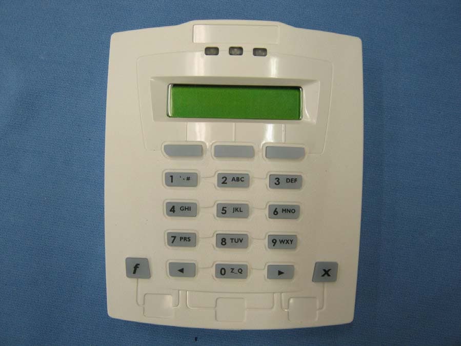
X78XLK1
Sep 22, 2010LCD Keypad
Equipment Class
DCD - Part 15 Low Power Transmitter Below 1705 kHz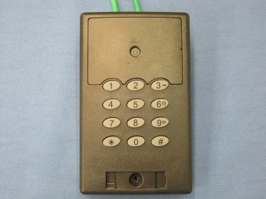
X78SP1M
Sep 19, 2010GProx I Switchplate Reader
Equipment Class
DCD - Part 15 Low Power Transmitter Below 1705 kHz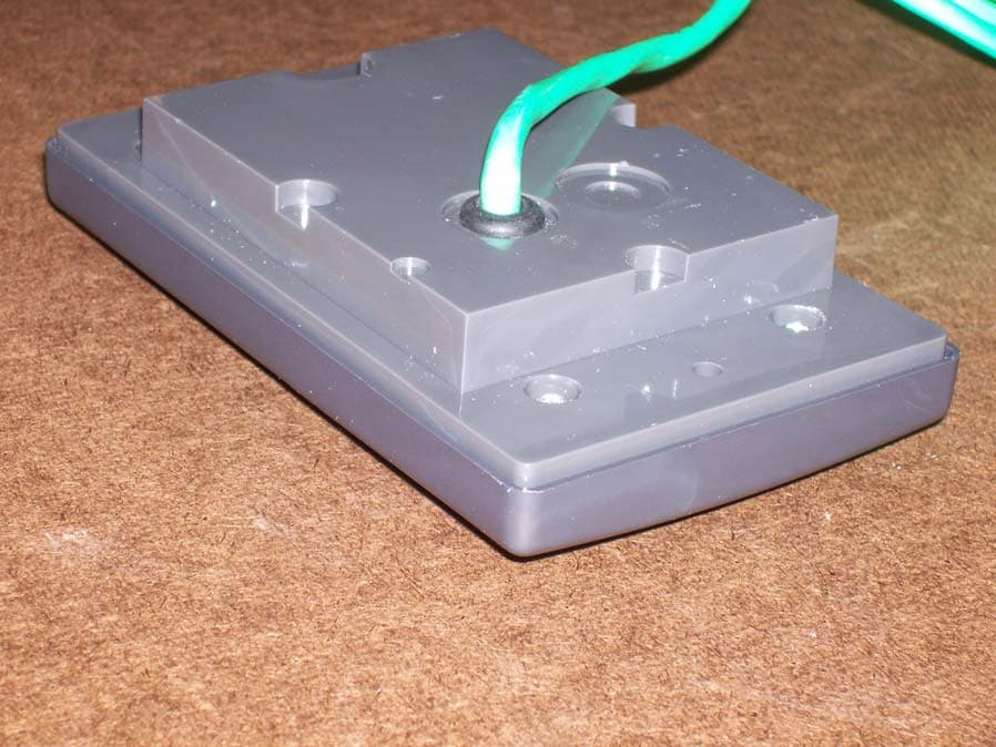
X78SP1A
Sep 19, 2010GProx I Switchplate Reader Keypad
Equipment Class
DCD - Part 15 Low Power Transmitter Below 1705 kHz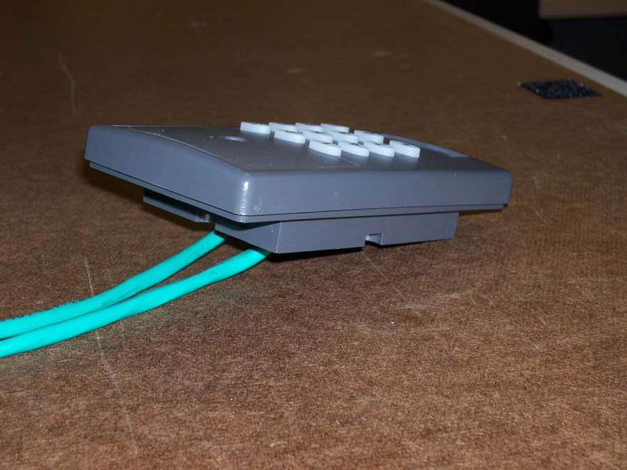
X78SP2M
Sep 06, 2010GProx II Switchplate Reader Keypad
Equipment Class
DCD - Part 15 Low Power Transmitter Below 1705 kHz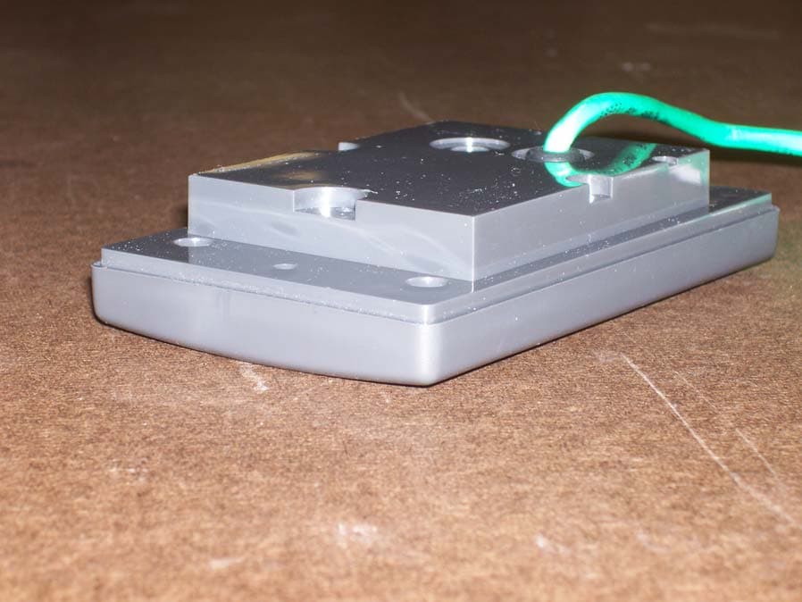
X78SP2N
Sep 06, 2010GProx II Switchplate Reader
Equipment Class
DCD - Part 15 Low Power Transmitter Below 1705 kHz