X8F-GT1Game Tracker
SkyHawke Technologies, LLC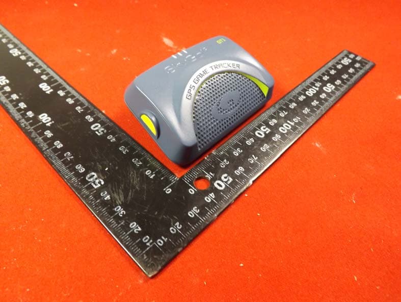
Click to zoom
Application Details
- Equipment Class
- DTS - Digital Transmission System
- Date of Grant
- May 17, 2015
- Application Purpose
- Original Equipment
- Date of Application
- May 17, 2015
- Equipment Note
- Game Tracker
- Frequency Range
- 2402.00000000 - 2480.00000000
- Company
- SkyHawke Technologies, LLC
- Country
- United States
Documents & Files
Document Text
Text extracted from the exhibit documents filed with the FCC. Open a document above to read the original.
Users Manual
V.1.0_022615US ©2015 SkyHawke Technologies, LLC. All rights reserved. SkyGolf ® , SkyCaddie ® , #1 Rangefinder in Golf ® , SkyGolf 360™, and SkyGolf GT1 TM are trademarks of SkyHawke Technologies, LLC. Apple ® and App Store SM are trademarks of Apple, Inc. Android ® and Google Play™ are trademarks of Google, Inc. The Bluetooth ® word mark and logos are registered trademarks owned by Bluetooth SIG, Inc. and any use of such marks by SkyHawke Technologies, LLC is under license. All other trademarks and copyrights are the property of their respective owners. U.S. Patent No. 5,740,077 and 5,844,483 & Patent Pending. For product terms and conditions, please visit www.skygolf.com SkyGolf GT1 ™ Wearable GPS and RFID Sensor Quick Start Guide 2 3 4 PRODUCT OVERVIEW Power Indicator Power Button SmartTag Read Area Micro USB Port GETTING STARTED SmartTag Read and Bluetooth ® Indicator GPS Indicator SkyGolf GT1 TM Wearable GPS and RFID Sensor IN THE BOX SkyGolf GT1 TM Wearable GPS/RFID Sensor SkyGolf GameTracker TM SmartTag Belt Clip USB Charging Cable User Documentation X1 3 5 4 GETTING STARTED Before using your new GT1 for the first time, complete the following steps to ensure your enjoyment during play: 1. Fully charge the battery of your GT1 2. Fully charge the battery of your smartphone 3. Logon to www.skygolf.com/gametracker on your smartphone and follow the onscreen instructions to: a. Download and install the SkyCaddie Mobile TM GPS Rangefinder app from your favorite app store. b. Register your new GT1 at www.skygolf.com/register Belt Clip NOTE: If you do not already have a username and password, please create a new account at www.skygolf.com/ signin first. Then return to www.skygolf.com/register to complete the registration of your new GT1. 1.0 POWERING YOUR GT1 ON / OFF To power on your GT1, press and hold the POWER button until the POWER INDICATOR turns on. To power off, press and hold the POWER button until the POWER INDICATOR turns off. 2.0 CHARGING YOUR GT1 Prior to every time you use GT1, please ensure the device is fully charged (and be sure your smartphone is, too). The time it takes to fully charge the GT1 is approximately 4 hours, enabling it to operate for up to 8 hours before needing to be recharged. 2.1 Charging your GT1 Using a Wall Outlet 1. Gently pull back the rubber cover of the micro-USB port. 2. Insert the micro-USB connector of the enclosed charging cable into your SG1’s USB port and insert the other end into a USB power adaptor (not included). 3. Plug the power adaptor into a wall outlet or surge protector. Your GT1 will automatically begin charging. While charging, the Power Indicator LED will flash red. When the GT1 is fully charged, the Power Indicator LED will be solid green. 2.2 Charging Your GT1 Using Your Computer Your GT1 will charge when it is connected to a computer that is pow- ered on. Simply connect the USB end of the cable to your computer and the micro-USB end to the GT1. 3.0 WHAT THE LIGHTS MEAN DURING PLAY 3.1 Power Indicator • The Power Indicator (the LED on the right) will flash red when your GT1 is plugged in and charging. • The LED will turn to solid green when your GT1 has been fully charged. During play, the power indicator will be a solid green until the battery level of your GT1 gets low. • The Power Indicator will flash red when the battery level is low. NOTE: You can also check the SkyCaddie Mobile app to 6 7 check for more detailed information about the battery of your GT1 when it is paired to your smartphone. 3.2 GPS Indicator and GPS Signal Acquisition It is important to wait for the GPS Indicator (the LED on the left) to turn solid green before starting your round of golf. • The GT1 is in the process of acquiring a GPS signal when the green light is flashing. • The light will turn solid green when the GT1 has acquired a GPS signal. 3.3 SmartTag Read/Bluetooth ® Indicator This light (the center LED) serves two purposes: A. Bluetooth connection When you have an active Bluetooth connection with another device (e.g. your smartphone) the center indicator will be illuminated in solid blue. B. SmartTag Read. When you bring a SmartTag in close proximity to the SmartTag Read Area your GT1 will: • Beep • Vibrate • The SmartTag Read Indicator will flash blue for 60 seconds, indicating that a successful SmartTag Read has occurred. NOTE: You can continue tagging shots while the blue light is flashing. 4.1 Turning Off Location Services on your Smartphone Start your round by turning OFF the Location Services in the Settings Menu on your smartphone. Then, power on the GT1 and open the SkyCaddie Mobile app on your smartphone for distances, planning your next shot, etc. The app will enable you to pair your smartphone with your GT1 and will utilize its highly accurate GPS antenna to track your progress from tee to green. 5.0 THE SKYGOLF 360 TM PREMIUM APP The SkyGolf 360 Premium Membership is a benefit of your paid SkyCaddie Mobile Membership. Installed on your mobile device, everything about your game is just a touch away—anytime, any- where—from the palm of your hand and without a cable. 4.0 THE SKYCADDIE MOBILE TM RANGEFINDER APP With the SkyCaddie Mobile TM Rangefinder app installed on your phone, you’ll have access to the most reliable course maps in the game with up to 40 integrated targets, detailed green information and Interactive HoleVue ® in vivid HD. The the powerful GT1 GPS engine works seamlessly with your smartphone to provide you with distances you can trust and to conserve your battery charge when your turn off your smartphone’s location services. 7 9 8 4.1 Turning Off Location Services on your Smartphone Start your round by turning OFF the Location Services in the Settings Menu on your smartphone. Then, power on the GT1 and open the SkyCaddie Mobile app on your smartphone for distances, planning your next shot, etc. The app will enable you to pair your smartphone with your GT1 and will utilize its highly accurate GPS antenna to track your pr…
Text truncated - open the document above for the full version.
External Photos
ATT Product Service Co., Ltd. No. 3, ChangLianShan Industrial Park, ChangAn Town, DongGuan City, GuangDong, China. Phone: 86-769-8509 8000; Fax: 86-769-8509 8777 E-mail:[email protected]
Internal Photos
ATT Product Service Co., Ltd. No. 3, ChangLianShan Industrial Park, ChangAn Town, DongGuan City, GuangDong, China. Phone: 86-769-8509 8000; Fax: 86-769-8509 8777 E-mail:[email protected] Internal Photos ATT Product Service Co., Ltd. No. 3, ChangLianShan Industrial Park, ChangAn Town, DongGuan City, GuangDong, China. Phone: 86-769-8509 8000; Fax: 86-769-8509 8777 E-mail:[email protected]
RF Exposure Info
RF Exposure evaluation According to KDB 447498 D01 General RF Exposure Guidance v05 The 1-g and 10-g SAR test exclusion thresholds for 100 MHz to 6 GHz at test separation distances ≤ 50 mm are determined by: [(max. power of channel, including tune-up tolerance, mW)/(min. test separation distance, mm)] ·[√f(GHz)] ≤ 3.0 for 1-g SAR and ≤ 7.5 for 10-g extremity SAR, where f(GHz) is the RF channel transmit frequency in GHz Power and distance are rounded to the nearest mW and mm before calculation The result is rounded to one decimal place for comparison Worse case is as below: [2402 MHz -1.69dBm(0.68mW) output power] (0.68mW /5mm) ·[√2.402 (GHz)]= 0.2 <3.0 for 1-g SAR Then SAR evaluation is not required
Test Report
Report No.: 14FAB09010 21 1 of 42 ATT Product Service Co., Ltd (CBTL Lab of UL/Demko) No. 3, ChangLianShan Industrial Park, ChangAn Town, DongGuan City, GuangDong, China. Phone: 86-769-8509 8000; Fax: 86-769-8509 8777 E-mail:[email protected] Rev. 1.0 FCC CERTIFICATION TEST REPORT For FCC ID ˖X8F-GT1 Report Reference No....................... : 14FAB09010 21 Date of issue.................................... : 2014-09-16 Testing Laboratory........................... : ATT Product Service Co., Ltd. Address ............................................ : No. 3, ChangLianShan Industrial Park, ChangAn Town, DongGuan City, GuangDong, China. Applicant’s name.............................. : SkyHawke Technologies, LLC Address ............................................ : 274 Commerce Park Drive N/A Ridgeland Mississippi United States 39157 Richard Root Manufacturer.................................... : Season Group USA, LLC Test specification: Test item description........................ : Game Tracker Trade Mark....................................... : -- Model/Type reference .................... : GT1 Ratings ............................................. : Rechargeable battery 3.7Vd.c 770mAh; with micro USB port ˄DC 5V, 500mA˅ Responsible Engineer Approved by (Rock Huang/Engineer) (King Wang/EMC Manger) Report No.: 14FAB09010 21 2 of 42 ATT Product Service Co., Ltd (CBTL Lab of UL/Demko) No. 3, ChangLianShan Industrial Park, ChangAn Town, DongGuan City, GuangDong, China. Phone: 86-769-8509 8000; Fax: 86-769-8509 8777 E-mail:[email protected] Rev. 1.0 TABLE OF CONTENTS Test report declares.............................................................................................................................4 1. Summary of test results ...................................................................................................................5 2. General test information ..................................................................................................................6 2.1. Description of EUT ..........................................................................................................................6 2.2. Accessories of EUT .........................................................................................................................6 2.3. Assistant equipment used for test ...................................................................................................7 2.4. Block diagram of EUT configuration for test....................................................................................7 2.5. Test environment conditions............................................................................................................7 2.6. Measurement uncertainty ................................................................................................................8 3. 6dB Bandwidth and 99% Bandwidth ...............................................................................................9 3.1. Test equipment ................................................................................................................................9 3.2. Block diagram of test setup .............................................................................................................9 3.3. Limits ...............................................................................................................................................9 3.4. Test Procedure ................................................................................................................................9 3.5. Test Result.....................................................................................................................................10 3.6. Original test data............................................................................................................................10 4. Maximum Output Power ................................................................................................................14 4.1. Test equipment ..............................................................................................................................14 4.2. Block diagram of test setup ...........................................................................................................14 4.3. Limits .............................................................................................................................................14 4.4. Test Procedure ..............................................................................................................................15 4.5. Test Result.....................................................................................................................................15 4.6. Original test data............................................................................................................................16 5. Power Spectral Density .................................................................................................................18 5.1 Test equipment ..............................................................................................................................18 5.2 Block diagram of test setup ...........................................................................................................18 5.3 Limits .............................................................................................................................................18 5.4 Test Procedure ..............................................................................................................................18 5.5 Test Result.....................................................................................................................................19 6 Spurious Emission ............................................................................................................ .............21 6.1 Test equipment .........…
Text truncated - open the document above for the full version.
Test Setup Photos
ATT Product Service Co., Ltd. No. 3, ChangLianShan Industrial Park, ChangAn Town, DongGuan City, GuangDong, China. Phone: 86-769-8509 8000; Fax: 86-769-8509 8777 E-mail:[email protected] Conducted Measurement Photos Radiated Measurement Photos (Below 30MHz) ATT Product Service Co., Ltd. No. 3, ChangLianShan Industrial Park, ChangAn Town, DongGuan City, GuangDong, China. Phone: 86-769-8509 8000; Fax: 86-769-8509 8777 E-mail:[email protected] Radiated Measurement Photos (30MHz~1GHz) Radiated Measurement Photos (Above 1GHz)
Contact Information
Applicant
Richard Root(VP of Technology)
Test Firm
ATT Product Service Co., Ltd.Dick Lian
Technical Specifications
| # | Rule Parts | Frequency Range | Power Output |
|---|---|---|---|
| 1 | 15C | 2.40 GHz - 2.48 GHz | 680.00 µW |
Other Applications from SkyHawke Technologies, LLC
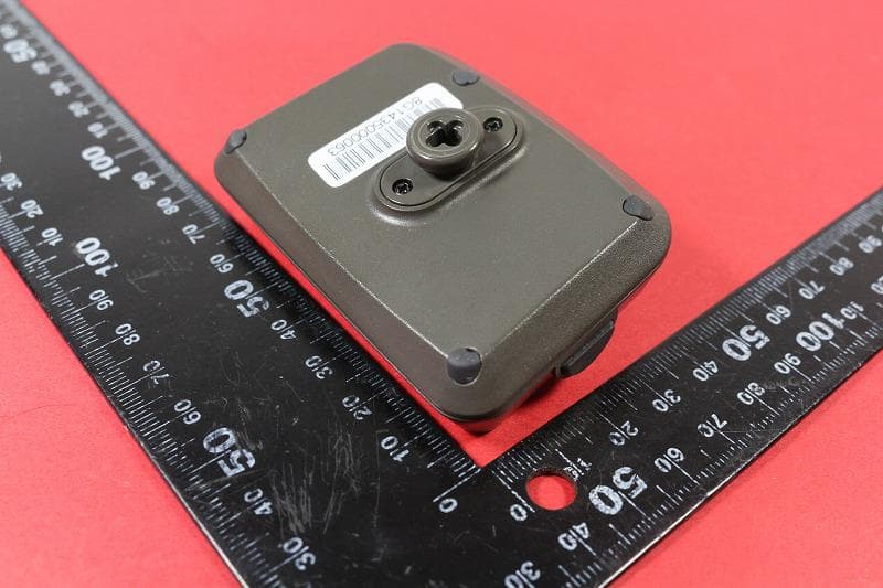
X8F-GT2
Oct 24, 2015Game Tracker
Equipment Class
DXX - Part 15 Low Power Communication Device Transmitter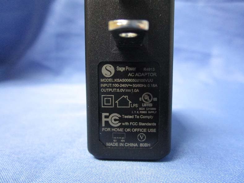
X8F-SCTOUCH
Apr 29, 2015SkyCaddie
Equipment Class
DSS - Part 15 Spread Spectrum Transmitter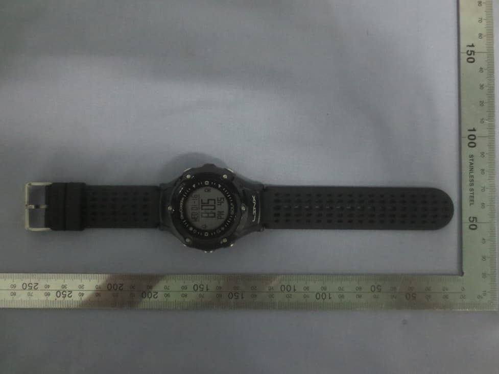
X8FM13-535LINX
Jun 02, 2014Golf GPS watch
Equipment Class
DTS - Digital Transmission System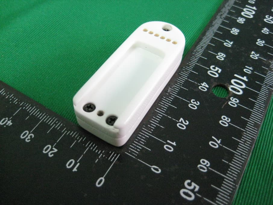
X8F-SKYPRO-BT
Apr 08, 2013Skypro Bluetooth Device
Equipment Class
DSS - Part 15 Spread Spectrum Transmitter