X9INCS01010910HANDHELD SECURITY DEVICE
New Centurion Solutions, Inc.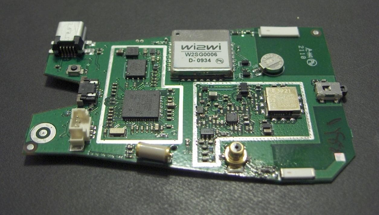
Click to zoom
Application Details
- Equipment Class
- DSS - Part 15 Spread Spectrum Transmitter
- Date of Grant
- Apr 12, 2011
- Application Purpose
- Original Equipment
- Date of Application
- Apr 12, 2011
- Equipment Note
- HANDHELD SECURITY DEVICE
- Frequency Range
- 902.50000000 - 927.50000000
- Country
- United States
Documents & Files
Document Text
Text extracted from the exhibit documents filed with the FCC. Open a document above to read the original.
Users Manual
THE INFORMATION CONTAINED HEREIN IS PROPRIETARY TO NEW CENTURION SOLUTIONS, INC. AND SHALL NOT BE REPRODUCED OR DISCLOSED IN WHOLE OR IN PART FOR ANY DESIGN OR MANUFACTURE EXCEPT WHEN SUCH USER POSSESSES DIRECT, WRITTEN AUTHORIZATION FROM NEW CENTURION SOLUTIONS, INC. PAS User Manual Original Document: March 1, 2011 Revision A: March 16, 2011 Revision B: April 25, 2011 Revision C: August 4, 2011 For Customer Service please email: [email protected] PAS User Manual THE INFORMATION CONTAINED HEREIN IS PROPRIETARY TO NEW CENTURION SOLUTIONS, INC. AND SHALL NOT BE REPRODUCED OR DISCLOSED IN WHOLE OR IN PART FOR ANY DESIGN OR MANUFACTURE EXCEPT WHEN SUCH USER POSSESSES DIRECT, WRITTEN AUTHORIZATION FROM NEW CENTURION SOLUTIONS, INC. ii Revision Page Rev Description Section A FCC Notification 15 B Update Pictures ALL C Update Pictures and Modify Descriptions ALL PAS User Manual THE INFORMATION CONTAINED HEREIN IS PROPRIETARY TO NEW CENTURION SOLUTIONS, INC. AND SHALL NOT BE REPRODUCED OR DISCLOSED IN WHOLE OR IN PART FOR ANY DESIGN OR MANUFACTURE EXCEPT WHEN SUCH USER POSSESSES DIRECT, WRITTEN AUTHORIZATION FROM NEW CENTURION SOLUTIONS, INC. iii Contents 1. Introduction PAS Basics .......................................................................................... 5 1.1 What is the PAS? ............................................................................................................ 5 1.2 How do I turn the PAS “on”? ........................................................................................ 5 1.3 How do I “wake up” my PAS? ....................................................................................... 5 2. Interfacing with the PAS ......................................................................................... 5 2.1 Performance Expectations ............................................................................................. 5 2.2 Emergency Button .......................................................................................................... 6 2.3 Scroll Buttons .................................................................................................................. 6 3. Sending an Emergency Request for Assistance ...................................................... 7 4. Receiving a Message ................................................................................................ 7 4.1 Flash Screen ..................................................................................................................... 7 4.2 Vibrating .......................................................................................................................... 7 4.3 Beeping ............................................................................................................................. 7 5. What do I do if I Receive a Message ....................................................................... 7 5.1 Receiving Message .......................................................................................................... 7 5.2 Message Box .................................................................................................................... 7 5.3 Important Message ......................................................................................................... 8 6. Battery Life ............................................................................................................... 8 7. Display ...................................................................................................................... 8 7.1 Back Light ....................................................................................................................... 8 7.2 Display Layout.................................................................................................................. 8 8. Icons ......................................................................................................................... 9 8.1 Battery Status Indicator ................................................................................................. 9 9. User Menu ................................................................................................................ 9 9.1 Navigating Through the Menus ..................................................................................... 9 9.2 Device Information Screen ........................................................................................... 10 9.3 History ............................................................................................................................ 10 10. RFID Technology .................................................................................................. 10 11. GPS Technology ..................................................................................................... 10 PAS User Manual THE INFORMATION CONTAINED HEREIN IS PROPRIETARY TO NEW CENTURION SOLUTIONS, INC. AND SHALL NOT BE REPRODUCED OR DISCLOSED IN WHOLE OR IN PART FOR ANY DESIGN OR MANUFACTURE EXCEPT WHEN SUCH USER POSSESSES DIRECT, WRITTEN AUTHORIZATION FROM NEW CENTURION SOLUTIONS, INC. iv 12. Taking Care of Your PAS ...................................................................................... 11 12.1 Charging the battery ................................................................................................. 11 12.2 Label Location ........................................................................................................... 11 12.3 Water Resistance ....................................................................................................... 11 13. General Troubleshooting ....................................................................................... 11 14. Important Safety and Handling Information ....................................................... 12 14.1 Carrying and Handling PAS Device .................................................…
Text truncated - open the document above for the full version.
ID Label/Location Info
FCC ID: X9INCS01010910
ID Label/Location Info
FCC Label Location
Internal Photos
PAS Internal Photos Back Side of Board GPS Module – pre-FCC Certified On-board GPS chip antenna On-board 915 mHz chip antenna Radio Module – pre-FCC certified RF Circuitry – Shielded Digital Circuitry – Shielded Front side Display Back side Display Front Side of Board
Parts List/Tune Up Info
PAS Device ItemQTYDesignatorDescription 1Manufacturer Manufacturer Part Number Source/Rep/Dist 1 1 ANT11.57 GHz AntennaJohanson Technology Inc.1575AT47A40E Arrow 2 1 ANT2915 MHz AntennaJohanson Technology Inc.0915AT43A0026 Arrow 3 1 BT1BATTERY LITHIUM 3.1V RECHARGESeiko InstrumentsMS518SE-FL35E Seiko 4 1 C1CAP 2200PF 25V CERAMIC 0402 SMDPanasonic - ECGECJ-0EB1E222K Arrow 5 2 C2, C3CAP CER 2.2PF 50V S 0402 UHI QJohanson Technology Inc500R07S2R2BV4T Arrow 6 5 C4, C5, C46, C47, C221CAP 22PF 50V CERAMIC 0402 SMDPanasonic - ECGECJ-0EC1H220J Arrow 7 3 C7, C201, C214CAP CER 47PF 50V NP0 0402Johanson Dielectrics Inc500R07N470JV4T Arrow 8 15 C10, C12, C15, C17, C19, C22, C24, C26, C28, C30, C32, C40, C42, C115, C222 CAP .1UF 10V CERAMIC X5R 0402Panasonic - ECGECJ-0EB1A104K Arrow 9 3 C11, C21, C34CAP CERAMIC 10UF 10V 0603 X5RPanasonic - ECGECJ-1VB1A106M Arrow 10 5 C13, C35, C37, C39, C41CAP CER 4.7UF 10V Y5V 0603Murata Electronics North AmericaGRM188F51A475ZE20D Arrow 11 12 C14, C16, C18, C20, C23, C25, C27, C29, C31, C33, C36, C38 CAP CERAMIC 1UF 10V X5R 0402Panasonic - ECGECJ-0EB1A105M Arrow 12 1 C44CAP .01UF 25V CERAMIC X7R 0402Panasonic - ECGECJ-0EB1E103K Arrow 13 6 C45, C100, C101, C202, C203, C208 CAP 100PF 50V CERAMIC 0402 SMDPanasonic - ECGECJ-0EC1H101J Arrow 14 2 C48, C217CAP CER 5.6PF 50V S 0402 UHI QJohanson Technology Inc500R07S5R6CV4T Arrow 15 1 C114CAP CER 5.1PF 50V C0G 0402Murata Electronics North AmericaGRM1555C1H5R1DZ01D Arrow 16 5 C116, C204, C212, C213, C215CAP CER 33PF 25V S 0402 UHI QJohanson Technology Inc250R07S330GV4T Arrow 17 2 C205, C207CAP CER 3.6PF 50V S 0402 UHI QJohanson Technology Inc500R07S3R6BV4T Arrow 18 1 C206CAP CER 6.2PF 50V S 0402 UHI QJohanson Technology Inc500R07S6R2CV4T Arrow 19 2 C209, C226CAP 10000PF 16V CERAMIC 0402 SMDPanasonic - ECGECJ-0EB1C103K Arrow 20 1 C210CAP 1000PF 25V CERAMIC 0402 SMDPanasonic - ECGECJ-0EB1E102K Arrow 21 4 C211, C223, C224, C225CAP 27PF 50V CERAMIC 0402 SMDPanasonic - ECGECJ-0EC1H270J Arrow 22 1 C216CAP CER 10PF 50V S 0402 UHI QJohanson Technology Inc500R07S100JV4T Arrow 23 1 C218CAP CER 3.3PF 50V S 0402 UHI QJohanson Technology Inc500R07S3R3BV4T Arrow 24 1 C219CAP 1.5PF 50V CERAMIC 0402 SMDPanasonic - ECGECJ-0EC1H1R5C Arrow 25 1 C220CAP CER 10UF 16V X5R 20% 0805AVX Corporation0805YD106MAT2A Arrow 26 1 C227CAP CER 15PF 50V S 0402 UHI QJohanson Technology Inc500R07S150JV4T Arrow 27 2 D2, D6DIODE SW 250MA 80V 150W SOT-523Micro Commercial CoMMBD4448HT-TP Arrow 28 2 D4, D5DIODE SCHOTTKY 500MA 20V 0603Comchip TechnologyCDBU0520 Arrow 29 1 DS1LCD DISP TFT 2.0" 176 x 220 B/LCrystalfontzCFAF176220M-T Arrow 30 1 FB200FERRITE CHIP 30 OHM 2200MA 0402Murata Electronics North AmericaBLM15PD300SN1D Arrow 31 2 FLT200, FLT201FILTER SAW ISM 915MHZ RFID SMDMurata Electronics North AmericaSAFEB915MAL0F00R12 Arrow 32 1 J2CONN FPC/FFC 5POS .5MM R/A SMDFCISFV5R-2STE1LF Arrow 33 1 J3CONN RCPT MINI USB2.0 5POS SMDHirose Electric Co LtdUX60RA-MB-5ST Arrow 34 1 L2CER INDUCTOR 4.7NH 0402Johanson Technology IncL-07C4N7SV6T Arrow ItemQTYDesignatorDescription 1Manufacturer Manufacturer Part Number Source/Rep/Dist 35 3 L201, L202, L206INDUCTOR 10NH 500MA 0402Murata Electronics North AmericaLQW15AN10NJ00D Arrow 36 1 L203INDUCTOR 11NH .64A WW 0402Wurth Electronics Inc744765111A Arrow 37 1 L204CER INDUCTOR 27NH 0402Johanson Technology IncL-07C27NJV6T Arrow 38 1 L205CER INDUCTOR 2.2NH 0402Johanson Technology IncL-07C2N2SV6T Arrow 39 1 L207INDUCTOR MULTILAYER 1.6NH 0402TDK CorporationMLG1005S1N6S Arrow 40 1 L208CER INDUCTOR 15NH 0402Johanson Technology IncL-07C15NJV6T Arrow 41 1 LS1BUZZER MAGNETIC 3V 5MM SMDPUI AudioSMT-0540-S-R PUI Audio 42 1 MD1MODULE GPSWi2WiW2SG0006-006F-11WW Roy Zappia 43 1 MD100MOD 802.15.4/ZIGB 900MHZ RF OUTPanasonicENW-59611N3A Arrow 44 1 MP1RF Shield, 27.89 x 17.96 x 2.5 mm (48 MHz)GenesisGTI09-60347 Rev6 Ken Erickson 45 1 MP2RF Shield, 18.97 x 23.47 x 2.5 mm (900 MHz)GenesisGTI09-60348 Rev5 Ken Erickson 46 1 P2CONN HEADER 3POS 1.25MM VERT SMDMolex Connector Corporation53398-0371 Arrow 47 1 P200CONN RECEPT COAX SWITCHING SMTHirose Electric Co LtdMS-147(06) Arrow 48 3 Q1, Q2, Q3MOSFET N-CH 20V 200MA 3-DFNDiodes IncDMN2005LP4K-7 Arrow 49 1 Q4MOSFET P-CH 20V 1.5A 3-DFNDiodes IncDMP2104LP-7 Arrow 50 1 R2RES 174K OHM 1/10W 1% 0402 SMDPanasonic - ECGERJ-2RKF1743X Arrow 51 5 R3, R100, R101, R200, R202RES 1.0K OHM 1/16W 5% 0402 SMDRohm SemiconductorMCR01MZPJ102 Arrow 52 3 R4, R5, R6RESISTOR 6.2 OHM 1/10W 5% 0402Panasonic - ECGERJ-2GEJ6R2X Arrow 53 3 R7, R201, R203RES 0.0 OHM 1/16W 5% 0402 SMDRohm SemiconductorMCR01MZPJ000 Arrow 54 1 R8RES 20K OHM 1/10W 5% 0402 SMDPanasonic - ECGERJ-2GEJ203X Arrow 55 2 R9, R19RES 560 OHM 1/10W 5% 0402 SMDPanasonic - ECGERJ-2GEJ561X Arrow 56 1 R10RES 2.10K OHM 1/10W 1% 0402 SMDPanasonic - ECGERJ-2RKF2101X Arrow 57 1 R11RES 71.5K OHM 1/10W 1% 0402 SMDPanasonic - ECGERJ-2RKF7152X Arrow 58 6 R12, R25, R26, R27, R28, R30RES 10K OHM 1/10W 5% 0402 SMDPanasonic - ECGERJ-2GEJ103X Arrow 59 1 R13RESISTOR 1.0 OHM 1/10W 5% 0603Panasonic - ECGERJ-3GEYJ1R0V Arrow 60 2 R14, R15RES 27.0 OHM 1/10W 1% 0402 SMDPanasonic - ECGERJ-2RKF27R0X Arrow 61 1 R16RES 100K OHM 1/10W 5% 0402 SMDPanasonic - ECGERJ-2GEJ104X Arrow 62 1 R17RES 1.00M OHM 1/10W 1% 0402 SMDPanasonic - ECGERJ-2RKF1004X Arrow 63 1 R18RES 3.74M OHM 1/16W 1% 0402 SMDVishay/DaleCRCW04023M74FKED Arrow 64 3 R20, R21, R22RES 300 OHM 1/10W 5% 0402 SMDPanasonic - ECGERJ-2GEJ301X Arrow 65 1 R24RES 249K OHM 1/10W 1% 0402 SMDPanasonic - ECGERJ-2RKF2493X Arrow 66 1 R31RES 200 OHM 1/10W 5% 0402 SMDPanasonic - ECGERJ-2GEJ201X Arrow 67 1 R33RES ZERO OHM 1/10W 5% 0603 SMDPanasonic - ECGERJ-3GEY0R00V Arrow 68 2 R34, R35RES 5.1K OHM 1/10W 5% 0402 SMDPanasonic - ECGERJ-2GEJ512X Arrow 69 2 R204, R205RES 120 OHM 1/10W 5% 0402 SMDPanasonic - ECGERJ-2GEJ121X Arrow 70 1 SEN1Omnidirectional Tilt and Vibration SensorSignalQuest Precision MicrosensorsSQ-SEN-200 SignalQuest 71 1 SW1SWITCH TACT SPST W/O GND SMDOmron Electronics Inc-ECB DivB3U-1000P Arrow 72 1 SW2SWITCH LIGHT TOUCH 160GF SMDPanasonic …
Text truncated - open the document above for the full version.
RF Exposure Info
THE INFORMATION CONTAINED HEREIN IS PROPRIETARY TO ELLIOTT TECH, LLC AND SHALL NOT BE REPRODUCED OR DISCLOSED IN WHOLE OR IN PART FOR ANY DESIGN OR MANUFACTURE EXCEPT WHEN SUCH USER POSSESSES DIRECT, WRITTEN AUTHORIZATION FROM ELLIOTT TECH, LLC. Elliott Tech, LLC RF Exposure Exhibit Project Number: 776 Reference: 776-91-RF Exposure Exhibit.docx Original Release: March 7, 2011 *Note: Documentation illustrating the duty cycles and coincidence of operation will be provided with FCC formal compliance testing results. Prepared for: Prepared by: Joey Han – Project Engineer Elliott Tech, LLC 346 Raleigh Street Holly Springs, North Carolina Phone: (919) 342-6899 Fax: (480) 275-3311 [email protected] Elliott Tech, LLC 776-91-RF Exposure Exhibit.docx 1 RF EXPOSURE EXHIBIT The Specific Absorption Rate (SAR) is a measure of the heating value of radiated Radio Frequency (RF) energy on human tissue, and thus effectively evaluates the biological safety of low-power transmitters in close proximity to the human body. The FCC exposure evaluation expresses these RF exposure limits in terms of SAR. The purpose of this exhibit is to describe why SAR testing is not necessary for the NCS Personal Alert Sentry (PAS) device. There exist three FCC classifications for wireless devices: fixed, mobile, and portable. Fixed devices are permanently located with an antenna affixed to a structure and are not required for SAR testing. Mobile devices are used 20 cm or more from the body and portable devices are used within 20 cm of the body. Although the PAS will likely be carried within 20 cm of the body in normal operation, is only able to transmit by active button press (when held in the hand), and therefore should be considered a mobile device as opposed to a portable device. The PAS device operates in the ISM band and transmits using GFSK modulation with a unity gain antenna, frequency hopping from 902.5 MHz to 927.5 MHz with less than a 400ms dwell time as regulated by the FCC (15.247). The output power is 900mW with a maximum transmit duty cycle of 38% (transmitter is only active 38ms at most in any 100ms window). Applying this duty cycle reduces the output transmit power to 342mW. Although this transmit power is clearly above the 65.57mW output power threshold required for SAR testing, we do not believe that SAR testing is necessary for the PAS device. First and foremost, this is a personal safety device; under normal operation it only transmits in the event of an emergency in which an alert button press is required. Furthermore, there is no audible feedback from the device and therefore offers no incentive for use around the head. Realistically, the device will only transmit once/twice in the lifetime of the product if even at all. In the event of an alert transmission, the PAS device must be secured in the palm of the hand and initiated with a finger triggering the button on the top of the device. Even when sending an alert, the transmitter will only remain on for a very brief period of time. In the worst case, the PAS will transmit for 38ms (in a 272ms window) three times in order to completely send the alert packet. In addition, KDB 447498 D01, Item 4, Section C, Part iii (1) reads: “Hand SAR is required for hand-held and hand-operated devices with output power > mW that are Elliott Tech, LLC 776-91-RF Exposure Exhibit.docx 2 designed with the hand operating closer than 5 cm from the antenna during normal use.” Therefore, our output power (900mW) must be less than: . Our device clearly does not need Hand SAR testing as our transmit output power is less than the aforementioned threshold. Due to the minimal expected usage of the device as well as the brevity of the actual transmit in the unlikely event on an alert; we do not believe SAR testing is necessary for the NCS PAS device.
RF Exposure Info
Report Number: 11CA14739-PAS File Number: MC16660 Page 1 of 3 Model Number: PAS Client Name: Elliott Tech, LLC (FCC ID: X9INCS01010910) Page 1 of 3 1.1 Test Conditions and Results – MAXIMUM PERMISSIBLE EXPOSURE Test Description Maximum Permissible Exposure calculation is performed to ensure that this device meets RF exposure limits for its intended environment. This device is required to meet the General Population/Uncontrolled exposure limits. Basic Standard 47 CFR Part 1.1307 Industry Canada IC Safety Code 6 FCC Limits for Occupational/Controlled Exposure Frequency Range (MHZ) Electric Field Strength (E) (V/M) Magnetic Field Strength (H) (A/M) Power Density (S) (MW/CM 2 ) Averaging Time E 2 , H 2 . or S (MINUTES) 0.3 – 3.0 614 1.63 (100)* 6 3.0 - 30 1824/F 4.89/F (900/F 2 )* 6 30 - 300 61.4 0.163 1.0 6 300 – 1500 - - F/300 6 1500 – 100,000 - - 5.0 6 FCC Limits for General Population/Uncontrolled Exposure Frequency Range (MHz) Electric Field Strength (E) (V/m) Magnetic Field Strength (H) (A/m) Power Density (S) (mw/cm 2 ) Averaging Time E 2 , H 2 . or S (minutes) 0.3 - 1.34 614 1.63 (100)* 30 1.34 - 30 824/F 2.19/F (180/F 2 )* 30 30 - 300 27.5 0.073 0.2 30 300 – 1500 - - F/1500 30 1500 – 100,000 - - 1.0 30 Figure 1 MPE - EUT Configuration Settings Calculation is performed from conducted power and antenna gain measurements documented within this report. Report Number: 11CA14739-PAS File Number: MC16660 Page 2 of 3 Model Number: PAS Client Name: Elliott Tech, LLC (FCC ID: X9INCS01010910) Page 2 of 3 Background: Per the following guidance from OET Bulletin 65 Supplement C required minimum spacings are provided to the professional installer. Transmitter or Device Type 18 Output 19 Applicable Methods to Ensure Compliance 20 Transmitters using indoor antennas that operate at 20 cm or more from nearby persons >2.5 W at 915 MHz If the MPE distance is greater than that required for normal operation of the device, operating instructions, warning instructions and/or warning labels may be used to ensure compliance by indicating the minimal separation distance to comply with MPE limits. If the antennas are professionally installed to ensure compliance, warning instructions and warning labels are not necessary. = 2.5 W at 915 MHz or =< 4 W at 2450 MHz Transmitters operating at 2.5 W EIRP (1.5 W ERP) or less at 915 MHz, or at 4 W EIRP (2.4 W ERP) or less at 2450 MHz, generally are not expected to exceed MPE limits when nearby persons are 20 cm or more from most antennas. Therefore, special instructions and warnings are normally not necessary to ensure compliance. Figure 2 Duty Cycle Correction Factor Mode ON Duration (ms) Total Duration (ms) Duty Cycle Correction (dB) )log(20 100 )( ms msTX Comments Short Pulse 14 101.4 Long Transmission 38 171.6 Total 52 273.0 -14.4 dB 52ms / 273ms = 19.0% Report Number: 11CA14739-PAS File Number: MC16660 Page 3 of 3 Model Number: PAS Client Name: Elliott Tech, LLC (FCC ID: X9INCS01010910) Page 3 of 3 Figure 3 MPE - Calculation MPE Calculation with highest EIRP: The highest conducted power was observed to be 617 mW and this measurement is used for the calculation. Limit is calculated at low channel (902.5 MHz) as exposure limit increases slightly with frequency in the operating band. Duty cycle is 14.4%. S = EIRP / (4 * Pi * R 2 ), Power Density = EIRP / (4 * Pi * R 2 ), where EIRP = Output Power * Antenna Gain Uncontrolled/General Exposure 0.617 Watt, 0.00 dBi antenna (Unity Gain), 20 cm spacing Operating Frequency 902.5 MHz Output Power (Peak) 0.617 Watts Antenna Gain -1.0 dB or (linear) 0.794(unitless) Separation Distance 0.2 m -or- 7.874inches Peak Power Density 0.975 W/m 2 - or - 0.0975mW/cm 2 Exposure % (over 6 min timespan for uncontrolled) 100% Transmit Duty Cycle (Peak-to-Average Ratio) 14.4% Average Power Density 0.1404 W/m 2 - or - 0.01404 mW/cm 2 Limit for Uncontrolled Exposure at Operating Frequency 6.01667 W/m 2 - or - 0.60167 mW/cm 2 The product was found to comply with this requirement.
Test Report
Underwriters Laboratories Inc. A not-for-profit organization dedicated 12 Laboratory Dr. to public safety and committed to Research Triangle Park, NC 27709 quality service for over 100 years Tel: (919) 549-1400 Underwriters Laboratories Inc. 12 Laboratory Dr. Research Triangle Park, NC 27709 www.ul.com/emc (919) 549-1400 Lab Number: R11CA14739-PAS Project Number: 11CA14739 File Number: MC16660 Date: March 28, 2011 Model: PAS (FCC ID: X9INCS01010910) Electromagnetic Compatibility Test Report For Elliott Tech LLC Raleigh, NC Copyright 2010 Underwriters Laboratories Inc. Underwriters Laboratories Inc. authorizes the above-named company to reproduce this Report provided it is reproduced in its entirety. Report Number: 11CA14739-PAS File Number: MC16660 Page 2 of 49 Model Number: PAS Client Name: Elliott Tech, LLC (FCC ID: X9INCS01010910) Page 2 of 49 Test Report Details Tests Performed By: Underwriters Laboratories Inc. 12 Laboratory Dr. Research Triangle Park, NC 27709 Tests Performed For: Elliott Tech, LLC 346 Raleigh Street Holly Springs, NC 27540 Applicant Contact: Krista L. Larrison Title: Project Administrator Phone: +1 (919) 342-6899 Fax: +1 (888) 631-1795 E-mail: [email protected] Test Report Date: March 28, 2010 Product Type: Unlicensed Transmitter Product standards FCC Part 15, Subpart C, 15.247 Model Number: PAS Sample Serial Number: Unserialized, pre-production sample EUT Category: Low Power Transmitter 902-928 MHz Testing Start Date: March 7, 2011 Date Testing Complete: March 11, 2011 (Follow-up Measurement on March 31, 2011) Overall Results: Compliant Underwriters Laboratories Inc. reports apply only to the specific samples tested under stated test conditions. All samples tested were in good operating condition throughout the entire test program. It is the manufacturer's responsibility to assure that additional production units of this model are manufactured with identical electrical and mechanical components. Underwriters Laboratories Inc. shall have no liability for any deductions, inferences or generalizations drawn by the client or others from Underwriters Laboratories Inc. issued reports. This report shall not be used to claim, constitute or imply product certification, approval, or endorsement by NVLAP, NIST, A2LA, or any agency of the US government. This report may contain test results that are not covered by the NVLAP or A2LA accreditation. The scope of accreditation is limited to the specific tests that are listed on the NVLAP and/or A2LA websites referenced at the end of this report. Report Number: 11CA14739-PAS File Number: MC16660 Page 3 of 49 Model Number: PAS Client Name: Elliott Tech, LLC (FCC ID: X9INCS01010910) Page 3 of 49 Report Directory 1.0 G E N E R A L - Product Description ................................................................................................................. 4 1.1 Equipment Description .................................................................................................................................. 4 1.2 Device Configuration During Test ................................................................................................................. 5 1.2.1 Equipment Used During Test: ................................................................................................................... 5 1.2.2 Input/Output Ports: .................................................................................................................................... 5 1.2.3 EUT Internal Operating Frequencies: ....................................................................................................... 6 1.2.4 Power Interface: ........................................................................................................................................ 6 1.3 Block Diagram: .............................................................................................................................................. 6 1.4 EUT Configurations ....................................................................................................................................... 6 1.5 EUT Operation Modes .................................................................................................................................. 6 1.6 Test Setup Photos ......................................................................................................................................... 6 2.0 Summary ........................................................................................................................................................... 7 2.1 Deviations from standard test methods ........................................................................................................ 7 2.2 Device Modifications Necessary for Compliance .......................................................................................... 7 2.3 Reference Standards .................................................................................................................................... 8 2.4 Results Summary .......................................................................................................................................... 8 3.0 Calibration of Equipment Used for Measurement ............................................................................................. 9 4.0 EMISSIONS TEST RESULTS ........................................................................................................................... 9 4.1 Test Conditions and Results – RADIATED SPURIOUS EMISSIONS ........................................................ 10 4.2 Test Conditions and Results – CONDUCTED SPURIOUS EMISSIONS ................................................... 19 4.3 Test Conditions and Results – BAND EDGE .............................................................................................. 24 4.4 Test Conditions and Results – FREQUENCY HOPPING .......................…
Text truncated - open the document above for the full version.
Test Setup Photos
HUB Indoor Repeater Outdoor Repeater PAS HUB Active GPS Antenna Switcher @ 550KHz Power Switch USB Connection Antenna Indoor Repeater Active GPS Antenna GPS Module – pre-FCC certified RF Module – pre-FCC certified RF Interconnect Digital Circuitry – can be shielded Radio Circuitry - Shielded Outdoor Repeater Antenna Connector Type - N GPS Module – pre-FCC certified RF Module – pre-FCC certified Digital Circuitry – can be shielded Radio Circuitry - Shielded PAS Digital Circuitry – Shielded RF Circuitry – Shielded GPS Module – pre-FCC Certified On-board GPS chip antenna On-board 915 mHz chip antenna Radio Module – pre-FCC certified SN: FG9023 SN: FG9020 Description of pictures:
Test Setup Photos
Test Setup Photos – PAS Radiated Spurious Emissions – Flat (from rear) Radiated Spurious Emissions – Flat (from front) Note: Polystyrene foam and duct tape is used for positioning only. Radiated Spurious Emissions – Side (from rear) Radiated Spurious Emissions – Side (from front) Radiated Spurious Emissions – Upright (from front) Radiated Spurious Emissions – Upright (from front) Conducted Power/Conducted Spurious Emissions Setup for Conducted Spurious Emissions is identical for PAS, Hub, Indoor Repeater, and Outdoor Repeater
Contact Information
Applicant
Greg Williams(Owner)
Test Firm
UL LLCRick Titus
Technical Specifications
| # | Rule Parts | Frequency Range | Power Output |
|---|---|---|---|
| 1 | 15C | 902.5 MHz - 927.5 MHz | 617.00 mW |
Other Applications from New Centurion Solutions, Inc.
X9INCS04010910
Apr 18, 2011HANDHELD SECURITY DEVICE
Equipment Class
DSS - Part 15 Spread Spectrum Transmitter
X9INCS03010910
Apr 18, 2011HANDHELD SECURITY DEVICE
Equipment Class
DSS - Part 15 Spread Spectrum Transmitter
X9INCS02010910
Apr 18, 2011HANDHELD SECURITY DEVICE
Equipment Class
DSS - Part 15 Spread Spectrum Transmitter