X9INCS02010910HANDHELD SECURITY DEVICE
New Centurion Solutions, Inc.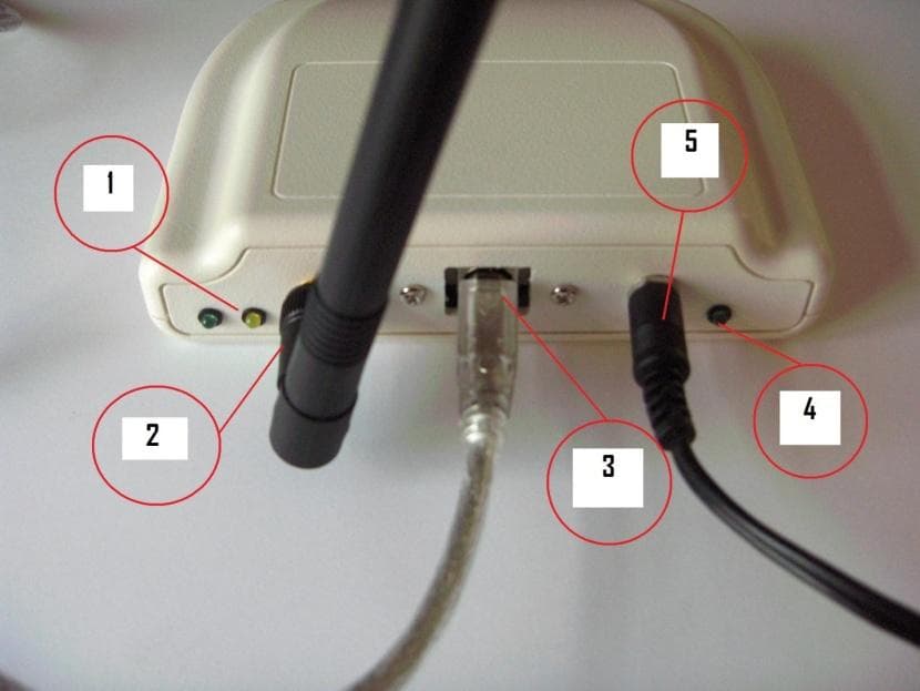
Click to zoom
Application Details
- Equipment Class
- DSS - Part 15 Spread Spectrum Transmitter
- Date of Grant
- Apr 18, 2011
- Application Purpose
- Original Equipment
- Date of Application
- Apr 18, 2011
- Equipment Note
- HANDHELD SECURITY DEVICE
- Frequency Range
- 902.50000000 - 927.50000000
- Country
- United States
Documents & Files
Document Text
Text extracted from the exhibit documents filed with the FCC. Open a document above to read the original.
Users Manual
THE INFORMATION CONTAINED HEREIN IS PROPRIETARY TO NEW CENTURION SOLUTIONS, INC. AND SHALL NOT BE REPRODUCED OR DISCLOSED IN WHOLE OR IN PART FOR ANY DESIGN OR MANUFACTURE EXCEPT WHEN SUCH USER POSSESSES DIRECT, WRITTEN AUTHORIZATION FROM NEW CENTURION SOLUTIONS, INC. Elliott Tech, LLC HUB Assembly Manual HUB New Centurion Solutions Project Number: 776 Reference: 776-91-02-REV-.docx Original Document: March 1, 2011 Revision A: March 16, 2011 Prepared for: Prepared by: New Centurion Solutions, Inc. Greg Williams 3011 Spring Garden St. Suite E Greensboro, NC 27403 (336) 617-5410 [email protected] Elliott Tech, LLC 346 Raleigh Street Holly Springs, NC 27540 (919) 342-6899 (888) 631-1795 Fax [email protected] HUB Assembly Manual 776-91-02-REV-A.docx THE INFORMATION CONTAINED HEREIN IS PROPRIETARY TO NEW CENTURION SOLUTIONS, INC. AND SHALL NOT BE REPRODUCED OR DISCLOSED IN WHOLE OR IN PART FOR ANY DESIGN OR MANUFACTURE EXCEPT WHEN SUCH USER POSSESSES DIRECT, WRITTEN AUTHORIZATION FROM NEW CENTURION SOLUTIONS, INC. ii Revision Page Rev Description Section A FCC Notification 3 HUB Assembly Manual 776-91-02-REV-A.docx THE INFORMATION CONTAINED HEREIN IS PROPRIETARY TO NEW CENTURION SOLUTIONS, INC. AND SHALL NOT BE REPRODUCED OR DISCLOSED IN WHOLE OR IN PART FOR ANY DESIGN OR MANUFACTURE EXCEPT WHEN SUCH USER POSSESSES DIRECT, WRITTEN AUTHORIZATION FROM NEW CENTURION SOLUTIONS, INC. iii Contents 1. Equipment List ......................................................................................................... 4 2. Assembly Instructions .............................................................................................. 5 3. FCC Notification ...................................................................................................... 8 HUB Assembly Manual 776-91-02-REV-A.docx THE INFORMATION CONTAINED HEREIN IS PROPRIETARY TO NEW CENTURION SOLUTIONS, INC. AND SHALL NOT BE REPRODUCED OR DISCLOSED IN WHOLE OR IN PART FOR ANY DESIGN OR MANUFACTURE EXCEPT WHEN SUCH USER POSSESSES DIRECT, WRITTEN AUTHORIZATION FROM NEW CENTURION SOLUTIONS, INC. 4 1. EQUIPMENT LIST A. Barrel Jack Power Connector (1) B. Hub Enclosure - Top (1) C. 2 Position Connector Header (4) D. Hub Enclosure - Bottom (1) E. Connector Crimp Terminals (8) F. Hub Enclosure - Front (1) G. Miniature Coaxial Cable Plug-SMA Jack (1) H. Hub Enclosure - Screws (4) I. Two Way 1/2 Wave Dipole Antenna (1) J. Hub PCB (1) K. USB 5 Pin Panel Mount Cable (1) L. Dark Green LED Snap In Panel Indicator (2) M. Hex .250”L Phillips Head Stand-off (2) N. Light Green/Yellow LED Snap In Panel Indicator (1) O. 1/4” Steel Pan Phillips Screw (4) P. AC/DC 5V Power Adapter (1) Q. Loctite Epoxy Quick Set R. UL Power Cord (1) HUB Assembly Manual 776-91-02-REV-A.docx THE INFORMATION CONTAINED HEREIN IS PROPRIETARY TO NEW CENTURION SOLUTIONS, INC. AND SHALL NOT BE REPRODUCED OR DISCLOSED IN WHOLE OR IN PART FOR ANY DESIGN OR MANUFACTURE EXCEPT WHEN SUCH USER POSSESSES DIRECT, WRITTEN AUTHORIZATION FROM NEW CENTURION SOLUTIONS, INC. 5 2. ASSEMBLY INSTRUCTIONS To begin, check the parts available against the equipment list, identifying any missing parts. If all parts are accounted for, proceed to the instructions below to begin assembling the HUB. Step 1: Identify the two stand-offs (M) and four Phillips screws (H). Place the two standoffs beneath the PCB (J), lining up the holes on the board with the holes in the stand-offs. Insert a screw into both corners, effectively attaching the stand-offs to the bottom of the board. Flip the PCB over and line up the other two corners to the existing screw holes on the bottom enclosure. Follow the instructions on the Epoxy (Q) to mix the resin and hardener. Place the mixed adhesive solution along the base of the stand-offs and press against the bottom enclosure making a firm seal. When the adhesive is dry, unscrew the PCB from the two stand-offs, which should now be firmly attached to the bottom enclosure. After verifying, line up the four corners so that each has a screw hole and insert the four Phillips screws attaching the PCB to the bottom enclosure. Note that the stand-offs can be offset (do not need to make a square in respect to the existing screw holes on the bottom enclosure) as there are two holes in each corner of the board. Step 2: Identify the three panel indicators, there should be two dark green LEDs (L) and one light green/yellow LED (N). Although not necessary, the respective panel indicator wires (red and black) can be cut to around half the length and re-stripped in order to prevent against excessive folding of the wires inside the enclosure as the wires are much longer than required. Take the first indicator (order does not matter) and place a crimp terminal (L) on the end of one of the wires. Using a crimp tool, crimp the terminal into place on the end of the wire. Repeat for all six wires attached to the three panel indicators. Step 3: Take the front enclosure (F) and identify the rough side as opposed to the smooth side. Feed the three panel indicators into the rough side, wires first. The front enclosure has three small identical holes seperated into a single hole on one side, and two holes on the other. Looking at the rough side of the enclosure, the first dark green panel indicator should be fed into the rightmost isolated hole. The light green/yellow panel indicator should be fed into the closest of the two holes to the middle. The other dark green indicator should be fed into the farther of the two holes from the middle. The panel indicators will snap into place when they are pushed all the way into the holes. Next, feed the crimp terminals into the 2 position connector header (C). The terminals should be inserted into the end with the larger openings. Be sure to take careful note of the positions of the wires. As indicated in the figure, with the connector ears on the right, the red crimp wire should be inserted into the top position while the black c…
Text truncated - open the document above for the full version.
Users Manual
THE INFORMATION CONTAINED HEREIN IS PROPRIETARY TO NEW CENTURION SOLUTIONS, INC. AND SHALL NOT BE REPRODUCED OR DISCLOSED IN WHOLE OR IN PART FOR ANY DESIGN OR MANUFACTURE EXCEPT WHEN SUCH USER POSSESSES DIRECT, WRITTEN AUTHORIZATION FROM NEW CENTURION SOLUTIONS, INC. Elliott Tech, LLC HUB Installation Manual HUB New Centurion Solutions Project Number: 776 Reference: 776-91-05-REV-HUB_INSTALLATION_MANUAL.docx Original Document: March 1, 2011 Revision A: March 16, 2011 Prepared for: Prepared by: New Centurion Solutions, Inc. Greg Williams 3011 Spring Garden St. Suite E Greensboro, NC 27403 (336) 617-5410 [email protected] Elliott Tech, LLC 346 Raleigh Street Holly Springs, NC 27540 (919) 342-6899 (888) 631-1795 Fax [email protected] HUB Installation Manual 776-91-05-REV-A_HUB_INSTALLATION_MANUAL.docx THE INFORMATION CONTAINED HEREIN IS PROPRIETARY TO NEW CENTURION SOLUTIONS, INC. AND SHALL NOT BE REPRODUCED OR DISCLOSED IN WHOLE OR IN PART FOR ANY DESIGN OR MANUFACTURE EXCEPT WHEN SUCH USER POSSESSES DIRECT, WRITTEN AUTHORIZATION FROM NEW CENTURION SOLUTIONS, INC. ii Revision Page Rev Description Section A FCC Notification 3 HUB Installation Manual 776-91-05-REV-A_HUB_INSTALLATION_MANUAL.docx THE INFORMATION CONTAINED HEREIN IS PROPRIETARY TO NEW CENTURION SOLUTIONS, INC. AND SHALL NOT BE REPRODUCED OR DISCLOSED IN WHOLE OR IN PART FOR ANY DESIGN OR MANUFACTURE EXCEPT WHEN SUCH USER POSSESSES DIRECT, WRITTEN AUTHORIZATION FROM NEW CENTURION SOLUTIONS, INC. iii Contents 1. Equipment List ......................................................................................................... 4 2. Installation Instructions .......................................................................................... 5 3. FCC Notification ...................................................................................................... 6 HUB Installation Manual 776-91-05-REV-A_HUB_INSTALLATION_MANUAL.docx THE INFORMATION CONTAINED HEREIN IS PROPRIETARY TO NEW CENTURION SOLUTIONS, INC. AND SHALL NOT BE REPRODUCED OR DISCLOSED IN WHOLE OR IN PART FOR ANY DESIGN OR MANUFACTURE EXCEPT WHEN SUCH USER POSSESSES DIRECT, WRITTEN AUTHORIZATION FROM NEW CENTURION SOLUTIONS, INC. 4 1. EQUIPMENT LIST A. USB Cable, Type A to Type B (1) B. Hub Assembly (1) C. Flexible ½ wave center-fed dipole antenna with articulated knuckle (1) D. HUB Power Supply (1) E. Personal Computer (PC) (1) F. U.L. approved power cord, 6 ft. length (1) HUB Installation Manual 776-91-05-REV-A_HUB_INSTALLATION_MANUAL.docx THE INFORMATION CONTAINED HEREIN IS PROPRIETARY TO NEW CENTURION SOLUTIONS, INC. AND SHALL NOT BE REPRODUCED OR DISCLOSED IN WHOLE OR IN PART FOR ANY DESIGN OR MANUFACTURE EXCEPT WHEN SUCH USER POSSESSES DIRECT, WRITTEN AUTHORIZATION FROM NEW CENTURION SOLUTIONS, INC. 5 2. INSTALLATION INSTRUCTIONS To begin, check the parts available against the equipment list, identifying any missing parts. If all parts are accounted for, proceed to the instructions below to begin installing the HUB. Step 1: Identify the Flexible ½ wave center-fed dipole antenna with articulated knuckle (C). Screw the antenna into the gold coaxial antenna connector on the front panel of the HUB assembly (B). Ensure that the antenna is screwed onto the connector snugly, but take care not to over-tighten the antenna as it will damage the connector or the HUB assembly front panel. Step 2: Identify the USB Cable, Type A to Type B (A). The type-A end of the cable is smaller and flatter than the type-B end of the cable and will mate with a standard USB port on a PC. Plug this end into one of the USB ports on the Personal Computer (PC) (E). Plug the other end (Type-B) into the mating USB connector on the front panel of the HUB assembly (B). Type-A Type-B HUB Installation Manual 776-91-05-REV-A_HUB_INSTALLATION_MANUAL.docx THE INFORMATION CONTAINED HEREIN IS PROPRIETARY TO NEW CENTURION SOLUTIONS, INC. AND SHALL NOT BE REPRODUCED OR DISCLOSED IN WHOLE OR IN PART FOR ANY DESIGN OR MANUFACTURE EXCEPT WHEN SUCH USER POSSESSES DIRECT, WRITTEN AUTHORIZATION FROM NEW CENTURION SOLUTIONS, INC. 6 Step 3: Identify the HUB Power Supply (D). Plug the barrel jack plug into the mating barrel jack on the front panel of the HUB assembly (B). Plug the U.L. approved power cord, 6 ft. length (F) into the HUB Power Supply (D). Only one end will mate with it properly. Plug the other end of the power cord into a standard 120 Volt wall outlet. The green light on the front panel of the HUB should illuminate. 1 – Green status indicator light / yellow status indicator light 2 – Flexible ½ wave center-fed dipole antenna with articulated knuckle 3 – USB cable type-B end, plugged into the HUB assembly 4 – Green power indicator light – this should illuminate whenever the HUB is correctly connected to a power source 5 – Barrel jack plug of HUB Power Supply (D), plugged into the barrel jack of the HUB assembly 3. FCC NOTIFICATION NOTE: THE MANUFACTURER IS NOT RESPONSIBLE FOR ANY RADIO OR TV INTERFERENCE CAUSED BY UNAUTHORIZED MODIFICATIONS TO THIS EQUIPMENT. SUCH MODIFICATIONS COULD VOID THE USER’S AUTHORITY TO OPERATE THE EQUIPMENT. THIS DEVICE COMPLIES WITH PART 15 OF THE FCC RULES. OPERATION IS SUBJECT TO THE FOLLOWING TWO CONDITIONS: (1) THIS DEVICE MAY NOT CAUSE HARMFUL INTERFERENCE, AND (2) THIS DEVICE MUST ACCEPT ANY INTERFERENCE RECEIVED, INCLUDING INTERFERENCE THAT MAY CAUSE UNDESIRED OPERATION.
Users Manual
THE INFORMATION CONTAINED HEREIN IS PROPRIETARY TO NEW CENTURION SOLUTIONS, INC. AND SHALL NOT BE REPRODUCED OR DISCLOSED IN WHOLE OR IN PART FOR ANY DESIGN OR MANUFACTURE EXCEPT WHEN SUCH USER POSSESSES DIRECT, WRITTEN AUTHORIZATION FROM NEW CENTURION SOLUTIONS, INC. Elliott Tech, LLC HUB Assembly Manual HUB New Centurion Solutions Project Number: 776 Reference: 776-91-02-REV-.docx Original Document: March 1, 2011 Prepared for: Prepared by: New Centurion Solutions, Inc. Greg Williams 3011 Spring Garden St. Suite E Greensboro, NC 27403 (336) 345-7411 [email protected] Elliott Tech, LLC 346 Raleigh Street Holly Springs, NC 27540 (919) 342-6899 (888) 631-1795 Fax [email protected] HUB Assembly Manual 776-91-02-REV-.docx THE INFORMATION CONTAINED HEREIN IS PROPRIETARY TO NEW CENTURION SOLUTIONS, INC. AND SHALL NOT BE REPRODUCED OR DISCLOSED IN WHOLE OR IN PART FOR ANY DESIGN OR MANUFACTURE EXCEPT WHEN SUCH USER POSSESSES DIRECT, WRITTEN AUTHORIZATION FROM NEW CENTURION SOLUTIONS, INC. ii Revision Page Rev Description Section HUB Assembly Manual 776-91-02-REV-.docx THE INFORMATION CONTAINED HEREIN IS PROPRIETARY TO NEW CENTURION SOLUTIONS, INC. AND SHALL NOT BE REPRODUCED OR DISCLOSED IN WHOLE OR IN PART FOR ANY DESIGN OR MANUFACTURE EXCEPT WHEN SUCH USER POSSESSES DIRECT, WRITTEN AUTHORIZATION FROM NEW CENTURION SOLUTIONS, INC. iii Contents 1. Equipment List ......................................................................................................... 4 2. Assembly Instructions .............................................................................................. 5 HUB Assembly Manual 776-91-02-REV-.docx THE INFORMATION CONTAINED HEREIN IS PROPRIETARY TO NEW CENTURION SOLUTIONS, INC. AND SHALL NOT BE REPRODUCED OR DISCLOSED IN WHOLE OR IN PART FOR ANY DESIGN OR MANUFACTURE EXCEPT WHEN SUCH USER POSSESSES DIRECT, WRITTEN AUTHORIZATION FROM NEW CENTURION SOLUTIONS, INC. 4 1. EQUIPMENT LIST A. Barrel Jack Power Connector (1) B. Hub Enclosure - Top (1) C. 2 Position Connector Header (4) D. Hub Enclosure - Bottom (1) E. Connector Crimp Terminals (8) F. Hub Enclosure - Front (1) G. Miniature Coaxial Cable Plug-SMA Jack (1) H. Hub Enclosure - Screws (4) I. Two Way 1/2 Wave Dipole Antenna (1) J. Hub PCB (1) K. USB 5 Pin Panel Mount Cable (1) L. Dark Green LED Snap In Panel Indicator (2) M. Hex .250”L Phillips Head Stand-off (2) N. Light Green/Yellow LED Snap In Panel Indicator (1) O. 1/4” Steel Pan Phillips Screw (4) P. AC/DC 5V Power Adapter (1) Q. Loctite Epoxy Quick Set R. UL Power Cord (1) HUB Assembly Manual 776-91-02-REV-.docx THE INFORMATION CONTAINED HEREIN IS PROPRIETARY TO NEW CENTURION SOLUTIONS, INC. AND SHALL NOT BE REPRODUCED OR DISCLOSED IN WHOLE OR IN PART FOR ANY DESIGN OR MANUFACTURE EXCEPT WHEN SUCH USER POSSESSES DIRECT, WRITTEN AUTHORIZATION FROM NEW CENTURION SOLUTIONS, INC. 5 2. ASSEMBLY INSTRUCTIONS To begin, check the parts available against the equipment list, identifying any missing parts. If all parts are accounted for, proceed to the instructions below to begin assembling the HUB. Step 1: Identify the two stand-offs (M) and four Phillips screws (H). Place the two standoffs beneath the PCB (J), lining up the holes on the board with the holes in the stand-offs. Insert a screw into both corners, effectively attaching the stand-offs to the bottom of the board. Flip the PCB over and line up the other two corners to the existing screw holes on the bottom enclosure. Follow the instructions on the Epoxy (Q) to mix the resin and hardener. Place the mixed adhesive solution along the base of the stand-offs and press against the bottom enclosure making a firm seal. When the adhesive is dry, unscrew the PCB from the two stand-offs, which should now be firmly attached to the bottom enclosure. After verifying, line up the four corners so that each has a screw hole and insert the four Phillips screws attaching the PCB to the bottom enclosure. Note that the stand-offs can be offset (do not need to make a square in respect to the existing screw holes on the bottom enclosure) as there are two holes in each corner of the board. Step 2: Identify the three panel indicators, there should be two dark green LEDs (L) and one light green/yellow LED (N). Although not necessary, the respective panel indicator wires (red and black) can be cut to around half the length and re-stripped in order to prevent against excessive folding of the wires inside the enclosure as the wires are much longer than required. Take the first indicator (order does not matter) and place a crimp terminal (L) on the end of one of the wires. Using a crimp tool, crimp the terminal into place on the end of the wire. Repeat for all six wires attached to the three panel indicators. Step 3: Take the front enclosure (F) and identify the rough side as opposed to the smooth side. Feed the three panel indicators into the rough side, wires first. The front enclosure has three small identical holes seperated into a single hole on one side, and two holes on the other. Looking at the rough side of the enclosure, the first dark green panel indicator should be fed into the rightmost isolated hole. The light green/yellow panel indicator should be fed into the closest of the two holes to the middle. The other dark green indicator should be fed into the farther of the two holes from the middle. The panel indicators will snap into place when they are pushed all the way into the holes. Next, feed the crimp terminals into the 2 position connector header (C). The terminals should be inserted into the end with the larger openings. Be sure to take careful note of the positions of the wires. As indicated in the figure, with the connector ears on the right, the red crimp wire should be inserted into the top position while the black crimp wire should be inserted into the bottom position. Step 1 Step 2 Step 3 Adhesive on base of stand-offs HUB Assembly Manual 776-91-02-REV-.docx THE INFORMATION CONTAINED HERE…
Text truncated - open the document above for the full version.
Block Diagram
NCS-0201-0910 HUB NCS-0301-0910 IREP NCS-0401-0910 OREP NCS-0101-0910 PAS NCS-0501-0910 NCS-0601-0910 NCS-0701-0910 NCS-0801-0910 NCS-0901-0910 Company NCS Device 0000 Date 0910
External Photos
HUB External Photo's HUB External 1 – Green status indicator light / yellow status indicator light 2 – Flexible ½ wave center-fed dipole antenna with articulated knuckle 3 – USB cable type-B end, plugged into the HUB assembly 4 – Green power indicator light – this should illuminate whenever the HUB is correctly connected to a power source 5 – Barrel jack plug of HUB Power Supply (Error! Reference source not found.), plugged into the barrel jack of the HUB assembly Power Supply USB Connection Antenna Top Bottom Antenna Antenna Connection
ID Label/Location Info
FCC ID: X9INCS02010910 THIS DEVICE COMPLIES WITH PART 15 OF THE FCC RULES. OPERATION IS SUBJECT TO THE FOLLOWING TWO CONDITIONS: (1) THIS DEVICE MAY NOT CAUSE HARMFUL INTERFERENCE, AND (2) THIS DEVICE MUST ACCEPT ANY INTERFERENCE RECEIVED, INCLUDING INTERFERENCE THAT MAY CAUSE UNDESIRED OPERATION.
ID Label/Location Info
HUB Device Top HUB Device Bottom HUB Device Bottom FCC Label Location Antenna Location Antenna
Internal Photos
HUB Internal Photo’s HUB Internal Active GPS Antenna Switcher @ 550KHz Back up Battery USB 5 Pin Panel Mount Cable (1) Antenna Cable LED Panel Indicator LED Panel Indicator Barrel Jack Power Connector Barrel Jack Power Connector Top Side of Board Bottom side of Board
Operational Description
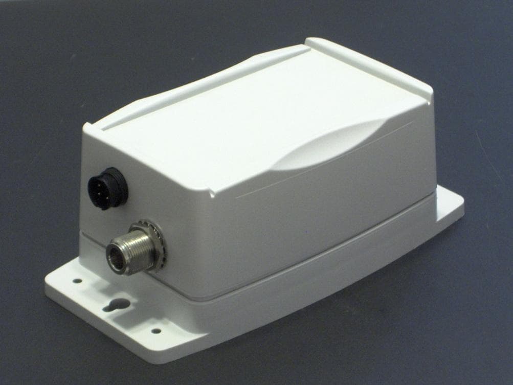
HUB: X9INCS02010910 The HUB is designed such that the UMC RF connector on the board outputs to an antenna (SMA connector) on the outside of the enclosure via an internal RF plug-SMA jack coaxial cable. The antenna connector for the HUB complies with FCC part 15.203 in that the antenna uses a unique coupling to the intentional radiator. Only the antenna furnished by ELLTC shall be used with the device. IREP: X9INCS03010910 The internal repeaters are designed such that the UMC RF connector on the board outputs to an antenna (SMA connector) on the outside of the enclosure via an internal RF plug-SMA jack coaxial cable. The external antenna connector for the IREP complies with FCC Part 15.203 in that the antenna uses a unique coupling to the intentional radiator. Only the antenna furnished by ELLTC shall be used with the device. OREP: X9INCS04010910 The outdoor repeaters are designed such that the UMC RF connector on the board outputs to a Type N antenna (Type N connector) on the outside of the enclosure via an internal bulkhead-RF plug coaxial cable. The external antenna connector for the OREP complies with FCC part 15.203 in that the antenna uses a unique coupling to the intentional radiator. Only the antenna furnished by ELLTC shall be used with the device.
Parts List/Tune Up Info
HUB Device Item QTYDes i g n at o r Des c r i p t i o n 1 M an u f ac t u r er M an u f ac t u r er Par t Nu m b er So u r c e/Rep /Di s t 11ANT1 1 Stage 15dB SMT Mount Active GPS Patch Antenna TaoglasAP.10C.01Arrow 21BT1 BATTERY LITHIUM 3.1V RECHARGE Seiko InstrumentsMS518SE-FL35ESeiko 31C1 CAP 2200PF 25V CERAMIC 0402 SMD Panasonic - ECGECJ-0EB1E222KArrow 45C4, C5, C46, C47, C221 CAP 22PF 50V CERAMIC 0402 SMD Panasonic - ECGECJ-0EC1H220JArrow 53C7, C201, C214 CAP CER 47PF 50V NP0 0402 Johanson Dielectrics Inc500R07N470JV4TArrow 615 C10, C12, C15, C17, C19, C22, C24, C26, C28, C30, C32, C40, C42, C115, C222CAP .1UF 10V CERAMIC X5R 0402 Panasonic - ECGECJ-0EB1A104KArrow 73C11, C21, C34 CAP CERAMIC 10UF 10V 0603 X5R Panasonic - ECGECJ-1VB1A106MArrow 85C13, C35, C37, C39, C41 CAP CER 4.7UF 10V Y5V 0603 Murata Electronics North AmericaGRM188F51A475ZE20DArrow 912 C14, C16, C18, C20, C23, C25, C27, C29, C31, C33, C36, C38CAP CERAMIC 1UF 10V X5R 0402 Panasonic - ECGECJ-0EB1A105MArrow 101C44 CAP .01UF 25V CERAMIC X7R 0402 Panasonic - ECGECJ-0EB1E103KArrow 116C45, C100, C101, C202, C203, C208 CAP 100PF 50V CERAMIC 0402 SMD Panasonic - ECGECJ-0EC1H101JArrow 121C114 CAP CER 5.1PF 50V C0G 0402 Murata Electronics North AmericaGRM1555C1H5R1DZ01DArrow 135C116, C204, C212, C213, C215 CAP CER 33PF 25V S 0402 UHI Q Johanson Technology Inc250R07S330GV4TArrow 142C205, C207 CAP CER 3.6PF 50V S 0402 UHI Q Johanson Technology Inc500R07S3R6BV4TArrow 151C206 CAP CER 6.2PF 50V S 0402 UHI Q Johanson Technology Inc500R07S6R2CV4TArrow 162C209, C226 CAP 10000PF 16V CERAMIC 0402 SMD Panasonic - ECGECJ-0EB1C103KArrow 171C210 CAP 1000PF 25V CERAMIC 0402 SMD Panasonic - ECGECJ-0EB1E102KArrow 184C211, C223, C224, C225 CAP 27PF 50V CERAMIC 0402 SMD Panasonic - ECGECJ-0EC1H270JArrow 191C216 CAP CER 10PF 50V S 0402 UHI Q Johanson Technology Inc500R07S100JV4TArrow 201C217 CAP CER 5.6PF 50V S 0402 UHI Q Johanson Technology Inc500R07S5R6CV4TArrow 211C218 CAP CER 3.3PF 50V S 0402 UHI Q Johanson Technology Inc500R07S3R3BV4TArrow 221C219 CAP 1.5PF 50V CERAMIC 0402 SMD Panasonic - ECGECJ-0EC1H1R5CArrow 231C220 CAP CER 10UF 16V X5R 20% 0805 AVX Corporation0805YD106MAT2AArrow 241C227 CAP CER 15PF 50V S 0402 UHI Q Johanson Technology Inc500R07S150JV4TArrow 253D4, D5 DIODE SCHOTTKY 500MA 20V 0603 Comchip TechnologyCDBU0520Arrow 261D6 DIODE SW 250MA 80V 150W SOT-523 Micro Commercial CoMMBD4448HT-TPArrow 271FB200 FERRITE CHIP 30 OHM 2200MA 0402 Murata Electronics North AmericaBLM15PD300SN1DArrow 282FLT200, FLT201 FILTER SAW ISM 915MHZ RFID SMD Murata Electronics North AmericaSAFEB915MAL0F00R12Arrow 291J1 CONN JACK UMC VERTICLE SMDEmerson Network Power Connectivity Solutions 128-0711-201Arrow 301J3 CONN HEADER VERT SGL 5POS GOLD 3M961105-0711-201Molex 311J4 ITW PANCON - JSA41G0 - Jumper Switch ITW PANCONJSA41G0Arrow 323L1, L2, R23 RES 0.0 OHM 1/16W 5% 0402 SMD, RES 0.0 OHM 1/16W 0402 SMD YageoRC0402JR-070RLArrow 333L201, L202, L206 INDUCTOR 10NH 500MA 0402 Murata Electronics North AmericaLQW15AN10NJ00DArrow 341L203 INDUCTOR 11NH .64A WW 0402 Wurth Electronics Inc744765111AArrow 351L204 CER INDUCTOR 27NH 0402 Johanson Technology IncL-07C27NJV6TArrow 361L205 CER INDUCTOR 2.2NH 0402 Johanson Technology IncL-07C2N2SV6TArrow 371L207 INDUCTOR MULTILAYER 1.6NH 0402 TDK CorporationMLG1005S1N6SArrow 381L208 CER INDUCTOR 15NH 0402 Johanson Technology IncL-07C15NJV6TArrow 391LS1 BUZZER MAGNETIC 3V 5MM SMD PUI AudioSMT-0540-S-RPUI Audio 401MD1 MODULE GPS Wi2Wi W 2SG0006-006F-11W W Roy Zappia 411MD100 MOD 802.15.4/ZIGB 900MHZ RF OUT PanasonicENW-59611N3AArrow 421MP1RF Shield, 27.89 x 17.96 x 2.5 mm (48 MHz)GenesisGTI09-60347 Rev6Ken Erickson 431MP2RF Shield, 18.97 x 23.47 x 2.5 mm (900 MHz)GenesisGTI09-60348 Rev5Ken Erickson 441P2 CONN HEADER 3POS 1.25MM VERT SMD Molex Connector Corporation53398-0371Arrow 451P3 SAMTEC - FTSH-105-01-L-DV-K - .050 X .050 SAMTECFTSH-105-01-L-DV-KArrow 465P4, P5, P6, P7, P8 CONN HEADER 2POS .100 VERT GOLD Molex Connector Corporation22-29-2021Arrow 471P200 CONN RECEPT COAX SWITCHING SMT Hirose Electric Co LtdMS-147(06)Arrow 483Q1, Q2, Q3 MOSFET N-CH 20V 200MA 3-DFN Diodes IncDMN2005LP4K-7Arrow 491Q4 MOSFET P-CH 20V 1.5A 3-DFN Diodes IncDMP2104LP-7Arrow 501Q5 MOSFET P-CH 20V 3.7A SOT23-3 Vishay/SiliconixSI2323DS-T1-E3Arrow 511R2 RES 174K OHM 1/10W 1% 0402 SMD Panasonic - ECGERJ-2RKF1743XArrow 526R3, R42, R100, R101, R200, R202 RES 1.0K OHM 1/16W 5% 0402 SMD Rohm SemiconductorMCR01MZPJ102Arrow 533R7, R201, R203 RES 0.0 OHM 1/16W 5% 0402 SMD Rohm SemiconductorMCR01MZPJ000Arrow 541R8 RES 20K OHM 1/10W 5% 0402 SMD Panasonic - ECGERJ-2GEJ203XArrow 551R10 RES 2.10K OHM 1/10W 1% 0402 SMD Panasonic - ECGERJ-2RKF2101XArrow 561R11 RES 71.5K OHM 1/10W 1% 0402 SMD Panasonic - ECGERJ-2RKF7152XArrow 576R12, R25, R26, R27, R28, R30 RES 10K OHM 1/10W 5% 0402 SMD Panasonic - ECGERJ-2GEJ103XArrow 581R13 RESISTOR 1.0 OHM 1/10W 5% 0603 Panasonic - ECGERJ-3GEYJ1R0VArrow 592R14, R15 RES 27.0 OHM 1/10W 1% 0402 SMD Panasonic - ECGERJ-2RKF27R0XArrow 601R16 RES 100K OHM 1/10W 5% 0402 SMD Panasonic - ECGERJ-2GEJ104XArrow 611R17 RES 1.00M OHM 1/10W 1% 0402 SMD Panasonic - ECGERJ-2RKF1004XArrow 621R18 RES 3.74M OHM 1/16W 1% 0402 SMDVishay/DaleCRCW 04023M74FKED Arrow 633R20, R21, R22 RES 300 OHM 1/10W 5% 0402 SMD Panasonic - ECGERJ-2GEJ301XArrow 641R24 RES 249K OHM 1/10W 1% 0402 SMD Panasonic - ECGERJ-2RKF2493XArrow 651R31 RES 200 OHM 1/10W 5% 0402 SMD Panasonic - ECGERJ-2GEJ201XArrow 661R36 RES 82 OHM 1/10W 5% 0603 SMD Panasonic - ECGERJ-3GEYJ820VArrow 671R37 RES 59.0 OHM 1/10W 1% 0603 SMD Panasonic - ECGERJ-3EKF59R0VArrow 682R40, R41 RES 5.1K OHM 1/10W 5% 0402 SMD Panasonic - ECGERJ-2GEJ512XArrow 691R43 RES 270 OHM 1/10W 5% 0603 SMD Panasonic - ECGERJ-3GEYJ271VArrow 702R204, R205 RES 120 OHM 1/10W 5% 0402 SMD Panasonic - ECGERJ-2GEJ121XArrow 711SEN1 Omnidirectional Tilt and Vibration Sensor SignalQuest Precision MicrosensorsSQ-SEN-200SignalQuest 721SW1 SWITCH TACT SPST W/O GND SMD Omron Electronics Inc-ECB DivB3U-1000PArrow 731SW2 SWITCH LIGHT TOUCH 1…
Text truncated - open the document above for the full version.
RF Exposure Info
Report Number: 11CA14739-Hub File Number: MC16660 Page 1 of 3 Model Number: Hub Client Name: Elliott Tech, LLC (FCC ID: X9INCS02010910) Page 1 of 3 1.1 Test Conditions and Results – MAXIMUM PERMISSIBLE EXPOSURE Test Description Maximum Permissible Exposure calculation is performed to ensure that this device meets RF exposure limits for its intended environment. This device is required to meet the General Population/Uncontrolled exposure limits. Basic Standard 47 CFR Part 1.1307 Industry Canada IC Safety Code 6 FCC Limits for Occupational/Controlled Exposure Frequency Range (MHZ) Electric Field Strength (E) (V/M) Magnetic Field Strength (H) (A/M) Power Density (S) (MW/CM 2 ) Averaging Time E 2 , H 2 . or S (MINUTES) 0.3 – 3.0 614 1.63 (100)* 6 3.0 - 30 1824/F 4.89/F (900/F 2 )* 6 30 - 300 61.4 0.163 1.0 6 300 – 1500 - - F/300 6 1500 – 100,000 - - 5.0 6 FCC Limits for General Population/Uncontrolled Exposure Frequency Range (MHz) Electric Field Strength (E) (V/m) Magnetic Field Strength (H) (A/m) Power Density (S) (mw/cm 2 ) Averaging Time E 2 , H 2 . or S (minutes) 0.3 - 1.34 614 1.63 (100)* 30 1.34 - 30 824/F 2.19/F (180/F 2 )* 30 30 - 300 27.5 0.073 0.2 30 300 – 1500 - - F/1500 30 1500 – 100,000 - - 1.0 30 Figure 1 MPE - EUT Configuration Settings Calculation is performed from conducted power and antenna gain measurements documented within this report. Report Number: 11CA14739-Hub File Number: MC16660 Page 2 of 3 Model Number: Hub Client Name: Elliott Tech, LLC (FCC ID: X9INCS02010910) Page 2 of 3 Background: Per the following guidance from OET Bulletin 65 Supplement C required minimum spacings are provided to the professional installer. Transmitter or Device Type 18 Output 19 Applicable Methods to Ensure Compliance 20 Transmitters using indoor antennas that operate at 20 cm or more from nearby persons >2.5 W at 915 MHz If the MPE distance is greater than that required for normal operation of the device, operating instructions, warning instructions and/or warning labels may be used to ensure compliance by indicating the minimal separation distance to comply with MPE limits. If the antennas are professionally installed to ensure compliance, warning instructions and warning labels are not necessary. = 2.5 W at 915 MHz or =< 4 W at 2450 MHz Transmitters operating at 2.5 W EIRP (1.5 W ERP) or less at 915 MHz, or at 4 W EIRP (2.4 W ERP) or less at 2450 MHz, generally are not expected to exceed MPE limits when nearby persons are 20 cm or more from most antennas. Therefore, special instructions and warnings are normally not necessary to ensure compliance. Figure 2 Duty Cycle Correction Factor Mode ON Duration (ms) Total Duration (ms) Duty Cycle Correction (dB) )log(20 100 )( ms msTX Comments Short Pulse 14 101.4 Long Transmission 38 171.6 Total 52 273.0 -14.4 dB 52ms / 273ms = 19.0% Report Number: 11CA14739-Hub File Number: MC16660 Page 3 of 3 Model Number: Hub Client Name: Elliott Tech, LLC (FCC ID: X9INCS02010910) Page 3 of 3 Figure 3 MPE - Calculation MPE Calculation with highest EIRP: The highest conducted power was observed to be 617 mW and this measurement is used for the calculation. Limit is calculated at low channel (902.5 MHz) as exposure limit increases slightly with frequency in the operating band. Duty cycle is 14.4%. S = EIRP / (4 * Pi * R 2 ), Power Density = EIRP / (4 * Pi * R 2 ), where EIRP = Output Power * Antenna Gain Uncontrolled/General Exposure 0.617 Watt, 0.00 dBi antenna (Unity Gain), 20 cm spacing Operating Frequency 902.5 MHz Output Power (Peak) 0.617 Watts Antenna Gain 0.0 dB or (linear) 1.000(unitless) Separation Distance 0.2 m -or- 7.874inches Peak Power Density 1.227 W/m 2 - or - 0.1227mW/cm 2 Exposure % (over 6 min timespan for uncontrolled) 100% Transmit Duty Cycle (Peak-to-Average Ratio) 14.4% Average Power Density 0.1767 W/m 2 - or - 0.01767 mW/cm 2 Limit for Uncontrolled Exposure at Operating Frequenc…
Text truncated - open the document above for the full version.
Contact Information
Applicant
Greg Williams(Owner)
Test Firm
UL LLCRick Titus
Technical Specifications
| # | Rule Parts | Frequency Range | Power Output |
|---|---|---|---|
| 1 | 15C | 902.5 MHz - 927.5 MHz | 640.00 mW |
Other Applications from New Centurion Solutions, Inc.
X9INCS04010910
Apr 18, 2011HANDHELD SECURITY DEVICE
Equipment Class
DSS - Part 15 Spread Spectrum Transmitter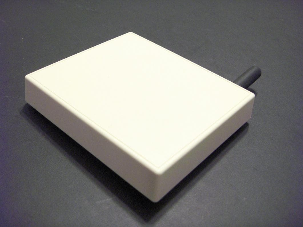
X9INCS03010910
Apr 18, 2011HANDHELD SECURITY DEVICE
Equipment Class
DSS - Part 15 Spread Spectrum Transmitter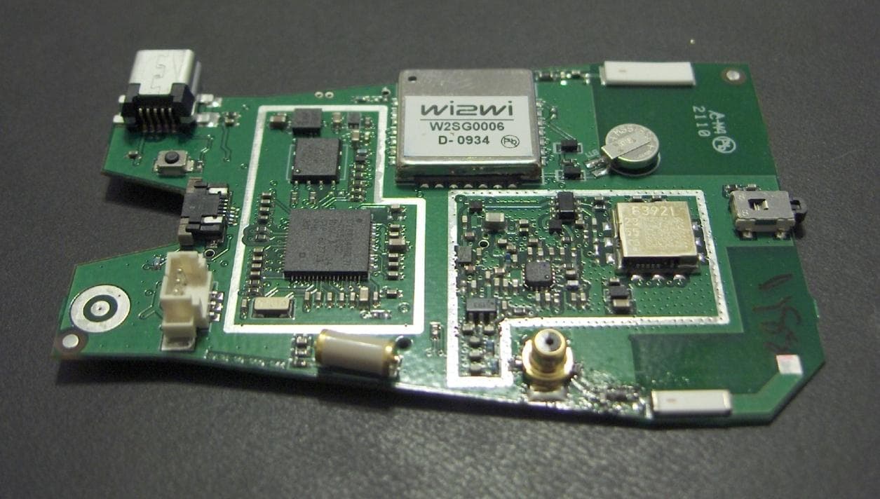
X9INCS01010910
Apr 12, 2011HANDHELD SECURITY DEVICE
Equipment Class
DSS - Part 15 Spread Spectrum Transmitter