XBI19003200Cloud Digital Photo Frame
SUNGALE ELECTRONICS (SHENZHEN) CO., LTD.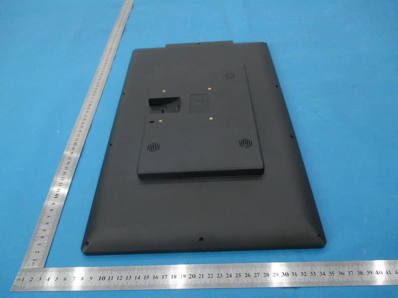
Click to zoom
Application Details
- Equipment Class
- DTS - Digital Transmission System
- Date of Grant
- Jan 20, 2015
- Application Purpose
- Original Equipment
- Date of Application
- Jan 20, 2015
- Equipment Note
- Cloud Digital Photo Frame
- Frequency Range
- 2412.00000000 - 2462.00000000
- Country
- China
Documents & Files
Document Text
Text extracted from the exhibit documents filed with the FCC. Open a document above to read the original.
Users Manual
User's Manual For ongoing product improvement, this manual is subject to modification without prior notice. Cloud Digital Photo Frame MODEL: CD1900WV FCC ID:XBI19003200 Before Operation Product Introduction Safety Precautions 2 3 5 Package Contents 7 7 Basic Operation Insert a memory card 8 Connect to the computer 9 9 11 Advanced Operation 12 13 14 12 18 18 Customer Management Support FAQs Remote Control illustration 5 8 Getting Started Connect Power Start-Up & Navigation Dual Interface 10 Status Icon Briefing WiFi Setup Google Account Google Play Store Online Photos Online Videos 15 15 Social Media LAN Photos & Videos 16 16 Local Photos Local Videos 17 Settings Menu Overview 18 Tips 14" WiFi Digital Photo Frame, share your favorite photos and videos from the internet with friends, family and places of business, and bring endless photo and video storage with easy navigation to your home or business. Features: Specifications: Display resolution : 1366x768pixels (16:9) Display size: 19 inch LED Internal memory: 8GB Multimedia support: Photo / Video / Audio Built-in WiFi : 802.11 b/g/n Memory Card: SD/SDHC Speakers: 2 x 2W G-sensor: Yes USB type: 1xMini USB OTG, 1x USB host Power Adaptor: Input: 110~240V; Output: 12V, 2A Product Introduction Before Operation 2 Build up your own cloud albums, manage remote frames slide shows Enjoy 10GB free cloud storage space. View photos you stored in your cloud storage View photos scattered in computers in your home LAN View photos stored in you SD cards Store your most precious photos in internal memory and display them Share photos with your family and friends via internet Support display multimedia Dual interface, modern and traditional, for your selection High resolution screen to show details of the photos Motion sensor remote controller eases your internet surfing Wireless link to internet automatically Remote: Motion Sensor RC Safety Precautions Before Operation 3 Before Operation Safety Precautions 4 5 Before Operation Package Contents 19” Cloud Digital Photo Frame Quick Start Guide Remote Control Power Adaptor Stand Limited Warranty Remote Control Power on/off Volume DownVolume Up Enter Back Home screen Key Lock Page up Mute Menu Up (Direction key) Down (Direction key) Left (Direction key) Right (Direction key) Page down Tip: Click the button to lock screen, and press again to unlock screen. Note: Insert remote control receiver in the USB port before you use the remote control. Before Operation 6 Motion Sensor Remote illustration Open battery compartment, you will see a mini receiver, plug the mini receiver into the USB port, put in batteries, close compartment. Then click the button on the remote control, now, you can use your motion sensor remote. The Mini receiverTake out the Mini receiver Plug the mini receiver into the USB port Put in 2 AAA batteries into the Remote Control Basic Operation 7 Getting Started Connect Power Your frame can either sit on the top of a surface with the stand or hang on the wall with the optional support (not included) Plug the Power Adaptor into the frame and also into a Power Outlet. Wall mounting hole (The wall mounting support is not included) Sitting on top of a surface hang on a wall Use the USB cable, you can connect the Cloud DPF to the computer Basic Operation Connect the Cloud DPF to the computer 8 SD/SDHC card is compatible with this unit. SD/SDHC Insert a memory card 9 Basic Operation Dual Interface To switch between interface, Hold the “OK” key to slash cursor on home screen. Block InterfaceTraditional Interface Status Icon Briefing Social Media: reach to facebook, twitter or google play's login page. Settings: Configure the unit. Have four icons in this route: Browser, all Apps, Files, Settings. Online Videos: to review or download videos from website. Local Videos: Play or view the videos stored in internal memory, SD card, U-Disk. LAN Photos: to share or review the photos in local internet. LAN Videos: to share or review the videos in local internet. Local Photos: Display or review the photos stored in internal memory, SD card, U-Disk. Online Photos: to review or download photos from website. Dropbox:to connect with other DPF or mobile to share the pictures 10 Basic Operation 1 4 23 8 9 10 7 2 3 4 5 6 7 8 9 MY Cloud Album: to share or review the photos in cloud storage space. 1 5 6 10 11 Advanced Operation WiFi Setup Step 2. Select the “SETTINGS” menu icon. Slide the WiFi button to the “ON” position. Select your network, put in your password, and than click “connect”. Note: In order to use the online featuresof this frame, you must connect your frame to a WiFi internet connection. Step 3. Step 4. Step 1. To setup the WiFi Connection on your photo frame, click “SETTINGS” from the home screen. (Cont. Next page) Advanced Operation 12 Step 1. Online Account Setup Part 1: Google Account A Google Account will allow you to access the Google Play Store for APP downloads, and Google applications. Step 2. Step 3. Go to the Settings menu, and scroll down to “+Add account”, and click it. Click “Google” under the add an account menu. Click “Existing” if you currently have a gmail email account and put in your email and password. Click “New” to setup a gmail email account. Google Play Store Once you have setup your Google Account, you can access Google Play. Advanced Operation 13 Online Account Setup Part 2: Online Photos To access these Photo Hubs select Online Photos. Select the “+” symbol in the lower right corner to enter the online storage back list. Select“YES” to download The Online Photos tab gives you access to a numerous amount of online Photo Hubs. Select any Hub to install and download to your frame. Select“YES” to install After the installation is complete, your Hub will be available on the front screen. You can now select and use it. 14 Advanced Operation Online Account Setup Part 3: Online Videos To access these Video Hubs select Online Videos. Select the “+” symbol in the lower right corner to ente…
Text truncated - open the document above for the full version.
Cover Letter(s)
Ersteller: D. Brandhorst Revision: 00 Erstelldatum: 21.06.07 Datum: 00.00.00 Seite 1 von 1 Date: Dec. 19, 2014 Subject: Ad Hoc Mode Function Declaration FCC ID: XBI19003200 To Whom it may concern, This device is acting as slave device and operating in the 2.4 GHz (2412 – 2462 MHz) band. Ad Hoc function is supported but not able to operate on non-US frequencies. Please contact the one signed below or the authorized agent for this filing. Thank you. Regards, SUNGALE ELECTRONICS (SHENZHEN) CO ., LTD. Contact person: Limei Wu Title: Manager
Cover Letter(s)
Dec.19, 2014 Federal Communication Commission Authorization and Evaluation Division FCC ID: XBI19003200 Re: Confidentiality Request Pursuant to Sections 0.457 and 0.459 of the Commission’s Rules, the applicant hereby requests confidential treatment of information applied this application as outlined below: 1: Block Diagram 2: Circuit Diagram 3: Parts List 4.Operational Description The above materials contain trade secrets and proprietary information not customarily released to the public. The public disclosure of these matters might be harmful to the applicant and provide unjustified benefits to its competitors. The Applicant understands that pursuant to Rules 0.457, disclosure of this Application and all accompanying documentation will not be made before the date of the Grant for this application. Sincerely, SUNGALE ELECTRONICS (SHENZHEN) CO ., LTD. Contact person: Limei Wu Title: Manager
External Photos
External Photos ALL VIEW OF EUT TOP VIEW OF EUT BOTTOM VIEW OF EUT FRONT VIEW OF EUT BACK VIEW OF EUT LEFT VIEW OF EUT RIGHT VIEW OF EUT
ID Label/Location Info
FCC ID Label Location FCC ID: XBI19003200 Trade Name: SUNGALE Model Name: CD1900WV
Internal Photos
Internal Photos OPEN VIEW OF EUT-1 INTERNAL VIEW OF EUT-1 INTERNAL VIEW OF EUT-2 Wifi Antenna INTERNAL VIEW OF EUT-3 INTERNAL VIEW OF EUT-4 INTERNAL VIEW OF EUT-4 INTERNAL VIEW OF EUT-5 INTERNAL VIEW OF EUT-6
Test Report
Page 1 of 69 Report No.: AGC00074141101FE01 FCC ID : XBI19003200 APPLICATION PURPOSE : Original Equipment PRODUCT DESIGNATION : Cloud Digital Photo Frame BRAND NAME : SUNGALE MODEL NAME : Refer to page 5 CLIENT : SUNGALE ELECTRONICS (SHENZHEN) CO., LTD. DATE OF ISSUE : Dec.15, 2014 STANDARD(S) TEST PROCEDURE(S) : FCC Part 15.247 KDB 558074 v03r02 REPORT VERSION : V1.0 Attestation of Global Compliance (Shenzhen) Co., Ltd CAUTION: This report shall not be reproduced except in full without the written permission of the test laboratory and shall not be quoted out of context. FCC Test Report Report No.: AGC00074141101FE01 Page 2 of 69 Report Revise Record Report Version Revise Time Issued Date Valid Version Notes V1.0 / Dec.15, 2014 Valid Original Report Report No.: AGC00074141101FE01 Page 3 of 69 TABLE OF CONTENTS 1. VERIFICATION OF CONFORMITY ...................................................................................... 5 2. GENERAL INFORMATION .................................................................................................. 6 2.1. PRODUCT DESCRIPTION ........................................................................................................... 6 2.2. TABLE OF CARRIER FREQUENCYS .......................................................................................... 6 2.3. IEEE 802.11N MODULATION SCHEME ...................................................................................... 7 2.4. RELATED SUBMITTAL(S) / GRANT (S) ....................................................................................... 7 2.5. TEST METHODOLOGY................................................................................................................ 7 2.6. SPECIAL ACCESSORIES ............................................................................................................ 7 2.7. EQUIPMENT MODIFICATIONS ................................................................................................... 7 3. MEASUREMENT UNCERTAINTY........................................................................................ 8 4. DESCRIPTION OF TEST MODES ........................................................................................ 8 5. SYSTEM TEST CONFIGURATION ...................................................................................... 9 5.1. CONFIGURATION OF EUT SYSTEM .......................................................................................... 9 5.2. EQUIPMENT USED IN EUT SYSTEM ......................................................................................... 9 5.3. SUMMARY OF TEST RESULTS .................................................................................................. 9 6. TEST FACILITY .................................................................................................................. 10 7. OUTPUT POWER ............................................................................................................... 11 7.1. MEASUREMENT PROCEDURE ................................................................................................ 11 7.2. TEST SET-UP (BLOCK DIAGRAM OF CONFIGURATION) ....................................................... 11 7.3. LIMITS AND MEASUREMENT RESULT .................................................................................... 12 8. 6DB BANDWIDTH .............................................................................................................. 14 8.1. MEASUREMENT PROCEDURE ................................................................................................ 14 8.2. TEST SET-UP (BLOCK DIAGRAM OF CONFIGURATION) ....................................................... 14 8.3. LIMITS AND MEASUREMENT RESULTS .................................................................................. 15 9. CONDUCTED SPURIOUS EMISSION ............................................................................... 23 9.1. MEASUREMENT PROCEDURE ................................................................................................ 23 9.2. TEST SET-UP (BLOCK DIAGRAM OF CONFIGURATION) ....................................................... 23 9.3. MEASUREMENT EQUIPMENT USED ....................................................................................... 23 9.4. LIMITS AND MEASUREMENT RESULT .................................................................................... 23 10. MAXIMUM CONDUCTED OUTPUT AVERAGE POWER SPECTRAL DENSITY ........... 26 10.1 MEASUREMENT PROCEDURE ............................................................................................... 26 10.2 TEST SET-UP (BLOCK DIAGRAM OF CONFIGURATION) ...................................................... 26 10.3 MEASUREMENT EQUIPMENT USED ...................................................................................... 26 10.4 LIMITS AND MEASUREMENT RESULT ................................................................................... 26 Report No.: AGC00074141101FE01 Page 4 of 69 11. RADIATED EMISSION ..................................................................................................... 34 11.1. MEASUREMENT PROCEDURE .............................................................................................. 34 11.2. TEST SETUP ............................................................................................................................ 35 11.3. LIMITS AND MEASUREMENT RESULT .................................................................................. 36 11.4. TEST RESULT .......................................................................................................................... 36 12. BAND EDGE EMISSION .................................................................................................. 49 12.1. MEASUREMENT PROCEDURE .............................................................................................. 49 12.2. TEST SET-UP .........................................…
Text truncated - open the document above for the full version.
Test Setup Photos
Test Setup Photos FCC LINE CONDUCTED EMISSION TEST SETUP FCC RADIATED EMISSION TEST SETUP
Contact Information
Applicant
Limei Wu(Quality Assistant Manager)
Test Firm
Attestation of Global Compliance Shenzhen Co. Ltd.Forrest Lei
Technical Specifications
| # | Rule Parts | Frequency Range | Power Output |
|---|---|---|---|
| 1 | 15C | 2.41 GHz - 2.46 GHz | 9.40 mW |
Other Applications from SUNGALE ELECTRONICS (SHENZHEN) CO., LTD.
XBI9821036
Jul 14, 2013MID
Equipment Class
DTS - Digital Transmission System
XBI8101019
Jun 04, 2013MID
Equipment Class
DTS - Digital Transmission System
Apr 29, 2012
Equipment Class
JBP - Part 15 Class B Computing Device Peripheral