XENBLTX-BTBluetooth Keyboard
Heng Yu Electronic Manufacturing Co. Ltd.
Click to zoom
Application Details
- Equipment Class
- DTS - Digital Transmission System
- Date of Grant
- Dec 17, 2020
- Application Purpose
- Original Equipment
- Date of Application
- Dec 17, 2020
- Equipment Note
- Bluetooth Keyboard
- Frequency Range
- 2402.00000000 - 2480.00000000
- Country
- China
Documents & Files
Document Text
Text extracted from the exhibit documents filed with the FCC. Open a document above to read the original.
Users Manual
How to pair the Bluetooth Keyboard with PC 1. Go to “Setting” in the Windows and select “Bluetooth and other device”, select “add Bluetooth or other devices” 2. In the prompt out window, select “Bluetooth” 3. Pressing “Fn + ESC” to switch the keyboard into Bluetooth pairing mode, indicator LED will flash. 4. On the PC side, in the prompt out window, the PC should be able to find a device called “BLTBT”, please select the “BLTBT”. 5. A window will prompt out for showing a pairing code, please type exactly the provided code on the keyboard as shown in the window and then press the “Enter” on the keyboard to confirm the pairing. 6. After the Step 5, indicator LED will stop flashing, the keyboard should be able to show up in the “Mouse, keyboard, & pen” category, now the keyboard is connected to the target PC and ready to use. Special function keys on Blt bt series Keyboard For all versions Fn + ESC = Pair Only for backlit versions Fn + Down Arrow = Decrease Backlit Brightness; Fn + UpArrow = Increase Backlit Brightness (For Wireless version, backlit will turn off to save power if there is no key stroke detected within 10 secs) Charging the Keyboard Connect the keyboard to charging dock rated at 500mA, the keyboard will start charging immediately, 5 hours is recommended for fully charging the Keyboard. NOTE: This equipment has been tested and found to comply with the limits for a Class B digital device, pursuant to part 15 of the FCC Rules. These limits are designed to provide reasonable protection against harmful interference in a residential installation. This equipment generates uses and can radiate radio frequency energy and, if not installed and used in accordance with the instructions, may cause harmful interference to radio communications. However, there is no guarantee that interference will not occur in a particular installation. If this equipment does cause harmful interference to radio or television reception, which can be determined by turning the equipment off and on, the user is encouraged to try to correct the interference by one or more of the following measures: - Reorient or relocate the receiving antenna. - Increase the separation between the equipment and receiver. -Connect the equipment into an outlet on a circuit different from that to which the receiver is connected. -Consult the dealer or an experienced radio/TV technician for help Changes or modifications not expressly approved by the party responsible for compliance could void the user's authority to operate the equipment. This device complies with Part 15 of the FCC Rules. Operation is subject to the following two conditions: (1) this device may not cause harmful interference, and (2) this device must accept any interference received, including interference that may cause undesired operation.
Cover Letter(s)
Heng Yu Electronic Manufacturing Co. Ltd. Agent Authorization Company: Heng Yu Electronic Manufacturing Co. Ltd. Address: Room 1503-5, Nan Fung Commercial Centre,19 Lam Lok Street, Kowloon Bay, Hong Kong Product Name: Bluetooth Keyboard Model Number(s): BLTX-BT Product Description: Bluetooth Keyboard We authorize MiCOM Labs Inc., 575 Boulder Court, Pleasanton, California 94566, USA, to act on our behalf on all matters concerning the certification of above named equipment. We declare that MiCOM Labs Inc. is allowed to forward all information related to the approval and certification of equipment to the regulatory agencies as required and to discuss any issues concerning the approval application. Any and all acts carried out by MiCOM Labs on our behalf shall have the same effect as acts of our own. Signature: Date: 2020-12-14 Name: H.K. Chan Company: Heng Yu Electronic Manufacturing Co. Ltd.
Cover Letter(s)
Heng Yu Electronic Manufacturing Co. Ltd. Office of Engineering Technology Federal Communications Commission 7435 Oakland Mills Road Columbia, MD 21046 USA Date: 2020-12-14 Subject; Request for Confidentiality FCC ID: XENBLTX-BT To Whom It May Concern, Pursuant to the provisions of the Commission’s rules Title 47 Sections §0.457 and §0.459, we are requesting the Commission to withhold the following attachment(s) as confidential documents from public disclosure indefinitely. These documents contain detailed system and equipment descriptions and are considered as proprietary information in operation of the equipment. The public disclosure of these documents might be harmful to our company and would give competitors an unfair advantage in the market. Schematic Diagram Block Diagram Parts List Operational Description Tune-up Procedure In additional to above mentioned documents, in order to comply with the marketing regulations in Title 47 CFR §2.803 and the importation rules in Title 47 CFR §2.1204, while ensuring that business sensitive information remains confidential until the actual marketing of newly authorized devices, we request Short Term Confidentiality of the following attachment(s); External Photos Test Setup Photos Internal Photos User Manual For 45 days, pursuant to Public Notice DA 04-1705. OR For 180 days pursuant to KDB 726920 D01. It is our understanding that all measurement test reports, FCC ID label format and correspondence during the certification review process cannot be granted as confidential documents and this information will be available for public review once the grant of equipment authorization is issued. Sincerely Heng Yu Electronic Manufacturing Co. Ltd. Contact person: H.K. Chan
External Photos
External Photos WHOLE VIEW OF EUT-1 WHOLE VIEW OF EUT-2 TOP VIEW OF EUT BOTTOM VIEW OF EUT FRONT VIEW OF EUT BACK VIEW OF EUT LEFT VIEW OF EUT RIGHT VIEW OF EUT VIEW OF EUT(PORT) Charging Dock TOP VIEW OF EUT BOTTOM VIEW OF EUT FRONT VIEW OF EUT BACK VIEW OF EUT LEFT VIEW OF EUT RIGHT VIEW OF EUT VIEW OF EUT(PORT)-1 VIEW OF EUT(PORT)-2
ID Label/Location Info
FCC ID Label Location FCC ID: XENBLTX-BT
Internal Photos
Internal Photos OPEN VIEW OF EUT INTERNAL VIEW OF EUT-1 INTERNAL VIEW OF EUT-2 INTERNAL VIEW OF EUT-3 INTERNAL VIEW OF EUT-4 INTERNAL VIEW OF EUT-5 INTERNAL VIEW OF EUT-6 INTERNAL VIEW OF EUT-7 INTERNAL VIEW OF EUT-8 INTERNAL VIEW OF EUT-9 INTERNAL VIEW OF EUT-10 BT Antenna INTERNAL VIEW OF EUT-11 INTERNAL VIEW OF EUT-11 Charging Dock OPEN VIEW OF EUT INTERNAL VIEW OF EUT-1 INTERNAL VIEW OF EUT-2
RF Exposure Info
RF EXPOSURE EVALUATION 1. PRODUCT INFORMATION Product Description Bluetooth Keyboard Model Name BLTX-BT FCC ID XENBLTX-BT 2. EVALUATION METHOD According to 447498 D01 General RF Exposure Guidance v05 The 1-g and 10-g SAR test exclusion thresholds for 100 MHz to 6 GHz at test separation distances ≤ 50 mm are determined by: [(max. power of channel, including tune-up tolerance, mW)/(min. test separation distance, mm)] ·[√f(GHz)] ≤ 3.0 for 1-g SAR and ≤ 7.5 for 10-g extremity SAR. Where f(GHz) is the RF channel transmit frequency in GHz Power and distance are rounded to the nearest mW and mm before calculation 3. CALCULATION P t =-1.567dBm=0.70mW The value of the Maximum output power P t is referred to the test report of the CFR47 §15.247. The result for RF exposure evaluation SAR=(0.70mW /5mm) .[√2.480GHz)]= 0.22<3.0 for 1-g SAR and ≤ 7.5 for 10-g extremity SAR. 4. CONCLUSION The SAR evaluation is not required.
Test Report
Page 1 of 56 FCC Test Report Report No.: AGC07846200301FE02 FCC ID : XENBLTX-BT APPLICATION PURPOSE : Original Equipment PRODUCT DESIGNATION : Bluetooth Keyboard BRAND NAME : Heng Yu MODEL NAME : BLTX-BT APPLICANT : Heng Yu Electronic Manufacturing Co. Ltd. DATE OF ISSUE : Apr. 14, 2020 STANDARD(S) : FCC Part 15.247 REPORT VERSION : V1.0 Attestation of Global Compliance (Shenzhen) Co., Ltd CAUTION: This report shall not be reproduced except in full without the written permission of the test laboratory and shall not be quoted out of context. Report No.: AGC07846200301FE02 Page 2 of 56 REPORT REVISE RECORD Report Version Revise Time Issued Date Valid Version Notes V1.0 / Apr. 14, 2020 Valid Initial Release Report No.: AGC07846200301FE02 Page 3 of 56 TABLE OF CONTENTS 1. VERIFICATION OF COMPLIANCE ............................................................................................................... 5 2. GENERAL INFORMATION ............................................................................................................................ 6 2.1. PRODUCT DESCRIPTION .................................................................................................................... 6 2.2.TABLE OF CARRIER FREQUENCYS .................................................................................................... 6 2.3. RELATED SUBMITTAL(S)/GRANT(S) ................................................................................................... 7 2.4.TEST METHODOLOGY .......................................................................................................................... 7 2.5. SPECIAL ACCESSORIES ..................................................................................................................... 7 2.6. EQUIPMENT MODIFICATIONS ............................................................................................................. 7 3. MEASUREMENT UNCERTAINTY ................................................................................................................. 8 4. DESCRIPTION OF TEST MODES ................................................................................................................. 9 5. SYSTEM TEST CONFIGURATION ............................................................................................................. 10 5.1 CONFIGURATION OF TESTED SYSTEM ............................................................................................ 10 5.2. EQUIPMENT USED IN TESTED SYSTEM .......................................................................................... 10 5.3. SUMMARY OF TEST RESULTS .......................................................................................................... 10 6. TEST FACILITY ............................................................................................................................................ 11 7. PEAK OUTPUT POWER ............................................................................................................................. 12 7.1. MEASUREMENT PROCEDURE .......................................................................................................... 12 7.2. TEST SET-UP (BLOCK DIAGRAM OF CONFIGURATION) ................................................................. 12 7.3. LIMITS AND MEASUREMENT RESULT .............................................................................................. 13 8. 6 DB BANDWIDTH ...................................................................................................................................... 15 8.1. MEASUREMENT PROCEDURE .......................................................................................................... 15 8.2. TEST SET-UP (BLOCK DIAGRAM OF CONFIGURATION) ................................................................. 15 8.3. LIMITS AND MEASUREMENT RESULTS ........................................................................................... 15 9. CONDUCTED SPURIOUS EMISSION ........................................................................................................ 17 9.1. MEASUREMENT PROCEDURE .......................................................................................................... 17 9.2. TEST SET-UP (BLOCK DIAGRAM OF CONFIGURATION) ................................................................. 17 9.3. MEASUREMENT EQUIPMENT USED ................................................................................................ 17 9.4. LIMITS AND MEASUREMENT RESULT .............................................................................................. 17 10. MAXIMUM CONDUCTED OUTPUT POWER SPECTRAL DENSITY ....................................................... 22 10.1. MEASUREMENT PROCEDURE ........................................................................................................ 22 10.2. TEST SET-UP (BLOCK DIAGRAM OF CONFIGURATION) ............................................................... 22 10.3. MEASUREMENT EQUIPMENT USED .............................................................................................. 22 10.4. LIMITS AND MEASUREMENT RESULT ............................................................................................ 22 11. RADIATED EMISSION ............................................................................................................................... 24 11.1. MEASUREMENT PROCEDURE ........................................................................................................ 24 Report No.: AGC07846200301FE02 Page 4 of 56 11.2. TEST SETUP ..................................................................................................................................... 25 11.3. LIMITS AND MEASUREMENT RESULT ............................................................................................ 26 11.4. TEST RESULT ...................................................................................…
Text truncated - open the document above for the full version.
Test Report
Report No.: AGC07846200301FE02 Page 45 of 56 INTERNAL VIEW OF EUT-1 INTERNAL VIEW OF EUT-2 Report No.: AGC07846200301FE02 Page 46 of 56 INTERNAL VIEW OF EUT-3 INTERNAL VIEW OF EUT-4 Report No.: AGC07846200301FE02 Page 47 of 56 INTERNAL VIEW OF EUT-5 INTERNAL VIEW OF EUT-6 Report No.: AGC07846200301FE02 Page 48 of 56 INTERNAL VIEW OF EUT-7 INTERNAL VIEW OF EUT-8 Report No.: AGC07846200301FE02 Page 49 of 56 INTERNAL VIEW OF EUT-9 INTERNAL VIEW OF EUT-10 BT Antenna Report No.: AGC07846200301FE02 Page 50 of 56 INTERNAL VIEW OF EUT-11 INTERNAL VIEW OF EUT-11 Report No.: AGC07846200301FE02 Page 51 of 56 Charging Dock TOP VIEW OF EUT BOTTOM VIEW OF EUT Report No.: AGC07846200301FE02 Page 52 of 56 FRONT VIEW OF EUT BACK VIEW OF EUT Report No.: AGC07846200301FE02 Page 53 of 56 LEFT VIEW OF EUT RIGHT VIEW OF EUT Report No.: AGC07846200301FE02 Page 54 of 56 VIEW OF EUT(PORT)-1 VIEW OF EUT(PORT)-2 Report No.: AGC07846200301FE02 Page 55 of 56 OPEN VIEW OF EUT INTERNAL VIEW OF EUT-1 Report No.: AGC07846200301FE02 Page 56 of 56 INTERNAL VIEW OF EUT-2 ----END OF REPORT---- Conditions of Issuance of Test Reports 1. All samples and goods are accepted by the Attestation of Global Compliance (Shenzhen) Co., Ltd (the “Company”) solely for testing and reporting in accordance with the following terms and conditions. The company provides its services on the basis that such terms and conditions constitute express agreement between the company and any person, firm or company requesting its services (the “Clients”). 2. Any report issued by Company as a result of this application for testing services (the “Report”) shall be issued in confidence to the Clients and the Report will be strictly treated as such by the Company. It may not be reproduced either in its entirety or in part and it may not be used for advertising or other unauthorized purposes without the written consent of the Company. The Clients to whom the Report is issued may, however, show or send it, or a certified copy thereof prepared by the Company to its customer, supplier or other persons directly concerned. The Company will not, without the consent of the Clients, enter into any discussion or correspondence with any third party concerning the contents of the Report, unless required by the relevant governmental authorities, laws or court orders. 3.The Company shall not be called or be liable to be called to give evidence or testimony on the Report in a court of law without its prior written consent, unless required by the relevant governmental authorities, laws or court orders. 4. The non-CMA report issued by AGC is only permitted to be used by the client as internal reference use and shall not be used for public demonstration purpose. 5. In the event of the improper use of the report as determined by the Company, the Company reserves the right to withdraw it, and to adopt any other additional remedies which may be appropriate. 6. Samples submitted for testing are accepted on the understanding that the Report issued cannot form the basis of, or be the instrument for, any legal action against the Company. 7. The Company will not be liable for or accept responsibility for any loss or damage however arising from the use of information contained in any of its Reports or in any communication whatsoever about its said tests or investigations. 8.Clients wishing to use the Report in court proceedings or arbitration shall inform the Company to that effect prior to submitting the sample for testing. 9. The Company is not responsible for recalling the electronic version of the original report when any revision is made to them. The Client assumes the responsibility to providing the revised version to any interested party who uses them. 10. Subject to the variable length of retention time for test data and report stored hereinto as otherwise specifically required by individual accreditation authorities, the Company will only keep the supporting test data and information of the test report for a period of six years. The data and information will be disposed of after the aforementioned retention period has elapsed. Under no circumstances shall we provide any data and information which has been disposed of after retention period. Under no circumstances shall we be liable for damage of any kind, including (but not limited to) compensatory damages, lost profits, lost data, or any form of special, incidental, indirect, consequential or punitive damages of any kind, whether based on breach of contract of warranty, tort (including negligence), product liability or otherwise, even if we are informed in advance of the possibility of such damages.
Test Setup Photos
Test Setup Photos RADIATED EMISSION TEST SETUP BELOW 1GHZ RADIATED EMISSION TEST SETUP ABOVE 1GHZ CONDUCTED TEST SETUP
Contact Information
Applicant
H.K. Chan(R&D Manager)
Technical Contact
Test Firm
Attestation of Global Compliance (Shenzhen) Co., LDoris Li
[email protected]+86-755-25234088
Technical Specifications
| # | Rule Parts | Frequency Range | Power Output |
|---|---|---|---|
| 1 | 15C | 2.40 GHz - 2.48 GHz | 700.00 µW |
Other Applications from Heng Yu Electronic Manufacturing Co. Ltd.
XENBB20
Jan 27, 2024Bump Bar
Equipment Class
DTS - Digital Transmission System
XEN-CK78
Jul 15, 2023CK78
Equipment Class
DTS - Digital Transmission System
XEN-K104R
Dec 08, 2022Keyboard
Equipment Class
DTS - Digital Transmission System
XEN-CKW
Dec 20, 2020RF Keyboard
Equipment Class
DXX - Part 15 Low Power Communication Device Transmitter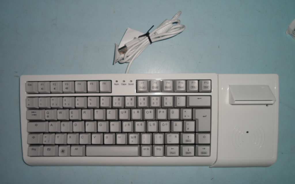
XENTA99
Oct 01, 2015Keyboard
Equipment Class
DCD - Part 15 Low Power Transmitter Below 1705 kHz