XEYVXTHERMOSTAT
VERDANT ENVIRONMENTAL TECHNOLOGIES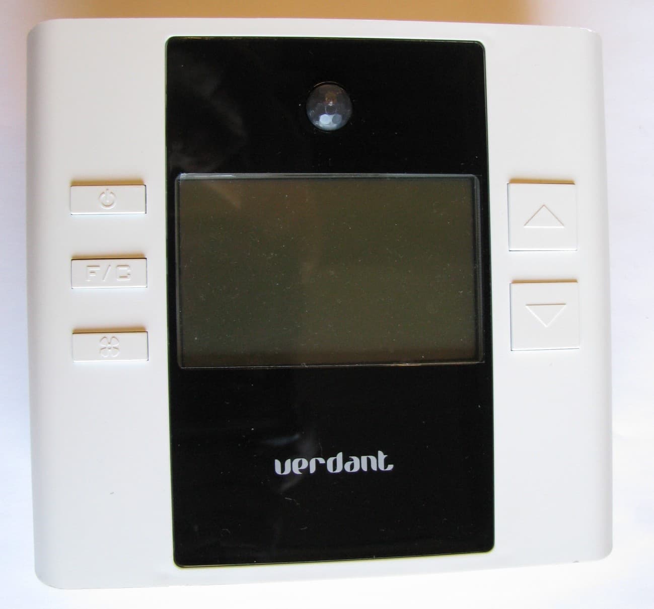
Click to zoom
Application Details
- Equipment Class
- DXX - Part 15 Low Power Communication Device Transmitter
- Date of Grant
- Sep 19, 2011
- Application Purpose
- Original Equipment
- Date of Application
- Sep 19, 2011
- Equipment Note
- THERMOSTAT
- Frequency Range
- 902.00000000 - 928.00000000
- Country
- Canada
Documents & Files
Document Text
Text extracted from the exhibit documents filed with the FCC. Open a document above to read the original.
Users Manual
VX SERIES Wireless Thermostat with Occupancy Sensor INSTRUCTION MANUAL 3 Table of Contents Thermostat Installation ...............................................................................7 Installing the Wireless Control Card ............................................................8 Mounting the thermostat to the wall .........................................................9 Thermostat Configuration .........................................................................10 Setting the thermostat clock .......................................................................11 Entering the room number .........................................................................12 Configuring the Equipment Settings - Compressor Type ...........................13 Configuring the Equipment Settings - Electric Heat ..................................14 Configuring the Equipment Settings - Reversing Valve .............................15 Configuring the Energy Saving Settings ....................................................16 Testing the thermostat ...............................................................................17 Thermostat Settings....................................................................................18 Accessing the Thermostat Settings ............................................................18 FAN ENERGY SAVINGS ................................................................................19 1 ST STAGE DIFFERENTIAL - HEAT .................................................................20 2 ND STAGE DIFFERENTIAL - HEAT ................................................................21 1ST STAGE DIFFERENTIAL - COOL................................................................22 INCIDENTAL OCCUPANCY THRESHOLD ......................................................23 FORCED 2ND STAGE HEATING ...................................................................25 NIGHT OCCUPANCY START ........................................................................26 NIGHT OCCUPANCY END ............................................................................27 TEMPERATURE RECOVERY TIME ...............................................................28 RECOVERY TEMPERATURE - HEAT ............................................................29 TEMPERATURE SETBACK DELAY - HEAT ....................................................30 MINIMUM SETBACK TEMPERATURE .........................................................31 TEMPERATURE SETBACK DELAY - COOL .....................................................32 MAXIMUM SETBACK TEMPERATURE .........................................................33 RECOVERY TEMPERATURE - COOL ............................................................34 MINIMUM SETPOINT .................................................................................35 MAXIMUM SETPOINT .................................................................................36 AUTO CHANGEOVER SETPOINT OFFSET ....................................................37 SETBACK SETPOINTS / AUTO-RESTORE ....................................................38 45 Table of Contents Troubleshooting .........................................................................................39 Thermostat is not controlling the PTAC unit. ...........................................39 Error Codes .................................................................................................40 APPENDIX 1 ..................................................................................................41 Warranty ....................................................................................................42 Technical Specifications .............................................................................44 7 Thermostat Installation BEFORE YOU BEGIN DETERMINE THE APPROPRIATE INSTALLATION LOCATION FOR THE THERMOSTAT. THE THERMOSTAT SHOULD FACE THE BED AREA OF THE ROOM. After the installation, follow the “Thermostat Configuration” Instructions to correctly configure the thermostat. For installation of a networking thermostat with remote management, refer to the “Network Installation” manual. 89 Thermostat Installation Mounting the thermostat to the wall ➤Unscrew the fixing screw and remove the thermostat cover; ➤Place the thermostat on the wall in the installation location and mark location for drilling holes for the three (3) mounting screws; ➤Drill three (3) holes in the wall and insert the three (3) wall anchors; ➤Use three (3) screws to securely mount the thermostat to the wall; ➤Insert two (2) C-cell batteries into the thermostat battery compartment; ➤Follow the “Thermostat Configuration” instructions to correctly configure the thermostat. ➤Replace the thermostat cover and screw in the fixing screw; Thermostat Installation BEFORE YOU BEGIN: Consult PTAC manufacturer’s documentation or use a voltmeter to determine if the PTAC unit outputs AC or DC power (24V). If the PTAC unit outputs AC power, make sure that the jumper on the Wireless Control Card is in the AC position - jumper is connecting “R” and “COM” pins (Default). If the PTAC unit outputs DC power, make sure that the jumper on the Wireless Control Card is in the DC position - jumper is connecting “COM” and “C” pins. Installing the Wireless Control Card ➤Unplug the PTAC unit power cord from the electrical outlet; ➤Remove the PTAC cover; ➤Set the PTAC unit to “External Thermostat” (Class 2) mode. Consult the PTAC unit documentation to determine how to set the PTAC unit to “External Thermostat” mode. ➤Connect the wires to screw terminals on the PTAC unit - refer to the Wiring Table to determine proper connections. ➤Mount the control card inside of the PTAC unit. Make sure that the Wireless Control Card antenna is not touching any metal components of the PTAC unit. Make sure that the contol card is not and cannot fall into the PTAC unit Condensation Pan. ➤Replace the PTAC front cover; ➤Plug in the PTAC unit power cor…
Text truncated - open the document above for the full version.
External Photos
APPLICANT: VERDANT ENVIRONMENTAL TECHNOLOGIES FCC ID: XEYVX EXTERNAL PHOTOS
ID Label/Location Info
TESTED TO COMPLY WITH FCC STANDARDS. THIS DEVICE COMPLIES WITH PART 15 OF THE FCC RULES. OPERATION IS SUBJECT TO THE FOLLOWING TWO CONDITIONS: (1) THIS DEVICE MAY NOT CAUSE HARMFUL INTERFERENCE, AND (2) THIS DEVICE MUST ACCEPT ANY INTERFERENCE RECEIVED, INCLUDING INTERFERENCE THAT MAY CAUSE UNDESIRED OPERATION. FCC ID: XEYVX IC: 8410A-VX MODEL(S): VX
Internal Photos
APPLICANT: VERDANT ENVIRONMENTAL TECHNOLOGIES FCC ID: XEYVX INTERNAL PHOTOS
Test Report
FCC PART 15.249 AND IC RSS-210 TEST REPORT UNLICENSED INTENTIONAL RADIATOR Applicant VERDANT ENVIRONMENTAL TECHNOLOGIES Address 5667 ROYALMOUNT AVENUE MONTREAL QUEBEC H4P 2P9 CANADA FCC ID XEYVX IC 841A-VX Model Number VX Product Description THERMOSTAT Date Sample Received 7/11/2011 Date Tested 7/26/2011 Tested By Nam Nguyen Approved By Mario de Aranzeta Report Number 1533AT11TestReport.doc Test Results PASS FAIL THE ATTACHED REPORT SHALL NOT BE REPRODUCED EXCEPT IN FULL WITHOUT THE WRITTEN APPROVAL OF TIMCO ENGINEERING, INC. 849 NW State Road 45 Newberry, FL 32669 USA Ph: 888.472.2424 or 352.472.5500 Fax: 352.472.2030 Email: [email protected] Website: www.timcoengr.com Certificate # 0955-01 APPLICANT: VERDANT ENVIRONMENTAL TECHNOLOGIES FCC ID: XEYVX IC: 8410A-VX REPORT #: V\VERDANT\1533AT11\1533AT11TestReport.doc Page 2 of 13 Mdea 9.20.2007 TABLE OF CONTENT GENERAL REMARKS ........................................................................................................................... 3 GENERAL INFORMATION.................................................................................................................... 4 EMC EQUIPMENT LIST ....................................................................................................................... 5 TEST PROCEDURES ........................................................................................................................... 6 RADIATION INTERFERENCE ............................................................................................................... 7 OCCUPIED BANDWIDTH..................................................................................................................... 9 BAND EDGE COMPLIANCE ............................................................................................................... 10 DUTY CYCLE ..................................................................................................................................... 12 POWER LINE CONDUCTED INTERFERENCE ................................................................................... 13 APPLICANT: VERDANT ENVIRONMENTAL TECHNOLOGIES FCC ID: XEYVX IC: 8410A-VX REPORT #: V\VERDANT\1533AT11\1533AT11TestReport.doc Page 3 of 13 Mdea 9.20.2007 GENERAL REMARKS The attached report shall not be reproduced except in full without the written permission of Timco Engineering Inc. Summary The device under test does: fulfill the general approval requirements as identified in this test report not fulfill the general approval requirements as identified in this test report Attestations This equipment has been tested in accordance with the standards identified in this test report. To the best of my knowledge and belief, these tests were performed using the measurement procedures described in this report. All instrumentation and accessories used to test products for compliance to the indicated standards are calibrated regularly in accordance with ISO 17025 requirements. Certificate # 0955-01 I attest that the necessary measurements were made, under my supervision, at: Timco Engineering Inc. 849 NW State Road 45 Newberry, Fl 32669 Authorized Signatory Name: Mario de Aranzeta C.E.T. Compliance Engineer/ Lab. Supervisor Date: 7/27/2011 APPLICANT: VERDANT ENVIRONMENTAL TECHNOLOGIES FCC ID: XEYVX IC: 8410A-VX REPORT #: V\VERDANT\1533AT11\1533AT11TestReport.doc Page 4 of 13 Mdea 9.20.2007 GENERAL INFORMATION DUT Specification The test results relate only to the items tested. Applicable Standard Part 15.249 DUT Description THERMOSTAT FCC ID XEYVX IC 8410A-VX Model Number VX Operating Frequency TX: (902.04 – 927.60) MHz RX: Same DUT Power Source 110–120Vac/50– 60Hz DC Power Battery Operated Exclusively Test Item Prototype Pre-Production Production Type of Equipment Fixed Mobile Portable Antenna Connector FCC Rules require that the antenna connector be unique. Test Facility Timco Engineering Inc. located at 849 NW State Road 45 Newberry, FL 32669 USA. Test Conditions Temperature: 26ºC Relative humidity: 50% Test Exercise The DUT was placed in continuous transmit mode of operation. Modifications Test Supporting Equipment Supporting Device Manufacturer Model / FCC ID Serial Number N/A APPLICANT: VERDANT ENVIRONMENTAL TECHNOLOGIES FCC ID: XEYVX IC: 8410A-VX REPORT #: V\VERDANT\1533AT11\1533AT11TestReport.doc Page 5 of 13 Mdea 9.20.2007 EMC EQUIPMENT LIST Device Manufacturer Model Serial Number Cal/Char Date Due Date 3-Meter Semi- Anechoic Chamber Panashield N/A N/A Listed 3/10/10 3/10/12 AC Voltmeter HP 400FL 2213A14499 CAL 3/23/09 3/23/12 Antenna: Dipole Kit Electro- Metrics TDA-30/1-4 153 CHAR 6/10/09 6/10/12 Frequency Counter HP 5385A 3242A07460 CAL 5/26/09 5/26/12 Hygro- Thermometer Extech 445703 0602 CAL 1/30/09 1/30/12 Modulation Analyzer HP 8901A 3435A06868 CAL 5/26/09 5/26/12 Digital Multimeter Fluke FLUKE-77-3 79510405 CAL 5/18/09 5/18/12 Analyzer Tan Tower Preamplifier HP 8449B-H02 3008A00372 CAL 11/21/09 11/21/11 Analyzer Tan Tower Quasi- Peak Adapter HP 85650A 3303A01690 CAL 11/22/09 11/22/11 Analyzer Tan Tower RF Preselector HP 85685A 3221A01400 CAL 11/21/09 11/21/11 Analyzer Tan Tower Spectrum Analyzer HP 8566B Opt 462 3138A07786 3144A20661 CAL 11/24/09 11/24/11 Temperature Chamber Tenney Engineering TTRC 11717-7 CHAR 4/25/10 4/25/12 APPLICANT: VERDANT ENVIRONMENTAL TECHNOLOGIES FCC ID: XEYVX REPORT: V\VERDANT\1533AT11\1533AT11TestReport.doc Page 6 of 13 Mdea 9.20.2007 TEST PROCEDURES Radiation Interference: ANSI C63.4-2003 using a spectrum analyzer, a preselector, a quasi- peak adapter, and an appropriate antenna. The analyzer was calibrated in dB above a microvolt at the output of the antenna. The resolution bandwidth was 100 kHz with an appropriate sweep speed and the video bandwidth was 300 kHz up to 1 GHz and 1 MHz with a video BW of 3 MHz above 1 GHz. When an emission was found, the table was rotated to produce the maximum signal strength. The antenna was placed in both the horizontal and vertical planes and …
Text truncated - open the document above for the full version.
Contact Information
Applicant
ALAIN BELANGER
Test Firm
Timco Engineering, Inc.Bruno Clavier
Technical Specifications
| # | Rule Parts | Frequency Range | Power Output |
|---|---|---|---|
| 1 | 15C | 902 MHz - 928 MHz | - |
Other Applications from VERDANT ENVIRONMENTAL TECHNOLOGIES
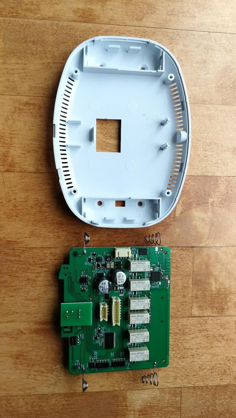
XEYWX-DB
Feb 17, 2021Thermostat
Equipment Class
DSS - Part 15 Spread Spectrum Transmitter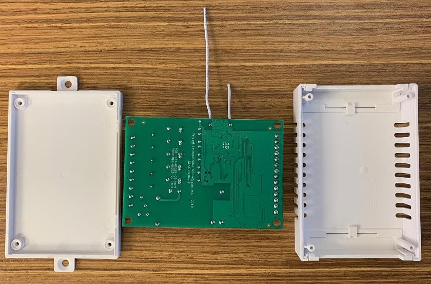
XEY-ZX-HV
Jan 27, 2021High Voltage Thermostat
Equipment Class
DTS - Digital Transmission System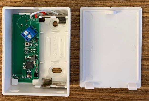
XEY-ZX-DS
May 10, 2020ZX Door Switch
Equipment Class
DSS - Part 15 Spread Spectrum Transmitter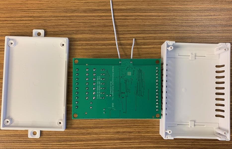
XEY-ZX-LV
May 05, 2020Low Voltage Thermostat
Equipment Class
DSS - Part 15 Spread Spectrum Transmitter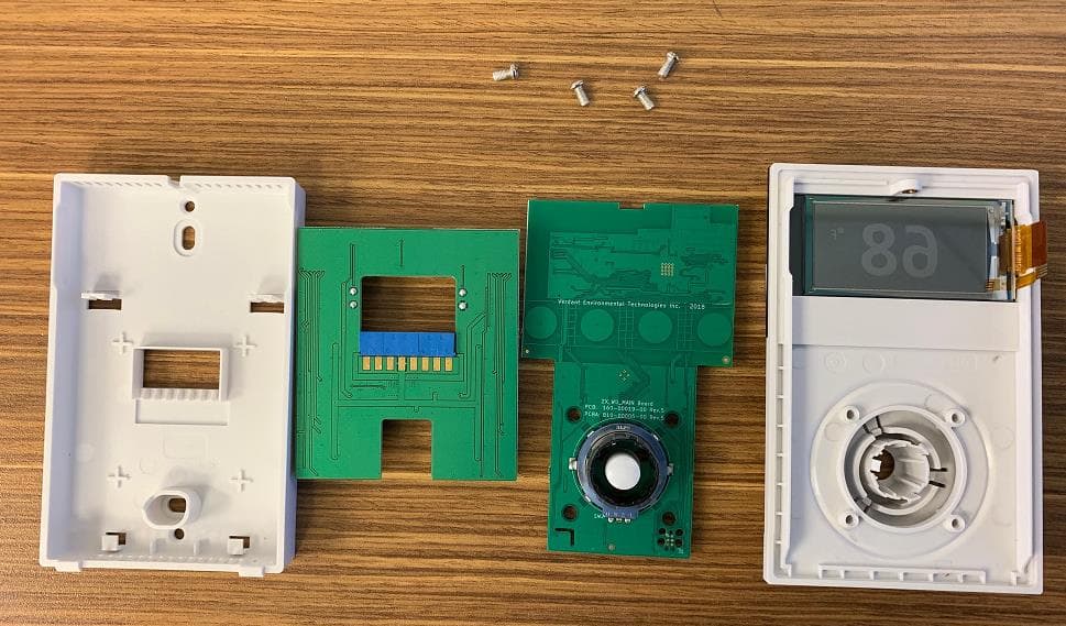
XEY-ZX-WU
Apr 30, 2020ZX Wired Thermostat
Equipment Class
DTS - Digital Transmission System