XJLTMS9250FCCTMS9250
Honeywell Sensing and Control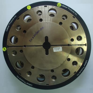
Click to zoom
Application Details
- Equipment Class
- DXX - Part 15 Low Power Communication Device Transmitter
- Date of Grant
- May 16, 2011
- Application Purpose
- Original Equipment
- Date of Application
- May 16, 2011
- Equipment Note
- TMS9250
- Frequency Range
- 13.55300000 - 13.56700000
- Country
- United Kingdom
Documents & Files
Document Text
Text extracted from the exhibit documents filed with the FCC. Open a document above to read the original.
Users Manual
TMS 9250 Product User Manual V 1.0 May 2011 Release V 1.0 Honeywell Confidential & Proprietary This work contains valuable, confidential and proprietary information. Disclosure, use or reproduction outside of Honeywell International Inc. is prohibited except as authorized in writing. This unpublished work is protected by the laws of the United States and other countries. V 1.0 TMS 9250 Product User Manual iii May 2011 Honeywell Confidential & Proprietary About This Document Release Information Document Name Document ID Release Number Publication Date TMS 9250 Product User Manual V 1.0 May 2011 V 1.0 TMS 9250 Product User Manual v May 2011 Honeywell Confidential & Proprietary Symbol Definitions The following table lists those symbols used in this document to denote certain conditions. Symbol Definition ATTENTION: Identifies information that requires special consideration. TIP: Identifies advice or hints for the user, often in terms of performing a task. REFERENCE -EXTERNAL: Identifies an additional source of information outside of the bookset. REFERENCE - INTERNAL: Identifies an additional source of information within the bookset. CAUTION Indicates a situation which, if not avoided, may result in equipment or work (data) on the system being damaged or lost, or may result in the inability to properly operate the process. CAUTION: Indicates a potentially hazardous situation which, if not avoided, may result in minor or moderate injury. It may also be used to alert against unsafe practices. CAUTION symbol on the equipment refers the user to the product manual for additional information. The symbol appears next to required information in the manual. WARNING: Indicates a potentially hazardous situation, which, if not avoided, could result in serious injury or death. WARNING symbol on the equipment refers the user to the product manual for additional information. The symbol appears next to required information in the manual. WARNING, Risk of electrical shock: Potential shock hazard where HAZARDOUS LIVE voltages greater than 30 Vrms, 42.4 Vpeak, or 60 VDC may be accessible. vi TMS 9250 Product User Manual V 1.0 Honeywell Confidential & Proprietary May 2011 Symbol Definition ESD HAZARD: Danger of an electro-static discharge to which equipment may be sensitive. Observe precautions for handling electrostatic sensitive devices. Protective Earth (PE) terminal: Provided for connection of the protective earth (green or green/yellow) supply system conductor. Functional earth terminal: Used for non-safety purposes such as noise immunity improvement. NOTE: This connection shall be bonded to Protective Earth at the source of supply in accordance with national local electrical code requirements. Earth Ground: Functional earth connection. NOTE: This connection shall be bonded to Protective Earth at the source of supply in accordance with national and local electrical code requirements. Chassis Ground: Identifies a connection to the chassis or frame of the equipment shall be bonded to Protective Earth at the source of supply in accordance with national and local electrical code requirements. V 1.0 TMS 9250 Product User Manual vii May 2011 Honeywell Confidential & Proprietary V 1.0 TMS 9250 Product User Manual ix May 2011 Honeywell Confidential & Proprietary Contents 1. TMS 9250 TORQUE MEASUREMENT SYSTEM ........................11 1.1 Important safety and certification information .......................................... 11 1.2 In The Box ...................................................................................................... 13 1.3 Intended Use .................................................................................................. 14 Torque Sensor .....................................................................................................................14 Principle of Telemetry ..........................................................................................................14 Usage scenario of TMS 9250...............................................................................................15 1.4 Installation and Setup ................................................................................... 15 2. MODES OF OPERATION ............................................................18 2.1 Normal mode operation detailed description............................................. 18 Normal mode operation........................................................................................................18 2.2 Fast mode operation detailed description.................................................. 21 Fast hmode operation ..........................................................................................................21 2.3 Analog Output characteristics ..................................................................... 24 3. CALIBRATION .............................................................................25 3.1 System Calibration Method .......................................................................... 25 3.2 Shunt Calibration .......................................................................................... 26 3.3 Storage and Recalibration............................................................................ 27 4. TROUBLESHOOTING .................................................................28 4.1 “Power On” light is not showing ................................................................. 28 4.2 “Rotor Active” light is not showing ............................................................ 28 4.3 Shunt calibra-tion does not operate............................................................ 28 4.4 Cannot communicate....................................................................................29 5. PRODUCT SPECIFICATIONS .....................................................31 Contents x TMS 9250 Product User Manual V 1.0 Honeywell Confidential & Proprietary May 2011 6. APPENDICES ......................…
Text truncated - open the document above for the full version.
External Photos
Honeywell Page 1 of 20 External Photo Rotor CCM Note: Naming on insulated labels is subjected to change. Honeywell Page 2 of 20 RF cable SPM Note : 1. Analog output cables are not supplied. Only RS 232 is supplied 2. New label with FCC, CE and statement will be pasted after certification. Honeywell Page 3 of 20 Power adapter CCM Setting gauge
ID Label/Location Info
FO-55112-C 4 HONEYWELL PART NUMBER SIZE DRAWING NAME SHEET C TITLE SCALE DRAWN CHECK Pro/ENGINEER REV THIS DRAWING COVERS A PROPRIETARY ITEM AND IS THE PROPERTY OF HONEYWELL. THIS DRAWING IS NOT TO BE COPIED OR USED WITHOUT THE PERMISSION OF HONEYWELL. TOLERANCES UNLESS NOTED: A 321 B C D 4321 A B C D TYPE CAGE_CODE 4.50 1.37 2.23 1.19 .47 .6 5.14 8.30 9.50 5.80 1.4 9.50 4X R.600 1.83 1.60 2.06 3.06 2.84 2.25 1.95 1.65 1.45 - REVDOCUMENTCHANGED BYCHECK A0075157MH 10MAR11VSY DESIGN UNITS: INCH INTERPRET PER ASME Y14.5M-1994 OTHER HONEYWELL ENGINEERING STANDARDS MAY APPLY 3D FRONT PANEL LABEL, SPM, TMS GEN-II MH11MAR11 VSY11MAR11 1 OF 1 1:1 E-014-0642-00A BLACK BACKGROUND NOTES: 1. MATERIAL: 0.007" THICK TEXTURED POLYESTER, ADHESIVE BACKING TYPE 3M-467MP, REVERSE PRINTED BLUE (PMS2728), GRAY (COOL GRAY 3) AND WHITE ON BLACK BACKGROUND. PEEL OFF PROTECTIVE FILM ON TOP FACE 2. NO ADHESIVE BACKING IN LIGHT GRAY AREA 3. "HONEYWELL" TO BE 'HELVETICA' .50 TALL, COLOR: PANTONE 485C, RED. 4. "FCC ID:APPROVAL PENDING" TO BE ARIAL (BOLD) .14 TALL, COLOR: WHITE 5. FCC STATEMENT TO BE ARIAL(BOLD) .1 TALL, COLOR: WHITE 6. PART MUST BE FREE OF BURRS AND SHARP EDGES. 7. "CE" AND "FC" TO BE .39 TALL, AND COMPLY TO CE MARKING STANDARDS, COLOR: WHITE. 8. PRODUCT IS UNDER CERTIFICATION TESTING FOR FCC AND CE. LABEL WILL BE RELEASED AFTER COMPLIANCE TO STANDARDS This device complies with Part 15 of the FCC rules. Operation is subject to the following two conditions: (1) This device may not cause harmful interference, and (2) This device must accept any interference received, including interference that may cause undesired operation. LIGHT GRAY BACKGROUND .20 DIFFUSED WINDOW (3) PLACES AS SHOWN .31 EMBOSSED BLACK BUTTON
Internal Photos
Honeywell Page 4 of 20 Internal Photos Rotor Electronics RTE stack up RTE filter – main bare board top side RTE filter – main bare board bottom side Honeywell Page 5 of 20 RTE filter – main assembled top side RTE filter- main assembled bottom side Rotor Antenna Rotor Antenna Honeywell Page 6 of 20 Rotor Element top side Rotor Element side view Rotor Element covers Honeywell Page 7 of 20 RF cable Co-axial connector Tri-axial connector Core Honeywell Page 8 of 20 CCM CCM Casing CCM PCB Note: Label naming are subjected to change Honeywell Page 9 of 20 CCM Spacer Honeywell Page 10 of 20 SPM SPM Top label Note: New label with FCC, CE and statement will be pasted after certification. SPM LID ITO film Honeywell Page 11 of 20 SPM LID SPM LID back side Honeywell Page 12 of 20 SPM LID conductiv e gasket SPM LID to casing earth wire SPM LED PCB top and bottom bare and assemble d boards Honeywell Page 13 of 20 SPM Inside SPM Sides Honeywell Page 14 of 20 SPM IO cables SPM IO BOX SPM IO LID, feed thru’s and BOX Honeywell Page 15 of 20 SPM IO PCB bare and assemble d SPM RF Bare PCB Honeywell Page 16 of 20 SPM RF assemble d boards Honeywell Page 17 of 20 SPM Digital Board bare and assemble d Honeywell Page 18 of 20 SPM FR4 SPM LED cable SPM RF coaxial cable, core and RF tri- axial connector IO glands Honeywell Page 19 of 20 SPM Power cable SPM RS232 Communi cation cable Honeywell Page 20 of 20 Power supply Power adapter Core Plug in socket
Test Report
Sensing & Control – Test & Measurement 11 th Apr 2011 TMS Gen II FCC certification testing – Worst case mo del identification Gautham Ramamurthy/ Vishal Malhan Vijay Talikoti/ Rajagopalan Narasimhan • TMS9000 is a torque measurement sensor that works on the principle of wireless telemetry. • This type of device is classified as intentional radiators. The intentional radiation (carrier) in this case is at 13.56MHz. • As per FCC rules, intentional radiators have to comply with FCC part15C. • Sec 15.207 Conducted emissions (150KHz to 30MHz) • Sec 15.209 Radiated emissions (1.705MHz to 30MHz & 30MHz to 1GHz) • Sec 15.223 or 15.225 Fundamental emissions (1.705MHz to 10MHz & 13.110MHz to 14.010MHz respectively.) Introduction: 2 HONEYWELL - CONFIDENTIAL File Number • For certification testing the worst case model would be tested in a FCC listed Lab and the results would be submitted to Elite (TCB) for certification. • Based on the test results of the worst case model and the following justification (combination of theoretical & test results) Honeywell te am requests certification for all the models/variants having smaller antenna size th an the worst case model (largest antenna size). • This document establishes that 1. 225 size rotor is the worst case model. 2. The change in coupling style can be considered as a class 1 permissive change. Block Diagram of TMS9000 Gen II Torque Sensor: 3 HONEYWELL - CONFIDENTIAL File Number Theory of Operation/Technical Description:• Honeywell Torque Sensors are designed structures th at perform in a predictable and repeatable manner when a torque is applied. This torque is tra nslated into a signal voltage by the resistance change of strain gages, which are attached to the t orque sensor structure. The change in resistance indicates the degree of deformation, and in turn, t he torque on the structure. • The strain gages are connected in a 4 arm Wheatston e bridge configuration which acts as an adding and subtracting electrical network and allows compe nsation for temperature effects as well as cancellation of signals caused by extraneous loadin g. • When the torque sensor is rotating, a means must be provided to transfer an excitation voltage to the rotational element from a stationary surface, a nd also to transfer the torque signal from the rotational element back to the stationary surface. This is accomplished through the use of digital telemetry. • The digital telemetry system consists of a receiver -transmitter module, a caliper-style coupling 4 HONEYWELL - CONFIDENTIAL File Number module (CCM) and a signal processing module (SPM). The receiver-transmitter module is an integral part of the torque sensor and is connected to the s train gauges and to the annular printed circuit board that contains the rotating antenna system. Wi thin the receiver-transmitter module, the sensor signals are amplified, digitized, and are then used to modulate the radio frequency carrier wave that is detected by the antenna after being transmitted across the air gap by the caliper coupling module. That same carrier wave is rectified to provide powe r to drive the strain gauges and the electronic components in the module, which is managed by a min iature microprocessor. • The caliper coupling module connects to the signal processing module via a simple tri-axial cable. The detector circuitry in the signal processing mod ule recovers the digital measurement data from the torque sensor and passes it to the second micro processor for scaling and linearizing. • The third microprocessor provides the drive to the two analog outputs, as well as the standard digital interfaces and the optional digital interfa ce modules. Extensive facilities are provided in software for setup and configuration of the complet e system. TMS9000 Coupling style and Torque measurement range s: • There are 3 coupling styles offered by Honeywell fo r the TMS Gen II product line • Flange to Flange • Integral Coupling • Shaft to Shaft • Each coupling style can have up to 6 rotor sizes (6 5, 90, 120, 150, 180 & 225). • 65 size is the smallest rotor size and 225 size is the largest rotor size. 5 HONEYWELL - CONFIDENTIAL File Number • 65 size is the smallest rotor size and 225 size is the largest rotor size. • The electronics (SPM, RTE & power supply) used in a ll the coupling styles/rotor sizes is the same.• The only variable between the rotor size is the dia meter of the sensing element on which the strain gage is mounted, Rotor antenna and the caliper coupling module.• 65 size has the smallest element, rotor antenna and CCM size. • 225 size has the largest element, rotor antenna and CCM size. • The following 3 slides show the setup of the 3 coup ling styles. 94000 Gen II Setup (Coupling Style: Flange to Flang e) CCM SPM Rotor Electronics (RTE) Caliper Coupling Module (CCM) Rotor element + Rotor antenna Signal Processing Module (SPM) Cable ferrite RTE Antenna 6 HONEYWELL - CONFIDENTIAL File Number Plug in Adaptor PS RF Cable Power supply adaptor & cable ferrite Cable ferrite CCM SPM Caliper Coupling Module (CCM) Rotor element + RTE antenna Signal Processing Module (SPM) Mechanical Coupling style is changed Rotor Electronics (RTE) Rotor Antenna Cable ferrite 94000 Gen II Setup (Coupling Style: Integral Coupli ng) 7 HONEYWELL - CONFIDENTIAL File Number PS RF Cable Power supply adaptor & cable ferrite Cable ferrite No Change in electronics. Only rotor mechanical coupling is changed. Plug in Adaptor 94000 Gen II Setup (Coupling Style: Shaft to Shaft) CCM SPM Signal Processing Module (SPM) Mechanical Coupling style is changed Rotor Electronics (RTE) Rotor Antenna Cable ferrite 8 HONEYWELL - CONFIDENTIAL File Number PS RF Cable Power supply adaptor & cable ferrite Cable ferrite Plug in Adaptor No Change in electronics. Only rotor mechanical coupling is changed. TMS9000 Gen II Connection diagram 9 HONEYWELL - CONFIDENTIAL File Number Radiated emission test summary: 1MHz-30MHz Test Setup photos: Limits: Summary: 10 HONEY…
Text truncated - open the document above for the full version.
Test Report
FCC CERTIFICATION TEST REPORT FOR TMS 9250 Manufactured by M/s. Honeywell International, Columbus, US Report Reference Number: EMC_tst_0527-1 Rev A Equipment Under Test (EUT): TMS 9250 Sample Identification: Production sample Model Number of EUT : TMS 92516 Serial Number of EUT : 1182664 Power Supply Model : EA1020B1-12-6E-Rev A Serial Number of Power Supply : 13121020131C3 Software Version : 1.40 Hardware Version : Revision A Number of Samples: 1 Manufacturer name: M/s. Honeywell International, Columbus, USA Address: Honeywell International, 2080 Arlingate Lane, Columbus, OH 43228, USA Testing Laboratory: M/s. Honeywell Technology Solutions Lab, Bangalore Address: #19/2, Deverabisanahalli Village, K R Puram Hobli, Bangalore – 560 103, INDIA Test Dates: 25-27, April, 2011 Applicable Tests: 1. Radiated Emission of Carrier Frequency, FCC § 15.225(a) 2. Radiated Spurious Emission, FCC § 15.225(d) 3. Frequency Stability, FCC § 15.225(e) 4. Conducted Emission on AC power lines, FCC § 15.207(a) Test Results: One sample was tested as per above applicable standard and the sample meets the test specifications. Prepared By: Approved By: Name: Bhanuprakash M Venkatesh Name: L Narasimha Charyulu Signature : Signature: Date : 28-APRIL-2011 Date: 28-APRIL-2011 This Test Report relates to the above mentioned test sample only. Without the permission of the test center this report is not permitted to be duplicated in extracts. This report is not entitled to carry any safety mark on this or similar products. Test Report No. EMC_tst_0527-1 Page 2 of 28 Test Summary 1. Radiated Emission of Carrier Frequency Result: PASS 2. Spurious Radiated Emission Result: PASS 3. Frequency Stability Result: PASS 4. Conducted Emission Test on AC power line Result: PASS Test Report No. EMC_tst_0527-1 Page 3 of 28 Acronyms and Abbreviations Table 1 : Acronyms and Abbreviations Acronyms Abbreviations μV Micro Volt AC Alternating Current AVG Average CCM Caliper style Coupling Module CPU Central Processing Unit dB Decibel EUT Equipment Under Test FCC Federal Communications Commission I/O Input / Output kHz Kilo Hertz m meter MHz Mega Hertz Mod and De-Mod Modulation and De-Modulation PS Power Supply QP Quasi Peak RF Radio Frequency RTE Rotor Electronics SPM Signal Processing Module TMS Torque Measurement System Test Report No. EMC_tst_0527-1 Page 4 of 28 Table of Contents TEST SUMMARY ............................................................................................................................................................ 2 ACRONYMS AND ABBREVIATIONS ............................................................................................................................... 3 1. PRODUCT INFORMATION ..................................................................................................................................... 5 2. RADIATED EMISSION OF CARRIER FREQUENCY TEST .......................................................................................... 7 3. RADIATED SPURIOUS EMISSION TEST .................................................................................................................. 9 4. FREQUENCY STABILITY TEST ............................................................................................................................... 12 5. CONDUCTED EMISSION TEST .............................................................................................................................. 15 6. APPENDIX-1: EMISSION PLOTS AND FREQUENCY MEASUREMENTS................................................................. 18 7. APPENDIX-2: TEST SETUP PHOTOS ..................................................................................................................... 24 List of Figures Figure 1 : Block Diagram of the EUT (TMS 9250) ....................................................................................................... 5 Figure 2 : Block Diagram of Frequency Stability Test Setup ...................................................................................... 13 Figure 3 : Radiated Emission of carrier frequency, Horizontal Polarization ............................................................... 18 Figure 4 : Radiated Emission of carrier frequency, Vertical Polarization ................................................................... 18 Figure 5 : Radiated Spurious Emission: 150 kHz - 30 MHz: Vertical Polarization.................................................... 19 Figure 6 : Radiated Spurious Emission: 150 KHz - 30 MHz: Horizontal Polarization ............................................... 19 Figure 7 : Radiated Spurious Emission: 30 MHz - 1 GHz: Vertical Polarization........................................................ 20 Figure 8 : Radiated Spurious Emission: 30 MHz - 1 GHz: Horizontal Polarization ................................................... 20 Figure 9 : Conducted Emission on Line (With Permanent Antenna) .......................................................................... 22 Figure 10 : Conducted Emission on Neutral (With Permanent Antenna) .................................................................... 22 Figure 11 : Conducted Emission on Line (Dummy Load)........................................................................................... 23 Figure 12 : Conducted Emission on Neutral (Dummy Load) ...................................................................................... 23 Figure 13 : General EUT Test Setup Diagram............................................................................................................. 24 Figure 14 : Loop Antenna, Horizontal Polarization (150 kHz - 30 MHz) ................................................................... 24 Figure 15 : Loop Antenna, Vertical Polarization (150 kHz - 30 MHz) ....................................................................... 25 Figure 16 : Bi-log Antenna, Horizontal Polarization (30 MHz - 1 GHz) ...................................…
Text truncated - open the document above for the full version.
Test Setup Photos
Test Report No. EMC_tst_0527-1 Page 24 of 28 7. Appendix-2: Test Setup Photos Figure 13 : General EUT Test Setup Diagram Figure 14 : Loop Antenna, Horizontal Polarization (150 kHz - 30 MHz) Test Report No. EMC_tst_0527-1 Page 25 of 28 Figure 15 : Loop Antenna, Vertical Polarization (150 kHz - 30 MHz) Figure 16 : Bi-log Antenna, Horizontal Polarization (30 MHz - 1 GHz) Test Report No. EMC_tst_0527-1 Page 26 of 28 Figure 17 : Bi-log Antenna, Vertical Polarization (30 MHz - 1 GHz) Figure 18 : Frequency Stability Test Setup (Inside Thermal Chamber) Test Report No. EMC_tst_0527-1 Page 27 of 28 Figure 19 : Frequency Stability Test Setup Figure 20 : Conducted Emission Test Setup with permanent Antenna Test Report No. EMC_tst_0527-1 Page 28 of 28 Figure 21 : Conducted Emission Test Setup with dummy load Figure 22 : Dummy Load - Internal View
Contact Information
Applicant
Stephen Ross Borthwick(Approval Engineer)
Technical Contact
Non-Technical Contact
HoneywellMichael Mack
michael.mack@honeywell6148507832
Test Firm
Honeywell Technology Solutions Lab Pvt. LtdMr. Prasanna Kumar BudalTaranath
Technical Specifications
| # | Rule Parts | Frequency Range | Power Output |
|---|---|---|---|
| 1 | 15C | 13.553 MHz - 13.567 MHz | - |
Other Applications from Honeywell Sensing and Control
XJLWPS001
Jul 29, 2014WPS001
Equipment Class
DTS - Digital Transmission System
XJLTMS9000FCC
Jan 06, 2010TMS9000
Equipment Class
DXX - Part 15 Low Power Communication Device Transmitter