XJN-IPC019IP Camera
SHUOYING INDUSTRIAL (SHENZHEN) CO., LTD.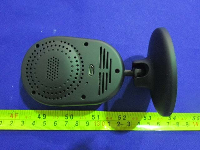
Click to zoom
Application Details
- Equipment Class
- DTS - Digital Transmission System
- Date of Grant
- Sep 07, 2015
- Application Purpose
- Original Equipment
- Date of Application
- Sep 07, 2015
- Equipment Note
- IP Camera
- Frequency Range
- 2422.00000000 - 2452.00000000
- Country
- China
Documents & Files
Document Text
Text extracted from the exhibit documents filed with the FCC. Open a document above to read the original.
Users Manual
Quick guide For Connection on Android Devices Download APP Please Download and install the APP GuardPro before setting the IP Camera . Search “Guardpro” on Google play store or scan the QR Code below to quickly get it The following steps will guide you to complete the IP Camera connection. Click the icon to launch the APP。 Connect the power supply with the IP Camera,then the bluelight will be on, after 2 secondsthe red lightis always on. And 15 seconds later the red light will be off,then the IPCamera detection by itself. For first time to use Guardpro, Click the icon “Click to add new camera”. And thenclick “Setup Camera”, if the bluelight is blinking, Android you can click “Yes”, Else you need click “No”,follow the prompts to reset the IPCamera. Insert a pin into the reset button on the back of the camera, press down and hold for 5 seconds. Wait for the camera to reset and the blue light to blink. Click the Guardpro icon to back to previous. Then click “Yes”. Enter the Wi‐Fi name and password, then click “Next”. If WiFi without password,you can click “Next”. About 15 seconds later,the blue light of the IP Camera will be off, after another 5 seconds, the blue light will be always on. Then the IP Camera is already on line. You will see User and camerainformations. The default Username is “admin”;The default Password is “admin”;The default Camera Name is “Camera”. Click the “Camera” icon, you can rename the Camera Name. Click add icon,you will back to main screen. Now please click the preview icon to enjoy the real‐time monitoring. Click Settings,you will see this menu. Select “Edit the Camera” to open Settings page. Hereyou will see “Camera ID:”,”Username:”,”Password:”,”Camera Name:” , and advanced settings icon. “Reconnect” icon will Refresh the IP Camera State . ”Remove the camera” to remove this IP Camera. For protect your privacy, you need to change the password .click “settings” icon, and click “Modify Security password” icon, Input the Old key “admin” and input New key, Confirm New Key. you can change the password Settings: Here you can open settings. snapshot: The pictures will be saved in your Mobile phone,you can click video icon ,select "Local Album" to review these pictures Video record: The Video records will be saved in your Mobile phone,you can click video icon ,chose "Local Album" to review these records. voice: When the icon is gray, you can hear from the IP Camera。When the icon is blue, you can talk to the IP Camera。 Video view: You can select local album to watch vedios and pictures on your mobile phone. Or you can select device event to watch vedios on IPcamera. Definition Standard Definition 640*360 Hi gher definition1280*720 successful. “Advanced Settings” you can also change ”Motion Detection settings” , “Volume Settings” , “Recording Settings” , “Timezone settings”, and Update Firmware , check device information etc. If you can not see the video , you need to click “reconnect” icon,toRefresh the IP Camera State . When you set the motion detection on , you will get the message when the IP Camera detectedsomething wrong . You can close it , or view events if the IP Camera with the MicrSD in it. Quick guide For Connection on IOS Devices Download APP Please download and install the APP Guardpro before setting the IP Camera. Search “Guardpro” on APP store or scan the QR Code below to quickly get it. The following steps will guide you to complete the IP Camera connection. IOS Connect the power supply with the IP Camera,then the bluelight will be on, after 2 secondsthe red lightis always on. And 15 seconds later the red light will be off,then the IPCamera detection by itself. For first time to use Guardpro, Click the icon “+”. And thenclick “Setup Camera”, if the bluelight is blinking, you can click “Yes”, Else you need click “No”,follow the prompts to reset the IPCamera. Insert a pin into the reset button on the back of the camera, press down and hold for 5 seconds. Wait for the camera to reset and the blue light to blink. Click the Guardpro icon to back to previous. Then click “Yes”. Enter the Wi‐Fi name and password, then click “Next”. If WiFi without password,you can click “Next”. About 15 seconds later, the blue light of the IP Camera will be off, after another 5 seconds, the blue light will be always on. Then the IP Camera is already on line. You will see User and cameraInformations. The default Username is “admin”, The default Password is “admin”. The default Camera Name is “Camera”. Click “Finish” icon,you will back to APP Main screen. Now please click the preview icon to enjoy the real‐time monitoring. Click “Setting” icon,you can see “Basic info”. Click “Share Camera QRCode”, you can get the QRCode of this IP Camera. You can share your IP Camera to others by the QRCode. Setting: Here you can open settings. snapshot: The pictures will be saved in your Mobile phone,you can click Photos icon on your Mobile phone to review Video record: The Video records will be saved in your Mobile phone,you can click Photos icon on your Mobile phone to review theserecords. voice: When the icon is gray, you can hear from the IP Camera。When the icon is blue, you can talk to the IP Camera。 Video view: You can see a list of videos on youIP camera. Definition Standard Definition 640*360 Hi gher definition1280*720 For protect your privacy, you need to change the password .click “basic settings” icon, input the Old Password “admin”, input New Password, and Confirm New Password. You can change the password successful. You also can modify the IP Camera Name here. In “Advanced Settings”, you can change “Mirror & Flip” , “Environment Mode” , ”Motion Detection” , “Alarm Mode” , “Record Mode” , “OSD” , “Timezone” , etc. Slide to left, you can remove the IP Camera here. Any Changes or modifications not expressly approved by the party responsible for compliance could void the user’s authority to operate the equipment. This device complies with part 15 of the FCC Rules. Operation is subject to th…
Text truncated - open the document above for the full version.
Cover Letter(s)
SHUOYING INDUSTRIAL (SHENZHEN) CO., LTD Add: Shuoying Road, Hebei Industry Area,Dalang, Longhua Town, Baoan, Shenzhen, China. Tel: 86-755-29809865 Fax: 0755-28177333 DECLARATION OF SIMILARITY Date: 2015-7-31 We, SHUOYING INDUSTRIAL (SHENZHEN) CO., LTD, hereby declare that product: IPCamera, model: IPC020 are electrically identical with the model: IPC019 which was tested by BACL with the same electromagnetic emissions and electromagnetic compatibility characteristics. A description of the difference between the two models and those that are declared similar are as follows: They are the same product, and have the different model name and shell, please check the photos in the test report for reference, they also have different length of antenna, but the antenna FPC parameters are the same. Please contact me should there be need for any additional clarification or information. Best Regards, Signature Tony Pan President
External Photos
EXHIBIT B - EUT EXTERNAL PHOTOGRAPHS Test Model: IPC019 EUT – Top View EUT – Bottom View EUT – Front View EUT – Back View EUT – Side View EUT – Side View Test Model: IPC020 EUT – Top View EUT – Bottom View EUT – Front View EUT – Back View EUT – Side View EUT – Side View
ID Label/Location Info
EXHIBIT A - FCC ID LABELING AND LOCATION FCC ID Label Proposed FCC ID Label Location The label shown shall be permanently affixed at a conspicuous location on the device and be readily visible to the user at the time purchase (Labeling requirements per 2.925) Label Here
Internal Photos
EXHIBIT C - EUT INTERNAL PHOTOGRAPHS Test Model: IPC019 EUT – Uncover View EUT – Uncover View EUT – Uncover View EUT – Uncover View EUT – LED Board Top View EUT –LED Board Bottom View EUT – Main Board Top View EUT – Main Board Bottom View EUT –Camera View EUT –RF Chip View EUT –Antenna View Test Model: IPC020 EUT – Uncover View EUT – Uncover View EUT – Uncover View EUT – Uncover View EUT – LED Board Top View EUT –LED Board Bottom View EUT – Main Board Top View EUT – Main Board Bottom View EUT –Camera View EUT –RF Chip View EUT –Antenna View
RF Exposure Info
Bay Area Compliance Laboratories Corp. (Dongguan) Report No.: RDG150721001-00A FCC Part 15.247 Page 10 of 53 FCC §15.247 (i) & §1.1307 & §2.1091- MAXIMUM PERMISSIBLE EXPOSURE (MPE) Applicable Standard According to subpart 15.247(i) and subpart §1.1307, systems operating under the provisions of this section shall be operated in a manner that ensures that the public is not exposed to radio frequency energy level in excess of the Commission’s guidelines. Limits for Maximum Permissible Exposure (MPE) (§1.1310, §2.1091) (B) Limits for General Population/Uncontrolled Exposure Frequency Range (MHz) Electric Field Strength (V/m) Magnetic Field Strength (A/m) Power Density (mW/cm 2 ) Averaging Time (minutes) 0.3–1.34 614 1.63 *(100) 30 1.34–30 824/f 2.19/f *(180/f²) 30 30–300 27.5 0.073 0.2 30 300–1500 / / f/1500 30 1500–100,000 / / 1.0 30 f = frequency in MHz; * = Plane-wave equivalent power density; According to §1.1310 and §2.1091 RF exposure is calculated. Calculated Formulary: Predication of MPE limit at a given distance S = PG/4πR² = power density (in appropriate units, e.g. mW/cm 2 ); P = power input to the antenna (in appropriate units, e.g., mW); G = power gain of the antenna in the direction of interest relative to an isotropic radiator, the power gain factor, is normally numeric gain; R = distance to the center of radiation of the antenna (appropriate units, e.g., cm); Calculated Data: Frequency Range (MHz) Antenna Gain Conducted Power Evaluation Distance (cm) Power Density (mW/cm 2 ) MPE Limit (mW/cm 2 ) (dBi) (numeric)(dBm)(mW) 2412-2462 2 1.58 20.81120.520 0.038 1.0 2422-2452 2 1.58 21.15130.320 0.041 1.0 Result: The device meet FCC MPE at 20 cm distance.
Test Report
Note: This test report is prepared for the customer shown above and for the device described herein. It may not be duplicated or used in part without prior written consent from Bay Area Compliance Laboratories Corp. (Dongguan). This report is valid only with a valid digital signature. The digital signature may be available only under the Adobe software above version 7.0. FCC PART 15.247 TEST REPORT For SHUOYING INDUSTRIAL (SHENZHEN) CO., LTD. No.1,Longgang Road, Buji, Longgang, Shenzhen City, Guangdong Province, P.R. China FCC ID: XJN-IPC019 Report Type: Original Report Product Type: IP Camera Test En gineer: Lion Xiao Re port Number: RDG150721001-00A Re port Date: 2015-08-12 Reviewed By: Sula Huang RF Leader Test Laboratory: Bay Area Compliance Laboratories Corp. (Dongguan) No.69 Pulongcun, Puxinhu Industrial Zone, Tangxia, Dongguan, Guangdong, China Tel: +86-769-86858888 Fax: +86-769-86858891 www.baclcorp.com.cn Bay Area Compliance Laboratories Corp. (Dongguan) Report No.: RDG150721001-00A FCC Part 15.247 Page 2 of 53 TABLE OF CONTENTS GENERAL INFORMATION ....................................................................................................................................... 4 PRODUCT DESCRIPTION FOR EQUIPMENT UNDER TEST (EUT) ..................................................................................... 4 OBJECTIVE ................................................................................................................................................................... 4 RELATED SUBMITTAL(S)/GRANT(S) ............................................................................................................................. 4 TEST METHODOLOGY .................................................................................................................................................. 4 TEST FACILITY ............................................................................................................................................................. 5 SYSTEM TEST CONFIGURATION .......................................................................................................................... 6 DESCRIPTION OF TEST CONFIGURATION ...................................................................................................................... 6 EQUIPMENT MODIFICATIONS ....................................................................................................................................... 6 EUT EXERCISE SOFTWARE .......................................................................................................................................... 7 SUPPORT EQUIPMENT LIST AND DETAILS .................................................................................................................... 7 EXTERNAL CABLE ........................................................................................................................................................ 7 BLOCK DIAGRAM OF TEST SETUP ................................................................................................................................ 8 SUMMARY OF TEST RESULTS ............................................................................................................................... 9 FCC §15.247 (i) & §1.1307 & §2.1091- MAXIMUM PERMISSIBLE EXPOSURE (MPE) ....................................... 10 APPLICABLE STANDARD ............................................................................................................................................ 10 FCC §15.203 - ANTENNA REQUIREMENT ........................................................................................................... 11 APPLICABLE STANDARD ............................................................................................................................................ 11 ANTENNA CONNECTOR CONSTRUCTION .................................................................................................................... 11 FCC §15.207 (a) – AC LINE CONDUCTED EMISSIONS ..................................................................................... 12 APPLICABLE STANDARD ............................................................................................................................................ 12 MEASUREMENT UNCERTAINTY .................................................................................................................................. 12 EUT SETUP ................................................................................................................................................................ 12 EMI TEST RECEIVER SETUP ....................................................................................................................................... 13 TEST PROCEDURE ...................................................................................................................................................... 13 CORRECTED AMPLITUDE & MARGIN CALCULATION ................................................................................................. 13 TEST EQUIPMENT LIST AND DETAILS ......................................................................................................................... 14 TEST RESULTS SUMMARY .......................................................................................................................................... 14 TEST DATA ................................................................................................................................................................ 14 FCC §15.209, §15.205 & §15.247(d) - SPURIOUS EMISSIONS ............................................................................. 17 APPLICABLE STANDARD ............................................................................................................................................ 17 MEASUREMENT UNCERTAINTY .............................................…
Text truncated - open the document above for the full version.
Test Setup Photos
EXHIBIT D - TEST SETUP PHOTOGRAPHS Conducted Emissions - Front View Conducted Emissions – Side View Radiated Emission - Front View (Below 1GHz) Radiated Emission - Rear View (Below 1GHz) Radiated Emission - Front View (Above 1GHz) Radiated Emission - Rear View (Above 1GHz)
Contact Information
Applicant
Tony Pan
Test Firm
Bay Area Compliance Laboratories Corp. (Dongguan)John Chan
[email protected]86-769-86858888
Technical Specifications
| # | Rule Parts | Frequency Range | Power Output |
|---|---|---|---|
| 2 | 15C | 2.42 GHz - 2.45 GHz | 130.00 mW |
Other Applications from SHUOYING INDUSTRIAL (SHENZHEN) CO., LTD.
XJN-PA7062X
Dec 27, 2014Mobile Internet Devices
Equipment Class
JBP - Part 15 Class B Computing Device PeripheralXJN-PX4032
Sep 20, 2014Mobile internet device
Equipment Class
DTS - Digital Transmission System
XJN-PA7810X
Jun 26, 2014Mobile Internet Devices
Equipment Class
DSS - Part 15 Spread Spectrum Transmitter
XJN-PR7062X
May 06, 2014Mobile Internet Device
Equipment Class
DTS - Digital Transmission System
XJN-PA7807X
Feb 20, 2014Mobile Internet Device
Equipment Class
DTS - Digital Transmission System