XM5-SMG2N1Nano wiReach 2nd Generation 802.11b/g/n (BRD-SMG2N1)
Connect One Ltd.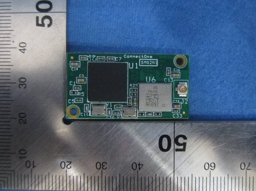
Click to zoom
Application Details
- Equipment Class
- DTS - Digital Transmission System
- Date of Grant
- Sep 05, 2014
- Application Purpose
- Original Equipment
- Date of Application
- Sep 05, 2014
- Equipment Note
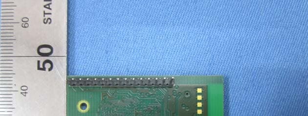
- Nano wiReach 2nd Generation 802.11b/g/n (BRD-SMG2N1)
- Frequency Range
- 2412.00000000 - 2462.00000000
- Company
- Connect One Ltd.
- Country
- Israel
Documents & Files
Document Text
Text extracted from the exhibit documents filed with the FCC. Open a document above to read the original.
Users Manual
Connect OneConfidential user manual August 2014 iChip OS Version i2128D810D34 MBCM Manufacturer’s Firmware for use in Certification Testing 560 S. Winchester Blvd.20 Atir Yeda Street Suite 5001 st floor San Jose, CA 95128Kfar Saba 44643 Israel Tel: +1 (408) 572-5675Tel: +972-9-766-0456 Fax: +1 (408) 572-5601Fax: +972-9-766-0461 www.connectone.com Confidential Not Approved for Distribution Connect OneConfidential user manual Table of Contents 1.INTRODUCTION TO FIRMWARE I2128D810D81 MBCM ..................................................... 3 2.UNPACKING INSTRUCTIONS ................................................................................................ 3 3.AT+I COMMANDS .................................................................................................................... 4 4.EXAMPLE 1: TEST TX FUNCTIONS ....................................................................................... 5 5.IN CASE OF FAILURE .............................................................................................................. 6 Confidential Not Approved for Distribution Connect OneConfidential user manual 1. Introduction to firmware i2128D810D81 MBCM This firmware is provided with the intention of assisting customers of Connect One in performing certification tests for WiFi systems. This firmware is not recommended for release with production units and does not support the full functionality of the production version i2128D810D34. The AT+i commands, which are described in this document, control a special test mode of Broadcom’s 43362 802.11 b/g/n chipset. 2. Unpacking Instructions 1. Connect the RS232 cable to the serial port on the DUT (Device Under Test) and to COM1 or COM2 serial port on a PC. 2. Connect the power supply to the DUT and turn ON the power switch. 3. Please run HyperTerminal program. To launch from Windows XP: Start -> Programs -> Accessories -> Communications. 4. Choose a name for the connection. Click OK to approve. 5. In the option: “Connect using”, choose COM1 or COM1 serial port on the PC which is connected to the DUT. Click OK to approve. 6. Choose the following port settings: Bits per second: 9600 Data bits: 8 Parity: None Stop bits: 1 Flow control: None Click OK to approve. 7. a. Type the command: AT+i b. Press Enter. c. Expect to see the letters “AT+i” as you type. This is an echo by the DUT. d. Expect to see the response code: “I/OK” verifying the device is working. Confidential Not Approved for Distribution Connect OneConfidential user manual 3. AT+i Commands TestAT+i Command parametersdescription Set RF channel MTCH=xx = [1-14]X= channel 1 - 14 Set TX rateMTTR=rr = 1 for 1 mbps, r = 2 for 2mbps, r =5 for 5.5 mbps, r = 11 for 11 mbps, r = 6 for 6 mbps, r = 9 for 9 mbps, r = 12 for 12 mbps, r = 16 for 18 mbps, r = 24 for 24 mbps, r = 36 for 36 mbps, r = 12 for 48 mbps, r = 54 for 54 mbps r= 100 for MCS0 r= 101 for MCS1 r= 102 for MCS2 r= 103 for MCS3 r= 104 for MCS4 r= 105 for MCS5 r= 106 for MCS6 r= 107 for MCS7 Set Power at Antenna MTRP=p p = power in dbm [10 - 15] TX Carrier Wave continuous mode MTCW=ee = 0 – disable this mode e = 1 – enable mode, Transmits only the carrier signal, continuously. To end the test: MTCW = 0. Confidential Not Approved for Distribution Connect OneConfidential user manual TX continuous mode MTCM=e e = 1 – enable mode, e = 0 – disable this mode SET Inter Packet Gap in us TTO=uS On uSEC (20-100) Packet length IATO=lLength (1000-2000) Reset ichipDOWN 4. Example 1: Test TX functions 1. Power up the iChip and the RF processor. 2. Set channel 1: AT+iMTCH=1 3. Set rate 1 Mbit/sec: AT+iMTTR=1 4. Set power 15dbm: AT+iMTRP=15 5. Set SET Inter Packet Gap 20us: AT+iTTO=20 6. Set Packet length 3000: AT+iiato=3000 7. Enable continuous transmit mode: AT+iMTCM=1 8. End test: Either Power-Off or send: AT+iDOWN Confidential Not Approved for Distribution Antennas: Air Wave (EA-79F); Tekfun C. (M04-SR); YC Communication (Q24-24W); Pulse (W1030). Maximum Gain all: 2dBi. Antenna Manufacture :Connect One’s Model No.iW-ANT2-BL: Antenna gain: 2dBi Connect OneConfidential user manual 5. In Case of Failure Please contact our technical support via email: [email protected] Alternatively, call the office in Israel: +972-9-766-0456 FCC Statement This device complies with part 15 of the FCC Rules. Operation is subject to the following two conditions: (1) This device may not cause harmful interference, and (2) this device must accept any interference received, including interference that may cause undesired operation. Changes or modifications not expressly approved by the party responsible for compliance could void the user's authority to operate the equipment. FCC Radiation Exposure Statement The modular can be installed or integrated in mobile or fix devices only. This modular cannot be installed in any portable device, for example, USB dongle like transmitters is forbidden. This modular complies with FCC RF radiation exposure limits set forth for an uncontrolled environment. This transmitter must not be co-located or operating in conjunction with any other antenna or transmitter. This modular must be installed and operated with a minimum distance of 20 cm between the radiator and user body. If the FCC identification number is not visible when the module is installed inside another device, then the outside of the device into which the module is installed must also display a label referring to the enclosed module. This exterior label can use wording such as the following: “Contains Transmitter Module FCC ID: when the module is installed inside another device, the user manual of this device must contain below warning statements; 1. This device complies with Part 15 of the FCC Rules. Operation is subject to the following two conditions: (1) This device may not cause harmful interference. (2) This device must accept any interference received, including interference that may cause undesired operation. 2. Changes or modifications not expressly a…
Text truncated - open the document above for the full version.
Cover Letter(s)
Connect One Ltd. 20 Atir Yeda Street, Kfar Saba 44643 Israel DATE :2014-8-29 Nemko Canada Inc 303 River Road Ottawa, Ontario, Canada K1V 1H2 Attn: Director of Certification Authority to Act as Agent On our behalf, I appoint Hank Yan of Global United Technology Services Co., Ltd. 2nd Floor, Block No.2, Laodong Industrial Zone, Xixiang Road Baoan District Shenzhen Guangdong (Name and address) to act as our agent in the preparation of this application for equipment certification. I certify that submitted documents properly describe the device or system for which equipment certification is sought. I also certify that each unit manufactured, imported or marketed, as defined in the Federal Communications Commission’s regulations will have affixed to it a label identical to that submitted for approval with this application. For instances where our authorized agent signs the application for certification on our behalf, I acknowledge that all responsibility for complying with the terms and conditions for certification, as specified by Nemko Canada Inc, still resides with Connect One Ltd. and 20 Atir Yeda Street, Kfar Saba 44643 Israel ( applicant name and address). Dated this / Day of 8/29/2014 / Agency agreement expiration date: 8/29/2015
Cover Letter(s)
Modular approval Declaration letter We, Connect One Ltd. apply limited modular approval for Product: Nano wiReach 2nd Generation 802.11b/g/n (BRD-SMG2N1) Model: iW-SMG2N1 FCC ID XM5-SMG2N1 According to KDB 996369 D01 Module Equip Auth Guide v01r04 and part 15.212 requirement: 1) The radio elements must have the radio frequency circuitry shielded. Physical components and tuning capacitor(s) may be located external to the shield, but must be on the module assembly; Answer: NO. 2) The module must have buffered modulation/data inputs to ensure that the device will comply with Part 15 requirements with any type of input signal; Answer: Yes. All inputs to the modules are buffered through logic or microprocessor inputs. 3) The modular transmitter must have its own power supply regulation. Answer: Yes. A low drop out regulator is used for modular power supply regulation. 4) The module must contain a permanently attached antenna, or contain a unique antenna connector, and be marketed and operated only with specific antenna(s), per Sections 15.203, 15.204(b), 15.204(c), 15.212(a), 2.929(b); Answer: Yes. Device is equipped with unique antenna with reversed connector. 5) The module must demonstrate compliance in a stand-alone configuration; Answer: Yes. Refer to test report. 6) The module must be labelled with its permanently affixed FCC ID label, or use an electronic display (See KDB Publication 784748 about labelling requirements); Answer: Yes. The modular has a permanent fixed label, and below statement was listed in the User Manual: The host device must be labelled to display the FCC ID of the module ‘Contains FCC ID: XM5-SMG2N1’ 7) The module must comply with all specific rules applicable to the transmitter including all the conditions provided in the integration instructions by the grantee; Answer; Yes. The module comply with all specific rules applicable to the transmitter including all the conditions provided in the integration instructions by the grantee, Refer to test report and user manual . 8) The module must comply with RF exposure requirements Answer: Yes. Transmitter meets MPE calculation of 47 CFR Part 1.1307. Refer to MPE Reports and Refer to modular installation manual. The modular comply with RF exposure requirement for mobile and fix use configuration, with the separation distance between the user and the device's radiating element must be greater than 20 cm.
ID Label/Location Info
Size: 1*0.7mm Model: iW-SMG2N1 FCC ID: XM5-SMG2N1 IC: 8516A-SMG2N1
ID Label/Location Info
Label location
RF Exposure Info
FCC ID:XM5-SMG2N1 RF Exposure Evaluation Limits The criteria listed in the following table shall be used to evaluate the environment impact of human exposure to radio frequency (RF) radiation as specified in 1.1307(b) Limits for Maximum Permissible Exposure (MPE) Frequency range (MHz) Electric field strength (V/m) Magnetic field strength (A/m) Power density (mW/cm 2 ) Averaging time (minutes) (A) Limits for Occupational/Controlled Exposures 0.3–3.0 614 1.63 *(100) 6 3.0–30 1842/f 4.89/f *(900/f 2 ) 6 30–300 61.4 0.163 1.0 6 300–1500 f/300 6 1500–100,000 5 6 (B) Limits for General Population/Uncontrolled Exposure 0.3–1.34 614 1.63 *(100) 30 1.34–30 824/f 2.19/f *(180/f 2 ) 30 30–300 27.5 0.073 0.2 30 300–1500 f/1500 30 1500–100,000 1.0 30 f = frequency in MHz Friis transmission formula: Pd = (Pout*G)/(4*pi*r 2 ) Where Pd = power density in mW/cm 2 , Pout = output power to antenna in mW; G = gain of antenna in linear scale, Pi = 3.1416; R = distance between observation point and center of the radiator in cm Pd id the limit of MPE, 1 mW/cm 2 . If we know the maximum gain of the antenna and the total power input to the antenna, through the calculation, we will know the distance r where the MPE limit is reached. Test Procedure Software provided by client enabled the EUT to transmit and receive data at lowest, middle and highest channel individually. Test Result of RF Exposure Evaluation The maximum rated power is 19dBm, so the RF Exposure Evaluation is below: Maximum power to antenna (dBm) Maximum power to antenna (mW) Antenna Gain (dBi) Power Density at R=20cm (mW/cm 2 ) Limit (mW/cm 2 ) Result 19.00 79.43 2 0.02505 1.0 PASS
Test Report
Global United Technology Services Co., Ltd. Report No.: GTSE14080140601 Authorized Signature: Robinson Lo Laboratory Manager This report details the results of the testing carried out on one sample. The results contained in this test report do not relate to other samples of the same product and does not permit the use of the GTS product certification mark. The manufacturer should ensure that all products in series production are in conformity with the product sample detailed in this report. This report may only be reproduced and distributed in full. If the product in this report is used in any configuration other than that detailed in the report, the manufacturer must ensure the new system complies with all relevant standards. Any mention of GTS or testing done by GTS in connection with, distribution or use of the product described in this report must be approved by GTS in writing. This document cannot be reproduced except in full, without prior written approval of the Company. Any unauthorized alteration, forgery or falsification of the content or appearance of this document is unlawful and offenders may be prosecuted to the fullest extent of the law. Unless otherwise stated the results shown in this test report refer only to the sample(s) tested and such sample(s) are retained for 90 days only. FCC Report Applicant: Connect One Ltd Address of Applicant: 20 Atir Yeda Street, Kfar Saba 44643 Israel Equipment Under Test (EUT) Product Name: Nano wiReach 2nd Generation 802.11b/g/n (BRD-SMG2N1) Model No.: iW-SMG2N1 FCC ID: XM5-SMG2N1 Applicable standards: FCC CFR Title 47 Part 15 Subpart C Section 15.247:2013 Date of sample receipt: August 26, 2014 Date of Test: August 27-28, 2014 Date of report issued: August 29, 2014 Test Result : PASS * * In the configuration tested, the EUT complied with the standards specified above. Report No.: GTSE14080140601 Global United Technology Services Co., Ltd. Project No.: GTSE140801406RF 2nd Floor, Block No.2, Laodong Industrial Zone, Xixiang Road Baoan District, Shenzhen, China 518102 Telephone: +86 (0) 755 2779 8480 Fax: +86 (0) 755 2779 8960 Page 2 of 51 2 Version Version No. Date Description 00 August 29, 2014 Original Prepared By: Date: August 29, 2014 Project Engineer Check By: Date: August 29, 2014 Reviewer Report No.: GTSE14080140601 Global United Technology Services Co., Ltd. Project No.: GTSE140801406RF 2nd Floor, Block No.2, Laodong Industrial Zone, Xixiang Road Baoan District, Shenzhen, China 518102 Telephone: +86 (0) 755 2779 8480 Fax: +86 (0) 755 2779 8960 Page 3 of 51 3 Contents Page 1 COVER PAGE ........................................................................................................................................... 1 2 VERSION .................................................................................................................................................. 2 3 CONTENTS .............................................................................................................................................. 3 4 TEST SUMMARY ..................................................................................................................................... 4 5 GENERAL INFORMATION ...................................................................................................................... 5 5.1 CLIENT INFORMATION ......................................................................................................................... 5 5.2 GENERAL DESCRIPTION OF EUT ......................................................................................................... 5 5.3 TEST MODE ........................................................................................................................................ 6 5.4 DESCRIPTION OF SUPPORT UNITS ....................................................................................................... 6 5.5 TEST FACILITY .................................................................................................................................... 7 5.6 TEST LOCATION ................................................................................................................................. 7 6 TEST INSTRUMENTS LIST ..................................................................................................................... 8 7 TEST RESULTS AND MEASUREMENT DATA ...................................................................................... 9 7.1 ANTENNA REQUIREMENT ..................................................................................................................... 9 7.2 CONDUCTED EMISSIONS ................................................................................................................... 10 7.3 CONDUCTED PEAK OUTPUT POWER .................................................................................................. 13 7.4 CHANNEL BANDWIDTH ...................................................................................................................... 17 7.5 POWER SPECTRAL DENSITY ............................................................................................................. 21 7.6 BAND EDGES .................................................................................................................................... 25 7.6.1 Conducted Emission Method ..................................................................................................... 25 7.6.2 Radiated Emission Method ........................................................................................................ 27 7.7 SPURIOUS EMISSION ......................................................................................................................... 31 7.7.1 Conducted Emission Method ..................................................................................................... 31 7.7.2 Radiated Emission Method .................................................................…
Text truncated - open the document above for the full version.
Test Setup Photos
Radiated Emission Conducted Emission
Contact Information
Applicant
Avi Provizor
Test Firm
Global United Technology Service Co., LtdRobinson Lo
Technical Specifications
| # | Rule Parts | Frequency Range | Power Output |
|---|---|---|---|
| 1 | 15C | 2.41 GHz - 2.46 GHz | 55.50 mW |
Other Applications from Connect One Ltd.
XM5-SMG2N2
Mar 29, 2015Nano Socket WiFi 2nd Generation 802.11b/g/n
Equipment Class
DTS - Digital Transmission System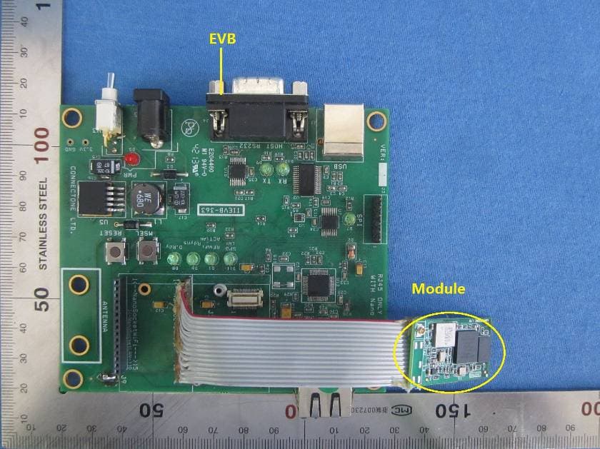
XM5-SMG2SMT
Oct 12, 2014BRD-SMG2SMT-xx
Equipment Class
DTS - Digital Transmission System
XM5-MDLWMGMR09
Feb 26, 2014C1 Wireless b/g baseband
Equipment Class
DTS - Digital Transmission System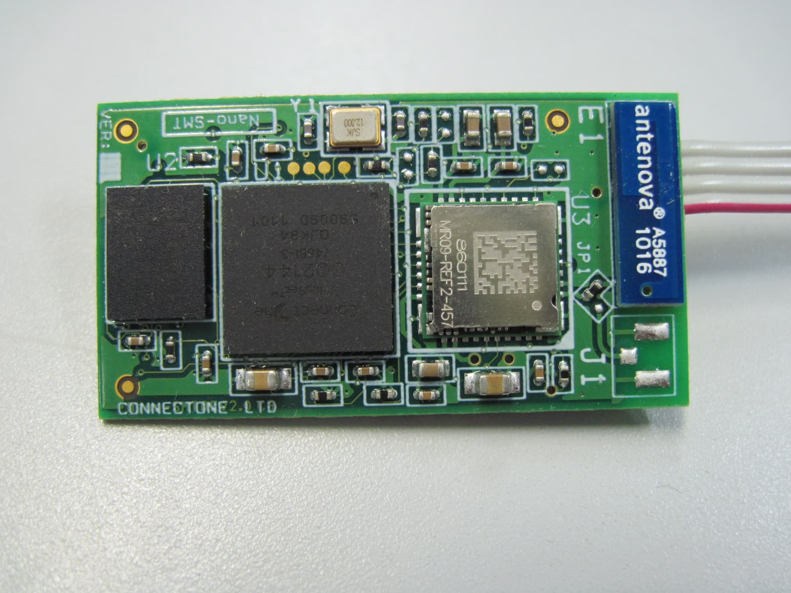
XM5-SM2144SMT
Jul 17, 2011WIFI MODULE
Equipment Class
DTS - Digital Transmission System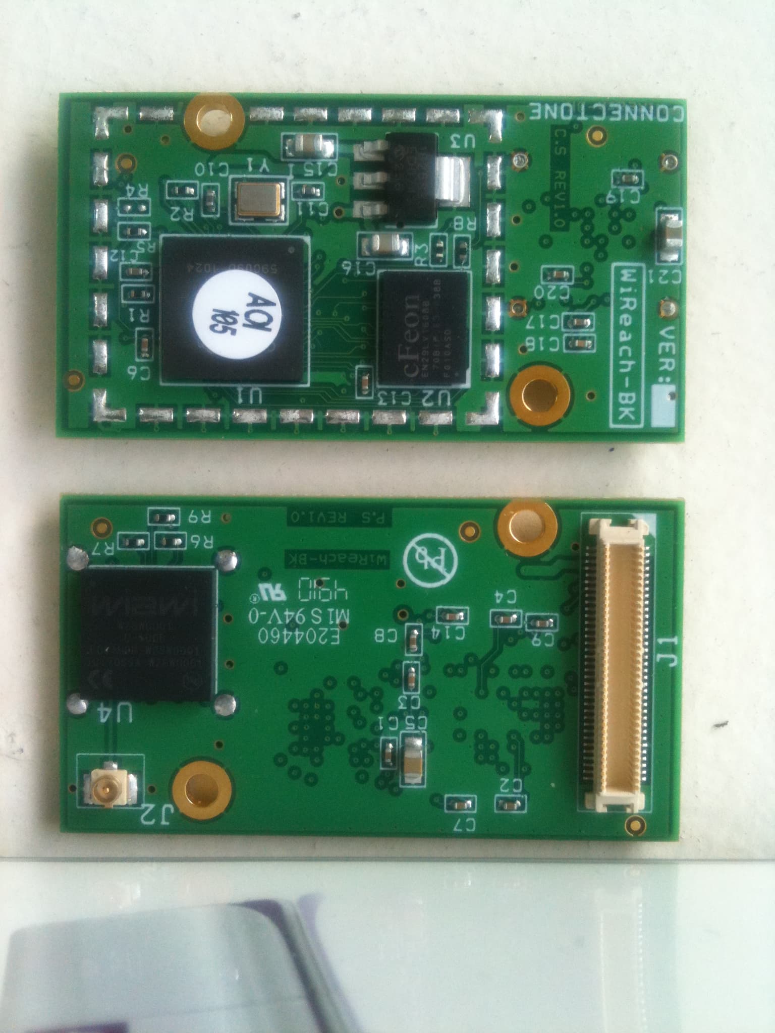
XM5-SM2144N2BIO
Feb 15, 2011WIFI MODULE
Equipment Class
DTS - Digital Transmission System