XMK-MMXTRNB003MIMO UHF FIXED LINK TRANSCEIVER
MiMOMax Wireless Limited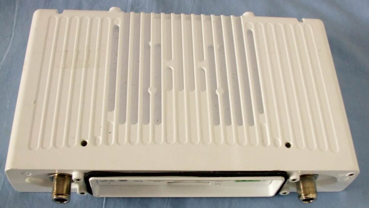
Click to zoom
Application Details
- Equipment Class
- TNB - Licensed Non-Broadcast Station Transmitter
- Date of Grant
- Oct 27, 2015
- Application Purpose
- Original Equipment
- Date of Application
- Oct 27, 2015
- Equipment Note
- MIMO UHF FIXED LINK TRANSCEIVER
- Frequency Range
- 952.00000000 - 960.00000000
- Company
- MiMOMax Wireless Limited
- Country
- New Zealand
Documents & Files
Document Text
Text extracted from the exhibit documents filed with the FCC. Open a document above to read the original.
Attestation Statements
EMC Technologies NZ Ltd PO Box 68-307 Newton Auckland 7th September 2015 FCC ID: XMK-MMXTRNB003 FCC Part 15 Testing Attestation To whom it may concern This letter it to attest that the MiMOMax MWL-TORNADO *E/F/G A/B/C* Fixed Digital Transceiver has been tested by this laboratory to FCC part 15, Sections A and B, sections 15.107, 15.109 and 15.111 and was found to comply. Testing was carried out to Part 15 as the device contains a digital device with Ethernet, RS- 232 and USB ports and it also contains a receiver. The verification compliance process has been applied to this device as: - the receiver is contained within a transceiver - the transceiver will marketed for use exclusively in a commercial/business environment and will therefore be classed as a Class A device Yours faithfully, Andrew Cutler General Manager
External Photos
_________________________________________________________________________________________________________________________________________________________________________ Page 28 of 30 Test Report No 150618.2 20 th August 2015 This report may not be reproduced except in full. 10. PHOTOGRAPHS Back Bottom FRONT LEFT RIGHT
ID Label/Location Info
53.5 24 66 58 142 MJGORIGINAL SHT 1 OF 1 IPN: - DO NOT SCALE OFF DRG IF IN DOUBT ASK! ORIGINAL SCALE: 1:1 DRAWING SIZE : A3 MATERIAL: - FINISH : - DATEAPVDCHKDDRWNAMENDMENTSISS 17-Sep-14A TORNADO LABELING PO Box 1645 Christchurch, New Zealand Tel: 64 3 358 3399 Fax: 64 3 358 0340 CONFIDENTIAL: This document is not to be copied nor the contents passed on to any third party without the written consent of MiMOMax Wireless Ltd. GENERAL LIMITS (UNLESS STATED) LINEAR: 0.25 HOLES : 0.10 ANGLES: 1 ALL DIMENSIONS IN mm. COMPLIANCE LABEL PRODUCT INFO LABEL _________________________________________________________________________________________________________________________________________________________________________ Page 28 of 30 Test Report No 150618.2 20 th August 2015 This report may not be reproduced except in full. 10. PHOTOGRAPHS
Internal Photos
TORNADO_OPEN_IN_CHASSIS DIG_BOARD_IN_CHASSIS DIGITAL_BOARD_BOTTOM_SIDE_NO_SHIELDS DIGITAL_BOARD_BOTTOM_SIDE_WITH_SHIELDS DIGITAL_BOARD_TOP_SIDE_NO_SHIELDS DIGITAL_BOARD_TOP_SIDE_WITH_SHIELDS AND MEZZANINE DIGITAL_BOARD_TOP_SIDE_WITH_SHIELDS RF_BOARD_IN_CHASSIS RF_BOARD_BOT_NO_SHIELDS RF_BOARD_BOT_WITH_SHIELDS RF_BOARD_TOP_NO_SHIELDS RF_BOARD_TOP_WITH_SHIELDS Duplexer 800 MHz 4+4 Cavity
Parts List/Tune Up Info
© MiMOMax Tornado Transmitter Tune-up Procedure V1.01 – October 2015 MIMOMAX TORNADO TRANSMITTER TUNE-UP PROCEDURE OVERVIEW 1.1 All power calibration is done at maximum average output power of +24dBm. This is calibrated at manufacture to within +/-0.2dB. Power is not required to be calibrated for changing to a lower power level as this algorithmically derived from the maximum power calibration. The settable power range is 0 to +24dBm in 0.5dB steps. The tolerance of power across the settable range is defined by the tolerance of the power calibration at maximum. As such a +/-0.2dB tolerance at maximum power calibration will dictate a +/-0.2dB tolerance at any set power within 0 to +24dBm. EQUIPMENT REQUIRED: POWER METER 1.2 For accurate measurement of average power from MiMOMax transmitters a thermistor bolometer type of power meter (e.g. HP435A or similar) is required. Other types of power meter may give inaccurate average power readings when used with MiMOMax transmitters, and may be suitable only for relative power measurement. POWER CALIBRATION 1.3 Figure 1 shows the Tx Power Calibration page in the “Configuration and Control Monitoring System” (CCMS). The calibration method is easy to follow using the instruction panel on the right of the screen. In summary:- Read the power value and enter it into the Tx1 Measured Power text box Press Calibrate Once Tx1 is calibrated buttons will appear that allow you to re-calibrate Tx1. This is a good method of checking that the original calibration is accurate as the Tx will key up and allow you to measure the power. In addition a next button will appear that will allow you to calibrate channel 2 power. Ensure that your power meter is connected to channel 2 before selecting ‘Next’. On calibrating Tx2 and selecting ‘Done’ this will cause CCMS to exit the calibration menu and remove associated warnings. Figure 1: Tx Power Calibration © MiMOMax Tornado Transmitter Tune-up Procedure V1.01 – October 2015 POWER SETTING 1.4 The output power level can be set on the RF Tx and Rx page. Its range is between +0 to +24 dBm in 0.5dB steps. The power can be specified in either dBm or mW, by selecting either dBm or mW as the transmitter power unit. The power cannot be set beyond a maximum of +24dBm (250mW) or below 0dBm (1mW). Figure 2 Transmitter Power Setting 952.025 928.025
RF Exposure Info
_________________________________________________________________________________________________________________________________________________________________________ Page 26 of 30 Test Report No 150618.2 20 th August 2015 This report may not be reproduced except in full. Radio Frequency Hazard Information As per FCC KDB 447498 D01 and Section 2.1091 radio frequency transmitters are required to be operated in a manner that ensures the public is not exposed to RF energy levels. Calculations have been made using the General Public/Uncontrolled Exposure limits that are defined in Section 1.1310. Minimum safe distances have been calculated below. As this radio can operate over the range of 928 – 960 MHz the lowest frequency of operation in the USA, which will give the worst case result, would be 928 MHz. Power density, mW/cm 2 = E 2 /3770 - General Population / Uncontrolled exposure limit will be 0.619 mW/cm 2 (f/1500 = 928 MHz/1500) The minimum distance from the antenna at which the MPE is met is calculated from the equation relating field strength in V/m, transmit power in watts, transmit antenna gain, transmitter duty cycle and separation distance in metres: Power Density = 0.63 mW/cm 2 = E 2 /3770 E= √0.619*3770 E = 48.3 V/m The rated maximum transmitter power = 0.25 watts (+24 dBm). A duty cycle of 100% as the transmitter is a base station could possibly be operated for long periods of time. The client has declared that this transmitter can be operated using a range of antennas with various gains, as detailed in the table below. Antenna Gain Max Gain Safe Distance Safe Distance Type (dBi) (G) (Metres) (cm) Panel Antenna 16.0 39.8 0.359 35.8 12.5 17.8 0.239 23.9 10.0 10.0 0.179 17.9 Omni Directional 8.0 6.3 0.142 14.2 5.0 3.2 0.101 10.1 A sample calculation for the safe distance would be: d = √ (30 * P * G*DC) / E d = √ (30 * 0.25 * 39.8 * 1.0) / 48.3 d = 0.358 metres or 35.8 cm Result: Complies if the safe distances defined above are applied.
Test Report
_________________________________________________________________________________________________________________________________________________________________________ Page 1 of 28 Test Report No 150618.2 20 th August 2015 This report may not be reproduced except in full. EMC Technologies (NZ) Ltd PO Box 68-307 Newton, Auckland Phone 09 360 0862 Fax 09 360 0861 E-Mail Address: [email protected] Web Site: www.emctech.com.au TEST REPORT MiMOMax MWL-TORNADO *E/F/G A/B/C* Fixed Digital Transceiver tested to the Code of Federal Regulations (CFR) 47 Part 101 –Fixed Microwave Services for MiMOMax Wireless Ltd Testing carried out by; ______________________________________ Douglas Poole - Radio Testing Officer This Test Report is issued with the authority of: ______________________________________ Andrew Cutler - General Manager _________________________________________________________________________________________________________________________________________________________________________ Page 2 of 28 Test Report No 150618.2 20 th August 2015 This report may not be reproduced except in full. Table of Contents 1. STATEMENT OF COMPLIANCE 3 2. RESULTS SUMMARY 3 3. INTRODUCTION 3 4. CLIENT INFORMATION 4 5. DESCRIPTION OF TEST SAMPLE 4 6. ATTESTATION 6 7. TEST RESULTS 7 8. TEST EQUIPMENT USED 25 9. ACCREDITATIONS 25 10. PHOTOGRAPHS 26 _________________________________________________________________________________________________________________________________________________________________________ Page 3 of 28 Test Report No 150618.2 20 th August 2015 This report may not be reproduced except in full. 1. STATEMENT OF COMPLIANCE The MiMOMax MWL-TORNADO*E/F/G A/B/C* Fixed Digital Transceiver complies with the Code of Federal Regulations (CFR) 47 Part 101 – Fixed Microwave Services. 2. RESULTS SUMMARY The results of testing, carried out in July 2015 are summarised below. Clause Description Result 101.107 Frequency tolerance Complies 101.109 Bandwidth Complies 101.111 Emission limitations Spurious emission at antenna port Spurious emissions field strength Complies Complies Complies 101.113 Transmitter power limitations Complies 1.1310 Radio frequency exposure limits Complies 3. INTRODUCTION This report describes the tests and measurements performed for the purpose of determining compliance with the specification. The client selected the test sample. This report relates only to the sample tested. This report contains no corrections or erasures. Measurement uncertainties with statistical confidence intervals of 95% are shown below test results. Both Class A and Class B uncertainties have been accounted for, as well as influence uncertainties where appropriate. _________________________________________________________________________________________________________________________________________________________________________ Page 4 of 28 Test Report No 150618.2 20 th August 2015 This report may not be reproduced except in full. 4. CLIENT INFORMATION Company Name MiMOMax Wireless Ltd Address 540 Wairakei Road Christchurch Country New Zealand Contact Mr Paul Reid 5. DESCRIPTION OF TEST SAMPLE Brand Name MiMOMax Model Number MWL-TORNADO *E/F/G A/B/C* Product Fixed Digital Transceiver Manufacturer MiMOMAX Wireless Ltd Manufactured in New Zealand Designed in New Zealand Serial Numbers 26901718 FCC ID XMK-MMXTRNB003 The sample tested has the following specifications: Rated Transmitter Output Power Two transmitters each outputting +24 dBm (0.25 Watt) average Transmitter FC Frequency Bands 928.0 – 929.0 MHz 932.5 – 935.0 MHz 941.0 – 941.5 MHz 941.5 – 944.0 MHz 952.0 – 958.0 MHz 958.0 – 960.0 MHz Testing was performed on a single frequency that is representative of the performance of the radio over the range 928.0 – 960.0 MHz _________________________________________________________________________________________________________________________________________________________________________ Page 5 of 28 Test Report No 150618.2 20 th August 2015 This report may not be reproduced except in full. Test frequencies – Transmit 952.0250 MHz Test frequencies – Receive 928.0250 MHz Channel bandwidths 12.5 kHz, 25.0 kHz, 50.0 kHz Declared Authorised Bandwidths 10.0 kHz, 20 kHz, 41 kHz Modulation Types QPSK, QAM16, QAM64, QAM256 Emission Designators / Modes of operation 10k0W1W – digital speech and data 20k0W1W – digital speech and data 41k0W1W – digital speech and data Power Supply DC voltage supply over the range of 10.5 Vdc to 60 Vdc Typically 12.0 Vdc or 24.0 Vdc using lead acid batteries Standard Temperature and Humidity Temperature: +15C to + 30 maintained. Relative Humidity: 20% to 75% observed. Standard Test Power Source Standard Test Voltage: 24.0 Vdc Extreme Test Voltages High Voltage: 60.0 Vdc Low Voltage: 10.5 Vdc Extreme Temperature High Temperature: + 50C maintained. Low Temperature: - 30 C maintained. _________________________________________________________________________________________________________________________________________________________________________ Page 6 of 28 Test Report No 150618.2 20 th August 2015 This report may not be reproduced except in full. 6. ATTESTATION This report describes the tests and measurements performed for the purpose of determining compliance with the specification with the following conditions: The client selected the test sample. The report relates only to the sample tested. This report does not contain corrections or erasures. Measurement uncertainties with statistical confidence intervals of 95% are shown below test results. Both Class A and Class B uncertainties have been accounted for, as well as influence uncertainties where appropriate. All compliance statements have been made with respect of the specification limit with no reference to the measurement uncertainty. In addition this equipment has been tested in accordance with the requirements contained in the appropriate FCC regulations. To the best of my knowledge, these tests were performe…
Text truncated - open the document above for the full version.
Contact Information
Applicant
Paul Reid
Test Firm
EMC Technologies NZ Ltd.Andrew Cutler
Technical Specifications
| # | Rule Parts | Frequency Range | Power Output | Emission | Tolerance |
|---|---|---|---|---|---|
| 18 | 101 | 952 MHz - 960 MHz | 250.00 mW | 41K0W1W | 0.41 ppm |
Other Applications from MiMOMax Wireless Limited
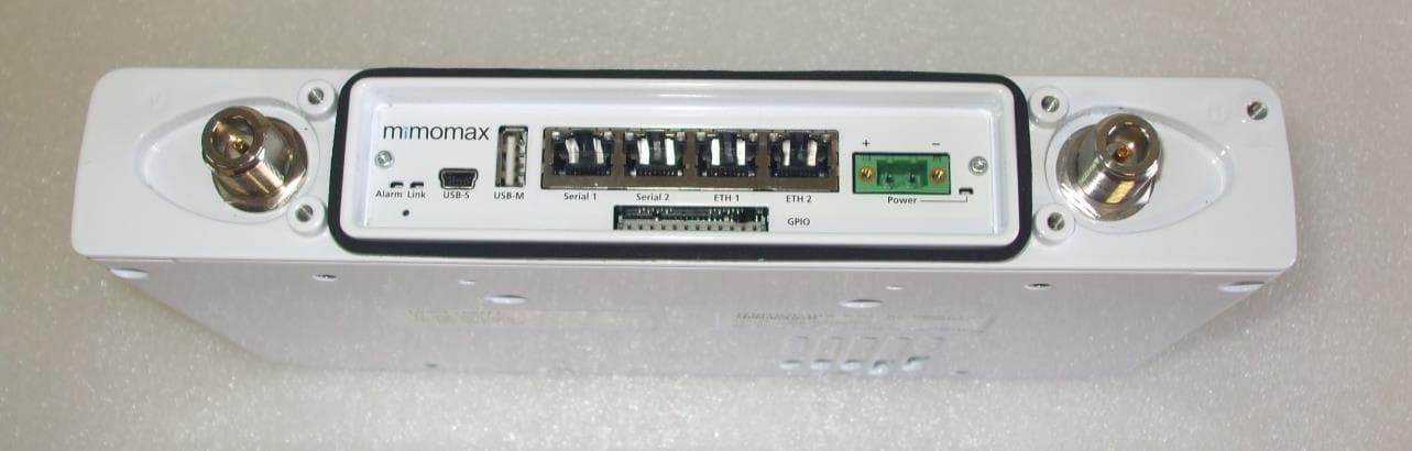
XMK-MMXTRNB009
Oct 02, 2024MiMOMax MWL-TORNADO- A Fixed Digital Microwave Transceiver
Equipment Class
TNB - Licensed Non-Broadcast Station TransmitterXMK-MMXTRNXB006
Mar 14, 2024900MHz TornadoX Transceiver
Equipment Class
CXX - Communications Rcvr for use w/ licensed Tx and CBs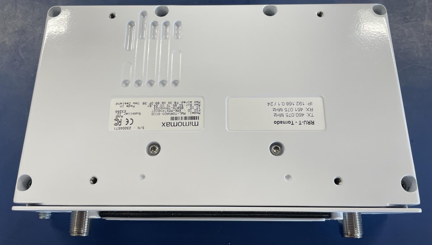
XMK-MMXTRNB007
Feb 18, 2024MiMOMax MWL-Tornado - BCCA Digital Linking Radio
Equipment Class
TNB - Licensed Non-Broadcast Station Transmitter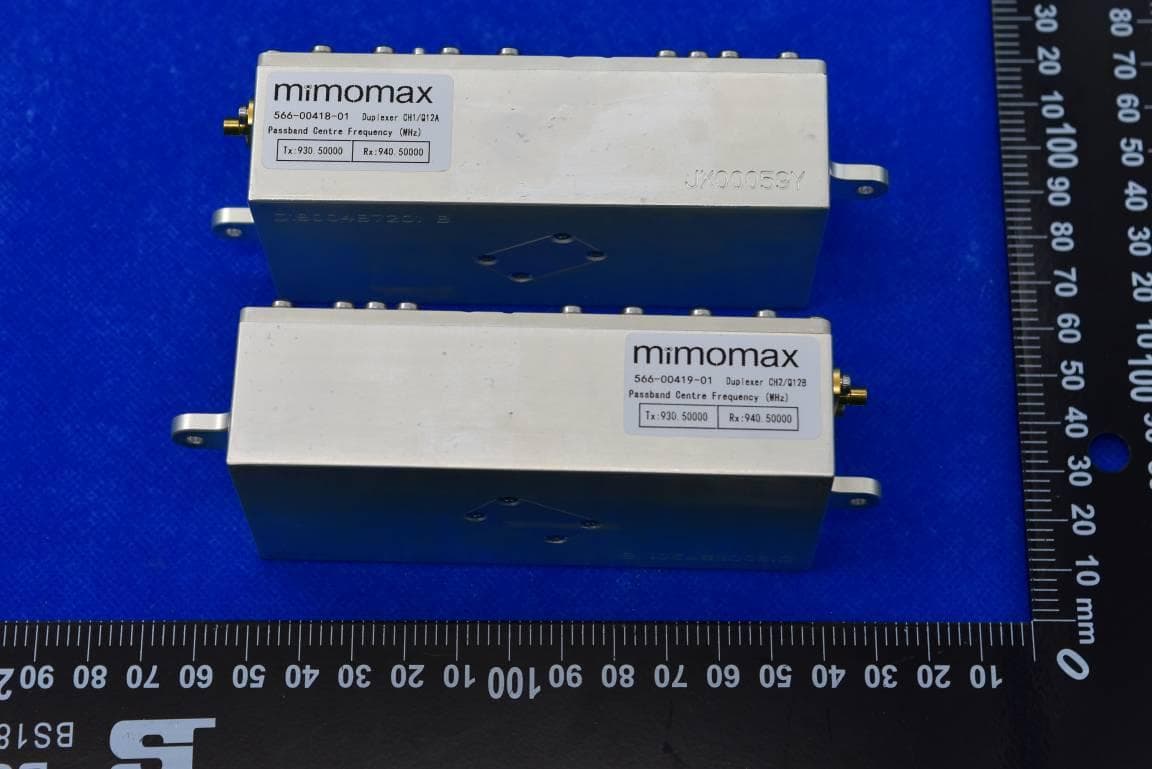
XMK-MMXTRNXB005
Nov 19, 2023900MHz TornadoXR Transceiver
Equipment Class
CXX - Communications Rcvr for use w/ licensed Tx and CBs
XMK-MMXPYXH002
Jul 26, 2023700MHz Pyxis Transceiver
Equipment Class
JBP - Part 15 Class B Computing Device Peripheral