XRSCRMXNOVA101Wireless Light Control Module
LumenRadio AB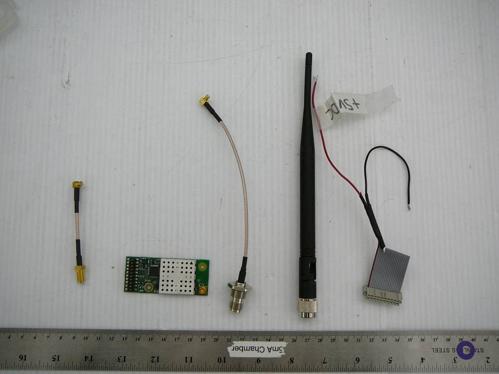
Click to zoom
Application Details
- Equipment Class
- DSS - Part 15 Spread Spectrum Transmitter
- Date of Grant
- Mar 31, 2010
- Application Purpose
- Original Equipment
- Date of Application
- Mar 31, 2010
- Equipment Note
- Wireless Light Control Module
- Frequency Range
- 2402.00000000 - 2480.00000000
- Company
- LumenRadio AB
- Country
- Sweden
Documents & Files
Document Text
Text extracted from the exhibit documents filed with the FCC. Open a document above to read the original.
Users Manual
1(11) LumenRadio CRMX-PD and -PR family DMX and RDM enabled transmitter and receiver modules. Rev. C – September 18, 2009 1 General The CRMX-PD family is the future of wireless DMX and RDM distribution – a wireless system that communicates reliably with perfect fidelity. CRMX-PD is the most powerful wireless lighting control system on the market, with ground breaking features to ensure unrivalled reliability. CRMX-PD distributes DMX and RDM with full frame integrity and provides range and reliability that surpass all other systems available today. The CRMX-PD cards are designed to be small enough to fit into any standard fixture or controller and have an interface that easily connects to existing user interfaces. CRMX- PD cards are also compatible with W-DMX™ equipment for easy integration into legacy systems. CRMX™ is trademarked, patent pending, CE approved and FCC approval pending as of April 2009. Two main families in the CRMX range of OEM products are found: • CRMX-PD, DMX enabled transmitter and receiver modules. • CRMX-PR, RDM enabled transmitter and receiver modules. 2 Features • Cognitive coexistence dynamically avoids occupied frequencies • Compliance with USITT DMX-512 (1986 & 1990) and 512-A • Full DMX fidelity and frame integrity • Auto sensing of DMX frame rate and frame size • <5ms DMX latency • W-DMX™ 1 compatible receiver • Standard 2,54 x 2,54mm (0,1 x 0,1”) 2x10 position interface connector • MCX type RF connector or optional integral antenna • All configuration data is stored in a non volatile memory, 20 year retention. • Up to 512 receivers may be used with every transmitter 1 W-DMX™ is a trademark of Wireless Solution Sweden AB 2(11) 3 Pinout Figure 1 CRMX-PD/PR family DMX/RDM enabled PCB Pin Type Description 1 Reserved Do not connect, unimplemented feature 2 Reserved Do not connect, unimplemented feature 3 Power Unregulated DC input 6 - 12V Warning! 4 Power GND 5 Power Regulated 5V Warning! 6 O Status LED output 7 I Connect function switch input 8 I/O DMX + 9 I/O DMX - 10 Power GND 11 O PWM Red (future implementation) 12 O PWM Green (future implementation) 13 O PWM Blue (future implementation) 14 I/O SPI SCK (future implementation) 15 I/O SPI M ISO (future implementation) 16 I/O SPI MOSI (future implementation) 17 I/O SPI Slave Select optionally general I/O (future implementation) 18 I/O A/D converter 1 optionally general I/O (future implementation) 19 I/O A/D converter 2 optionally general I/O (future implementation) 20 I/O A/D converter 3 optionally general I/O (future implementation) Warning! Do not connect power to pin 3 and 5 simultaneously. The card will be permanently damaged. Pin 1 designator MCX type RF connector 3(11) 4 Specifications Min. Typ. Max. Units DMX latency 5 ms Supported DMX frame rate receiver 1 830 2 Hz Supported DMX frame rate transmitter 0,8 7352 Hz Unregulated low voltage input 6 12 VDC Regulated low voltage input 4,9 5,0 5,1 VDC Current consumption receiver 130 3 mA Current consumption transmitter 250 4 mA Function switch low level input 0,8 V Function switch high level input 2,0 V LED indicator voltage output 3,3V V LED indicator current output 20 mA Frequency hopping rate 650 μs Operational frequency range 2402 2480 MHz RF output in high power mode 300 5 mW RF output in normal power mode 100 mW RF output in low power mode 50 10 mW mW Sensitivity at 0.1% Packet Error Rate -96 dBm Recovery time upon loss of signal <1 s Operating temp range (ambient) -20 -4 +75 +167 °C °F • Upon loss of DMX, transmitter module will timeout after 1,25s • Upon loss of RF link or DMX, receiver modules will go into high impedance state 2 Limited by the DMX512-A standard 3 Both on regulated and unregulated input 4 Both on regulated and unregulated input 5 Allowed in US only 4(11) 5 Typical application circuit Figure 2 Typical application circuit Both the 120 Ω and 4k7 Ω resistors are required 5(11) 6 User interface A user interface may be created using a normally open momentary switch for operation and a LED for status indication. A green power indicator LED is found onboard which is lit if a DC power level within specified range is present, see Figure 2 on page 2 Note! The user interface is mandatory for proper operation of the CRMX-PD cards. Figure 3 Location of power indicator LED The switch found in Figure 2 on page 2 is used to operate transmitters and receivers which is done by closing the switch and follow the timing requirements below. The switch should pull pin 7 to ground when closed. Pin7 is pulled high by a resistor when the switch is opened. Transmitter mode Switch timing Logic level Idle Open High Link receivers 50ms ↔ 3s Low Unlink all receivers >3s Low Receiver mode Switch timing Logic level Idle Open High Unlink transmitter >3s Low The LED indicator pin is a 3,3V output capable of driving 20mA. An appropriate series resistor must be used to limit the current output from the pin to maximum 20mA . LED indication is depending on receiver or transmitter and is illustrated below. Power indicator LED 6(11) 6.1 LED indicator receiver 6.2 LED indicator transmitter Off (0V) not linked to any transmitter On (3,3V) 100ms / Off (0V) 900ms linked to a transmitter no DMX data received. On (3,3V) linked to a transmitter and receiving DMX data On (3,3V) 100ms / Off (0V) 100ms attempting to link to transmitter On (3,3V) 100ms / Off (0V) 900ms transmitter operational no DMX data found. On (3,3V) DMX data found and transmitted. On (3,3V) 100ms / Off (0V) 100ms attempting to link receivers On (3,3V) 500ms / Off (0V) 500ms unlinking all powered linked receivers 7(11) 7 Mechanical dimensions An AutoCad dxf file with all relevant dimensions is available on request from LumenRadio. The two holes on the PCB are designed for 2,54mm (0.1”) snap in standoffs. For example the Richco DLCBST series may be used. The shielding cage is only present on transmitter cards. 27,5 22,0 4,4 19,1 59,9 65 All dimensions in mm Ø2,54 Ø2,54 8(11) 8 Connecting the CRMX OEM card • The RP - T…
Text truncated - open the document above for the full version.
Cover Letter(s)
FCC Confidential Authorization January 29, 2010 FEDERAL COMMUNICATIONS COMMISSIONS Authorization and Evaluation Division 7435 Oakland Mills Road Columbia, MD 21046 Subject: Confidentiality Request regarding application for certification of FCC ID: XRSCRMXNOVA101 In accordance with Sections 0.457 and 0.459 of the Commission’s Rules, LumenRadio AB hereby requests long-term confidential treatment of information accompanying this application as outlined below: • Block Diagram • Schematics • Operation Description The above materials contain proprietary and confidential information not customarily released to the public. The public disclosure of these materials provides unjustified benefits to its competitors in the market. Sincerely, Niclas Norlén, CTO LumenRadio AB Stena Center 1 SE-41292 Gothenburg Sweden
Cover Letter(s)
Modular approval letter To whom it may concern. LumenRadio radio module with FCC ID: XRSCRMXNOVA101: 1. Does have its own RF shielding. 2. Does have buffered modulation inputs. 3. Does have its own power supply regulation 4. Does comply with the antenna requirements of Section 15.203 and 15.204(c) 5. Is tested in a stand-alone configuration according to applicable requirements 6. Is labeled with its own FCC ID. If the label is not visible when installed inside another device this device must have a label visible on the outside containing he text “Contains FCC ID: XRSCRMXNOVA101” 7. The operating requirements found in the document: “CRMX-PD and RD specification ” 8. The Product is an intentional radiator of Radio Frequency (RF) energy. In order to limit RF exposure to personnel in the immediate area, the Product should be located and installed such that a separation of at least 20 centimeters is maintained between the product’s antenna and personnel in the vicinity of the device. Niclas Norlén CTO, LumenRadio +46 31 772 80 84
External Photos
LumenRadio AB FCC ID: XRSCRMXNOVA101, IC: 8879A:CRMXN101 Report Number: R1002024-247 Page 49 of 51 FCC Part 15.247 & IC RSS-210 Test Report 18 EXHIBIT C - EUT Photographs 18.1 EUT - Top View 18.2 EUT - Bottom View LumenRadio AB FCC ID: XRSCRMXNOVA101, IC: 8879A:CRMXN101 Report Number: R1002024-247 Page 50 of 51 FCC Part 15.247 & IC RSS-210 Test Report 18.3 EUT- Complete Setup Top View 18.4 EUT – Antenna Top View
ID Label/Location Info
LumenRadio AB FCC ID: XRSCRMXNOVA101, IC: 8879A:CRMXN101 Report Number: R1002024-247 Page 45 of 51 FCC Part 15.247 & IC RSS-210 Test Report 16 EXHIBIT A – FCC & IC Labeling Requirement 16.1 FCC ID Label Requirements As per FCC §2.925, (a) Each equipment covered in an application for equipment authorization shall bear a nameplate or label listing the following: (1) FCC Identifier consisting of the two elements in the exact order specified in §2.926. The FCC Identifier shall be preceded by the term FCC ID in capital letters on a single line, and shall be of a type size large enough to be legible without the aid of magnification. Example: FCC ID XXX123. XXX—Grantee Code 123—Equipment Product Code As per FCC §15.19, (a) In addition to the requirements in part 2 of this chapter, a device subject to certification, or verification shall be labeled as follows: (3) All other devices shall bear the following statement in a conspicuous location on the device: This device complies with part 15 of the FCC Rules. Operation is subject to the following two conditions: (1) This device may not cause harmful interference, and (2) this device must accept any interference received, including interference that may cause undesired operation. (4) Where a device is constructed in two or more sections connected by wires and marketed together, the statement specified above is required to be affixed only to the main control unit. If the EUT is integrated within another device then a label affixed to the host shall also state, “Contains FCC ID: XXXXXX” (5) When the device is so small or for such use that it is not practicable to place the statement specified under paragraph (a) of this section on it, the information required by this paragraph shall be placed in a prominent location in the instruction manual or pamphlet supplied to the user or, alternatively, shall be placed on the container in which the device is marketed. However, the FCC identifier or the unique identifier, as appropriate, must be displayed on the device. 16.2 IC Label Requirements As per IC RSS-Gen §5, the certification number shall appear as follows: IC: XXXXXX-YYYYYYYY Where: • "XXXXXX-YYYYYYYY" is the certification number • "XXXXXX" is the Certificate Holder Number (CHN), made of at most 6 alphanumeric characters (A-Z, 0-9), assigned by Industry Canada; and • "YYYYYYYY" is the Unique Product Number (UPN), made of at most 11 alphanumeric characters (A-Z, 0-9) assigned by the applicant. • Note 1: The term "IC" before the equipment certification number only signifies that the Industry Canada technical specifications were met. • Note 2: Note 1 shall be conspicuously placed in the equipment user manual. • Note 3: Permitted alphanumeric characters used in the CHN and UPN are limited to capital letters (A-Z) and digits (0-9). Other characters, such as "#", "/" or "-", shall not be used. LumenRadio AB FCC ID: XRSCRMXNOVA101, IC: 8879A:CRMXN101 Report Number: R1002024-247 Page 46 of 51 FCC Part 15.247 & IC RSS-210 Test Report As per RSS-Gen §5.2 Equipment Labeling: Equipment subject to certification under the applicable RSS, shall be permanently labeled on each item, or as an inseparable combination. The label must contain the following information for full compliance: (a) the certification number, prefixed by the term “IC:”; (b) the manufacturer's name, trade name or brand name; and (c) a model name or number. Equipment for which a certificate has been issued is not considered certified if it is not properly labeled. The information on the Canadian label can be combined with the manufacturer’s other labeling requirements. If the device size is too small to put a label, the label can be included in the user’s manual, upon agreement with Industry Canada. 16.3 FCC ID & IC Label Content 16.4 FCC ID & IC Label Location on EUT Label here
Internal Photos
LumenRadio AB FCC ID: XRSCRMXNOVA101, IC: 8879A:CRMXN101 Report Number: R1002024-247 Page 51 of 51 FCC Part 15.247 & IC RSS-210 Test Report 18.5 EUT - RF Shielding off Top View ***** END OF REPORT *****
RF Exposure Info
LumenRadio AB FCC ID: XRSCRMXNOVA101, IC: 8879A:CRMXN101 Report Number: R1002024-247 Page 43 of 51 FCC Part 15.247 & IC RSS-210 Test Report 15 §FCC 15.247(i) & IC RSS-102 - RF Exposure 15.1 Applicable Standard According to FCC §15.247(i) and §1.1307(b)(1), systems operating under the provisions of this section shall be operated in a manner that ensures that the public is not exposed to radio frequency energy level in excess of the Commission’s guidelines. According to FCC §1.1310 and §2.1091 RF exposure is calculated. Limits for General Population/Uncontrolled Exposure Frequency Range (MHz) Electric Field Strength (V/m) Magnetic Field Strength (A/m) Power Density (mW/cm 2 ) Averaging Time (minutes) Limits for General Population/Uncontrolled Exposure 0.3-1.34 614 1.63 *(100) 30 1.34-30 824/f 2.19/f *(180/f 2 ) 30 30-300 27.5 0.073 0.2 30 300-1500 / / f/1500 30 1500-100,000 / / 1.0 30 f = frequency in MHz * = Plane-wave equivalent power density Before equipment certification is granted, the procedure of RSS-102 must be followed concerning the exposure of humans to RF fields. According to IC RSS-102 Issue 4 section 4.2, RF limits used for general public will be applied to the EUT. Frequency Range (MHz) Electric Field (V/m rms) Magnetic Field (A/m rms) Power Density (W/m 2 ) Averaging Time (Minutes) 0.003 - 1 280 2.19 - 6 1 - 10 280 / f 2.19 / f - 6 10 - 30 28 2.19 / f - 6 30 – 300 28 0.073 2* 6 300 – 1 500 1.585 f 0.5 0.0042 f 0.5 f / 150 6 1 500 – 15 000 61.4 0.163 10 6 15 000 – 150 000 61.4 0.163 10 616000 / f 1.2 150 000- 300 000 0.158 f 0.5 4.21 x 10 -4 f 0.5 6.67 x 10 -5 f 616000 / f 1.2 Note: ƒ is frequency in MHz * Power density limit is applicable at frequencies greater than 100 MHz LumenRadio AB FCC ID: XRSCRMXNOVA101, IC: 8879A:CRMXN101 Report Number: R1002024-247 Page 44 of 51 FCC Part 15.247 & IC RSS-210 Test Report 15.2 MPE Prediction Predication of MPE limit at a given distance, Equation from OET Bulletin 65, Edition 97-01 S = PG/4πR² Where: S = power density P = power input to antenna G = power gain of the antenna in the direction of interest relative to an isotropic radiator R = distance to the center of radiation of the antenna Maximum peak output power at antenna input terminal (dBm): 25.03 Maximum peak output power at antenna input terminal (mW): 318.4 Prediction distance (cm): 20 Prediction frequency (MHz): 2402 Maximum Antenna Gain, typical (dBi): 5 Maximum Antenna Gain (numeric): 3.1622 Power density of prediction frequency at 20.0 cm (mW/cm 2 ): 0.2 Power density of prediction frequency at 20.0 cm (W/m 2 ): 2 MPE limit for uncontrolled exposure at prediction frequency (mW/cm 2 ): 1.0 MPE limit for uncontrolled exposure at prediction frequency (W/m 2 ): 10 15.3 Test Result The device is compliant with the requirement MPE limit for uncontrolled exposure. The maximum power density at the distance of 20 cm is 0.2 mW/cm 2 (2 W/m 2 ).Limit is 1 mW/cm 2 (10 W/m 2 ).
Test Report
Note: This test report is prepared for the customer shown above and for the device described herein. It may not be duplicated or used in part without prior written consent from Bay Area Compliance Laboratories Corp. This report must not be used by the customer to claim product certification, approval, or endorsement by NVLAP*, NIST, or any agency of the Federal Government. * This report may contain data that are not covered by the NVLAP accreditation and are marked with an asterisk “*” (Rev.2) FCC PART 15.247 IC RSS-210, ISSUE 7, JUNE 2007 TEST AND MEASUREMENT REPORT For LumenRadio AB Stena Center 1, Gothenburg, Sweden, SE-41292 Report Type: Original Report Product Type: Wireless Transceiver Module Test Engineer: Dennis Huang Report Number: R1002024-247 Report Date: 2010-03-11 Reviewed By: Boni Baniqued EMC/RF Supervisor Prepared By: (84) Bay Area Compliance Laboratories Corp. 1274 Anvilwood Avenue, Sunnyvale, CA 94089, USA Tel: (408) 732-9162, Fax: (408) 732 9164 FCC ID: XRSCRMXNOVA101 IC: 8879A-CRMXN101 LumenRadio AB FCC ID: XRSCRMXNOVA101, IC: 8879A:CRMXN101 Report Number: R1002024-247 Page 2 of 51 FCC Part 15.247 & IC RSS-210 Test Report TABLE OF CONTENTS 1 General Information .............................................................................................................................................. 5 1.1 Product Description for Equipment under Test (EUT) ..............................................................................5 1.2 Mechanical Description of EUT ................................................................................................................ 5 1.3 EUT Photo ................................................................................................................................................. 5 1.4 Objective.................................................................................................................................................... 5 1.5 Related Submittal(s)/Grant(s) .................................................................................................................... 6 1.6 Test Methodology ...................................................................................................................................... 6 1.7 Measurement Uncertainty .......................................................................................................................... 6 1.8 Test Facility ............................................................................................................................................... 6 2 System Test Configuration .................................................................................................................................... 7 2.1 Justification ................................................................................................................................................ 7 2.2 EUT Exercise Software.............................................................................................................................. 7 2.3 Special Accessories.................................................................................................................................... 7 2.4 Equipment Modifications........................................................................................................................... 7 2.5 Internal Parts List and Details.................................................................................................................... 7 2.6 Interface Ports and Cabling........................................................................................................................ 7 3 Summary of Test Results ....................................................................................................................................... 8 4 FCC §15.203 & IC RSS-Gen §7.1.4 - Antenna Requirement ............................................................................. 9 4.1 Applicable Standard................................................................................................................................... 9 4.2 Antenna Connected Construction .............................................................................................................. 9 5 FCC §15.207 & IC RSS-GEN §7.2.2- Conducted Emissions .............................................................................. 10 5.1 Applicable Standard................................................................................................................................. 10 5.2 Test Setup ................................................................................................................................................ 10 5.3 Test Procedure ......................................................................................................................................... 10 5.4 Test Results.............................................................................................................................................. 10 6 FCC §15.205, §15.209 & §15.247(D) & IC RSS-210 §2.2, §8.5 – Restrict Band and Unwanted Emissions .... 11 6.1 Applicable Standard:................................................................................................................................ 11 6.2 Test Setup ................................................................................................................................................ 12 6.3 Test Setup Diagram ................................................................................................................................. 12 6.4 Test Procedure ......................................................................................................................................... 13 6.5 Corrected Amplitude & Margin Calculation............................................................................................ 13 6.6 Test Equipment List and Details ...............…
Text truncated - open the document above for the full version.
Test Setup Photos
LumenRadio AB FCC ID: XRSCRMXNOVA101, IC: 8879A:CRMXN101 Report Number: R1002024-247 Page 47 of 51 FCC Part 15.247 & IC RSS-210 Test Report 17 EXHIBIT B – Test Setup Photographs 17.1 Radiated Emissions (Below 1 GHz) – Front View 17.2 Radiated Emissions (Below 1 GHz) – Rear View LumenRadio AB FCC ID: XRSCRMXNOVA101, IC: 8879A:CRMXN101 Report Number: R1002024-247 Page 48 of 51 FCC Part 15.247 & IC RSS-210 Test Report 17.3 Radiated Emissions (Above 1 GHz) – Front View 17.4 Radiated Emissions (Above 1 GHz) – Rear View
Contact Information
Applicant
Michael Karlsson(R&D Manager)
Test Firm
Bay Area Compliance LaboratoryJohn Chan
Technical Specifications
| # | Rule Parts | Frequency Range | Power Output |
|---|---|---|---|
| 1 | 15C | 2.40 GHz - 2.48 GHz | 318.40 mW |
Other Applications from LumenRadio AB
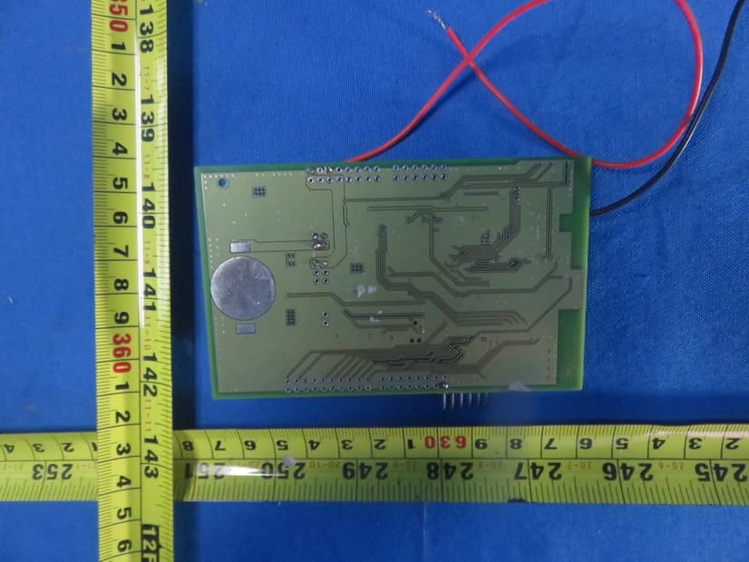
XRSMLEN201
Apr 22, 2021SRD device for operation in the 2.45GHz band
Equipment Class
DTS - Digital Transmission System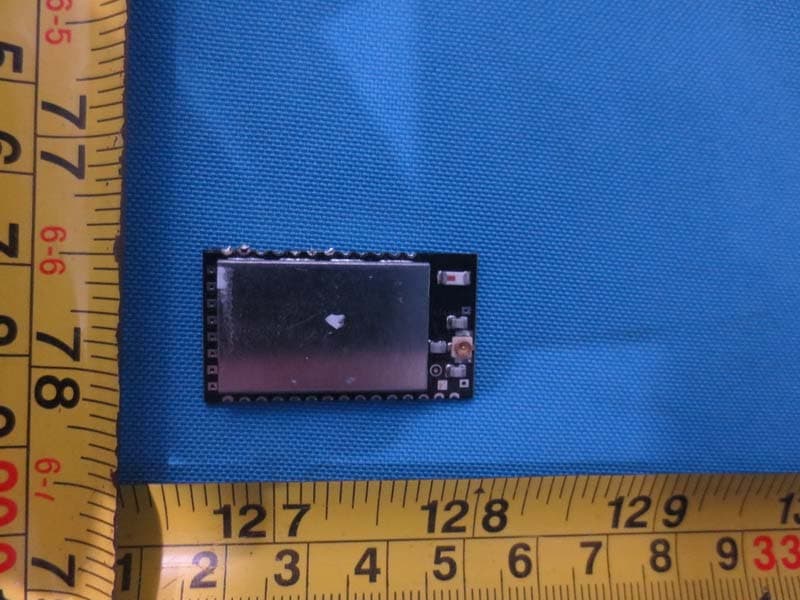
XRSCRMXTIMO101
Apr 18, 20152.4G Wireless Control Module
Equipment Class
DSS - Part 15 Spread Spectrum Transmitter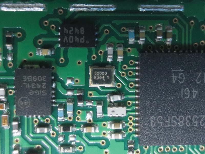
XRSCRMXCORE101
Mar 16, 20152.4G Wireless Control Module
Equipment Class
DTS - Digital Transmission System
XRSCRMXCORE102
Mar 06, 20152.4G Wireless Control USB Dongle
Equipment Class
DTS - Digital Transmission System