XSG832876Battery operated window opener
VELUX America Inc.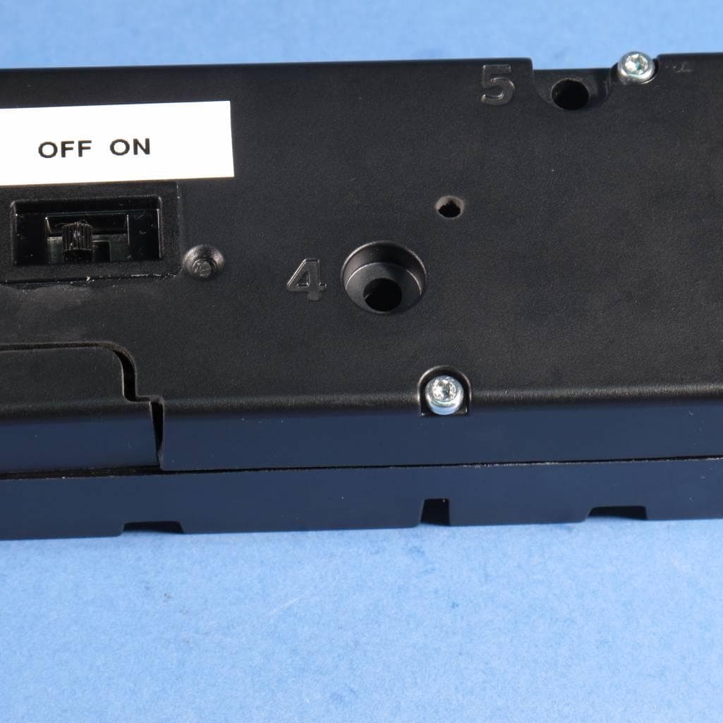
Click to zoom
Application Details
- Equipment Class
- DTS - Digital Transmission System
- Date of Grant
- Feb 13, 2013
- Application Purpose
- Original Equipment
- Date of Application
- Feb 10, 2013
- Equipment Note
- Battery operated window opener
- Frequency Range
- 2425.00000000 - 2475.00000000
- Company
- VELUX America Inc.
- Country
- United States
Documents & Files
Document Text
Text extracted from the exhibit documents filed with the FCC. Open a document above to read the original.
Users Manual
VAS 452672-2011-06 VSE/VCE KLR 100 User manual ENGLISH VELUX 2 Important information / Warnings 4-6 Getting started Initial set-up 8-9 Remote control functions 10-11 Operation Locating and operating a product 12-14 - One skylight 12 - More than one skylight 13-14 Choosing positions 15 Closing the skylight automatically 16 Disabling rain sensor 17 Menu functions Menu guide 18 Navigating through the menus 19 Time and date 20-21 Changing language 22 Room, Group and Zone 23 - Creating a Room 24-25 - Editing a Room 26-27 - Creating a Group 28-29 Naming 30-31 Favorite settings 32-33 Rearranging order 34-35 Programs 37-51 - My program 38-43 - Shortcut P1/P2 44-51 Contents Congratulations on your new VELUX product In order to make the best use of your product please read these instructions on operation and maintenance. VELUX 3 Display 52-53 - Display light 52 - Sleep mode 53 Keypad lock 54 Access code 55 Software version 56 Clearing remote control settings 57 Extending the system Registering new products 58-59 Using additional activation controls 61-65 - Copying to a new remote control 62-63 - Copying to a remote control in operation 64 - Adding products to a remote control in operation 65 - Copying products to other types of activation controls 66-67 Security key 68-69 Resetting Resetting and preparing for registration 70 Resetting the remote control 71 Adjusting the maximum opening 72-73 Fitting of holder for remote control 74-75 Use and maintenance Power failure / Mislaid remote control 76 Maintenance 77 Further information Display symbols 78 Display texts / Glossary 79 VELUX 4 Please keep instructions for future reference and hand them over to any new user. Safety • Before operating ensure that the skylight with electrical products can be operated without risk of damage to property or injury to people or animals. • For personal safety, never have head, hand, arm or any other body part out of or through the opening of the skylight without first having switched off main power supply. • Children must not be allowed to play with the skylight and its electrical products. The remote control should be kept out of reach of children. Do not allow children near an open skylight. • This device is intended for use by persons with the relative experience and knowledge and who have been given instruction concerning use of the device by a person responsible for their safety. • If repair or adjustment work is needed, disconnect from main power sup- ply and ensure that it cannot be reconnected unintentionally. • The main power supply cable is for indoor use only. • It is recommended that a remote control be placed in the room where the skylight and its electrical products have been installed. • If the skylight is positioned within reach, the opening of the skylight operator must be adjusted to reduce the maximum size of the open- ing (see section Adjusting the maximum opening). Failure to make such adjustment can result in serious injury or death. • Make sure that the insect screen is installed before putting the skylight into use. • FCC ID: XSG863829 and IC ID: 8642A-863829: Remote control Certificate of Radio Equipment in Japan: No. 10215191/AA/00 FCC ID: XSG863765 and IC ID: 8642A-863765: Window operator (skylight operator) This device complies with part 15 of the FCC and RSS-210 of the IC rules. Operation is subject to the following two conditions: (1) This device may not cause harmful interference, and (2) this device must accept any interference received, including interference that may cause undesired operation. Important information / Warnings VELUX 5 • This device has been tested and found to comply with the limits for a Class B digital device, pursuant to part 15 of the FCC Rules. These limits are designed to provide reasonable protection against harmful interfer- ence in a residential installation. This device generates, uses and can radi- ate radio frequency energy and, if not installed and used in accordance with the instructions, may cause harmful interference to radio communi- cations. However, there is no guarantee that interference will not occur in a particular installation. If this device does cause harmful interference to radio or television reception, which can be determined by turning the device off and on, the user is encouraged to try to correct the interfer- ence by one or more of the following measures: - Reorient or relocate the receiving antenna. - Increase the separation between the device and receiver. - Connect the device into an outlet on a circuit different from that to which the receiver is connected. - Consult the dealer or an experienced radio/TV technician for help. Changes or modifications not expressly approved by the party respon- sible for compliance could void the user's authority to operate the device. • FCC Radiation Exposure Statement: This device complies with FCC RF radiation exposure limits set forth for an uncontrolled environment • The term "IC:" before the device certification number only signifies that the Industry Canada technical specifications were met. Function • If the rain sensor gets wet, the skylight automatically closes. • Disabling the rain sensor while the skylight is open creates a risk of water to the interior of the building. • To prevent the skylight from closing because of very fine/weak rain, fog or dew, the rain sensor is equipped with a heating element to keep the surface dry. • If the rain sensor is activated, the skylight will close within approximately 30 seconds. If the skylight is activated with the remote control or another activation control, it will take up to one minute until the skylight is completely closed. Therefore, in case of sudden rain, water may enter the room before the skylight is closed. • In case of snow and/or ice, the operation of the skylight may be blocked resulting in damage to the skylight. VELUX 6 Important information / Warnings Product • This product has been designed for use with genuine VELUX products. Con…
Text truncated - open the document above for the full version.
Users Manual
3SM S0* WW Add on to the user guide: All text concerning the main, power cord and similarly will be taken out of the user guide. The below text will be add to the user guide on the relevant pages. Remember that the batteries will not be charged when the switch is off. So in order to charge the batteries the switch must be on.
Cover Letter(s)
Telephone: +45 9980 6245 Fax: +45 9980 6260 E-mail: [email protected] VELUX A/S Accessories Bækgaardsvej 40, DK-6900 Skjern Identity Declaration Manufacture declaration We hereby declare that our motorized window opener model: o 3MX S01 WW mains operated and o 3SM S01 WW and 3SM S02 WW, battery operated Concerning the RF part is identical. VELUX A/S, December 7, 2012 Test Department – L2 Jens Aksel Thomsen Test Engineer, Safety
External Photos
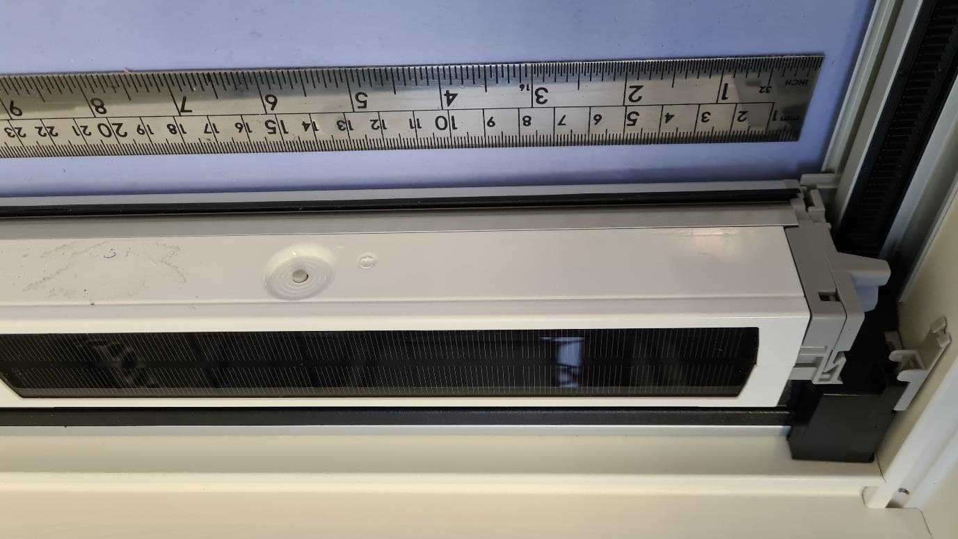
Photographs module 20124202300 External PHOTOGRAPH 1: - VELUX 3SM S01 WW, TOP VIEW ....................................................................................................... 2 PHOTOGRAPH 2: - VELUX 3SM S01 WW, BOTTOM VIEW ................................................................................................ 3 PHOTOGRAPH 4: - VELUX 3SM S01 WW, TORX SCREWS ................................................................................................. 4 Page: 2 of 4 Report number: 20124202300 Photograph 1: - Velux 3SM S01 WW, top view Page: 3 of 4 Report number: 20124202300 Photograph 2: - Velux 3SM S01 WW, bottom view Page: 4 of 4 Report number: 20124202300 Photograph 3: - Velux 3SM S01 WW, torx screws
Internal Photos
Photographs module 20124202302 Internal PHOTOGRAPH 1: - VELUX 3SM S01 WW, INTERNAL VIEW .............................................................................................. 2 PHOTOGRAPH 2: - VELUX 3SM S01 WW, PCB TOP VIEW ............................................................................................... 3 PHOTOGRAPH 3: - VELUX 3SM S01 WW; PCB BOTTOM VIEW ........................................................................................ 4 Page: 2 of 4 Report number: 20124202302 Photograph 1: - Velux 3SM S01 WW, internal view Page: 3 of 4 Report number: 20124202302 Photograph 2: - Velux 3SM S01 WW, PCB top view Page: 4 of 4 Report number: 20124202302 Photograph 3: - Velux 3SM S01 WW; PCB bottom view
Test Report
Radio test report 20124202300 based on: FCC part 15; subpart C; section 15.247 (ed. 10-1- 11); FCC part 15, subpart B, section 15.109 (ed. 10-1-11); IC RSS 210, Annex 8 (issue 8); IC RSS- Gen (issue 3) Battery operated window opener VELUX 3SM S01 WW Report number: 20124202300 Contents MAIN MODULE .............................................................................................................................................. 3 1 ...... INTRODUCTION ...................................................................................................................................... 3 2 ...... PRODUCT ............................................................................................................................................... 4 3 ...... TEST SCHEDULE ..................................................................................................................................... 4 4 ...... PRODUCT DOCUMENTATION ................................................................................................................... 5 5 ...... OBSERVATIONS AND COMMENTS ........................................................................................................... 5 6 ...... MODIFICATIONS TO THE SAMPLE ............................................................................................................ 5 7 ...... SUMMARY.............................................................................................................................................. 5 8 ...... CONCLUSIONS ........................................................................................................................................ 6 TEST RESULTS MODULE ............................................................................................................................ 7 1 ...... GENERAL INFORMATION ........................................................................................................................ 7 1.1 Equipment information ..................................................................................................................... 7 1.2 Tested channels ................................................................................................................................. 7 2 ...... EMISSION TESTS ..................................................................................................................................... 8 2.1 Maximum conducted output power................................................................................................... 8 2.2 Minimum 6 dB bandwidth ................................................................................................................ 9 2.3 99% emission bandwidth ................................................................................................................ 10 2.4 TX unwanted emissions attenuation (conducted, 0.03 - 26 GHz) ................................................... 11 2.5 Power spectral density conducted to the antenna ............................................................................ 12 2.6 Average factor ................................................................................................................................ 13 2.7 TX unwanted emissions in the restricted bands .............................................................................. 14 2.8 RX unwanted emissions (radiated, 0.03 - 1 GHz) ........................................................................... 15 2.9 RX unwanted emissions (radiated, 1 - 13 GHz) .............................................................................. 17 USED TEST EQUIPMENT MODULE ........................................................................................................ 19 CROSS REFERENCE TABLE ..................................................................................................................... 20 REVISION HISTORY ................................................................................................................................... 21 This report comprises of three modules. The total number of pages is: 21 Page: 3 of 21 Main module Report number: 20124202300 Main module 1 Introduction This report contains the result of tests performed by: Telefication B.V. Edisonstraat 12a 6902 PK Zevenaar The Netherlands Telefication complies with the accreditation criteria for test laboratories as laid down in ISO/IEC 17025:2005. The accreditation covers the quality system of the laboratory as well as the specific activities as described in the authorized annex bearing the accreditation number L021 and is granted on 30 November 1990 by the Dutch Council For Accreditation (RvA: Raad voor Accreditatie). The contents of this test report, if reproduced, shall be copied in full, unless special consent in writing for reproduction in part is granted by Telefication. Copyright of this test report is reserved to Telefication. Ordering party: Company name : VELUX A/S Address : Baekgaardsvej 40 Zipcode : 6900 City/town : Skjern Country : Denmark Date of order : 5 October 2012 Page: 4 of 21 Main module Report number: 20124202300 2 Product A sample of the following product was submitted for testing: Product description : Battery operated window opener Manufacturer : Velux A/S Trade mark : VELUX Type designation : 3SM S01 WW FCC ID : XSG832876 IC ID : 8642B-832876 Hardware version : -- Serial number : -- Firmware release : -- Variant (for small windows) Product description : Battery operated window opener Manufacturer : Velux A/S Trade mark : VELUX Type designation : 3SM S02 WW FCC ID : XSG832876 IC ID : 8642B-832876 Hardware version : -- Serial number : -- Firmware release : -- 3 Test schedule Tests are carried out in accordance with the specification detailed in chapter 7 “Summary” of this report. Tests are carried out at the following location: Telefication, Zevenaar The sample of the product is received on: 11 October 2012 Tests ar…
Text truncated - open the document above for the full version.
Test Setup Photos
Photographs module 20124202302 Test set up PHOTOGRAPH 1: - 3SM S01 WW, TEST SETUP RADIATED EMISSIONS (30 - 1000 MHZ) .................................................... 2 PHOTOGRAPH 2: - 3SM S01 WW, TEST SETUP RADIATED EMISSIONS (30 - 1000 MHZ) .................................................... 3 PHOTOGRAPH 3: - 3SM S01 WW, TEST SETUP RADIATED EMISSIONS (1 -13 GHZ) ........................................................... 4 PHOTOGRAPH 4: - 3SM S01 WW, TEST SETUP RADIATED EMISSIONS (1 -13 GHZ) ........................................................... 5 PHOTOGRAPH 5: - 3SM S01 WW, TEST SETUP RADIATED EMISSIONS (13-26 GHZ) .......................................................... 6 Page: 2 of 6 Report number: 20124202302 Photograph 1: - 3SM S01 WW, test setup radiated emissions (30 - 1000 MHz) Page: 3 of 6 Report number: 20124202302 Photograph 2: - 3SM S01 WW, test setup radiated emissions (30 - 1000 MHz) Page: 4 of 6 Report number: 20124202302 Photograph 3: - 3SM S01 WW, test setup radiated emissions (1 -13 GHz) Page: 5 of 6 Report number: 20124202302 Photograph 4: - 3SM S01 WW, test setup radiated emissions (1 -13 GHz) Page: 6 of 6 Report number: 20124202302 Photograph 5: - 3SM S01 WW, test setup radiated emissions (13-26 GHz)
Contact Information
Applicant
Jens Aksel Thomsen(Electric safety and EMC/RF Ing.)
Technical Contact
Test Firm
Kiwa Nederland B.V.Willem Jong
[email protected]+31 889983621
Technical Specifications
| # | Rule Parts | Frequency Range | Power Output |
|---|---|---|---|
| 1 | 15C | 2.42 GHz - 2.48 GHz | 1.00 mW |
Other Applications from VELUX America Inc.
XSG866062
Sep 17, 2024Blind (battery powered)
Equipment Class
DTS - Digital Transmission System
XSG835403
Aug 04, 2015Remote control
Equipment Class
DTS - Digital Transmission System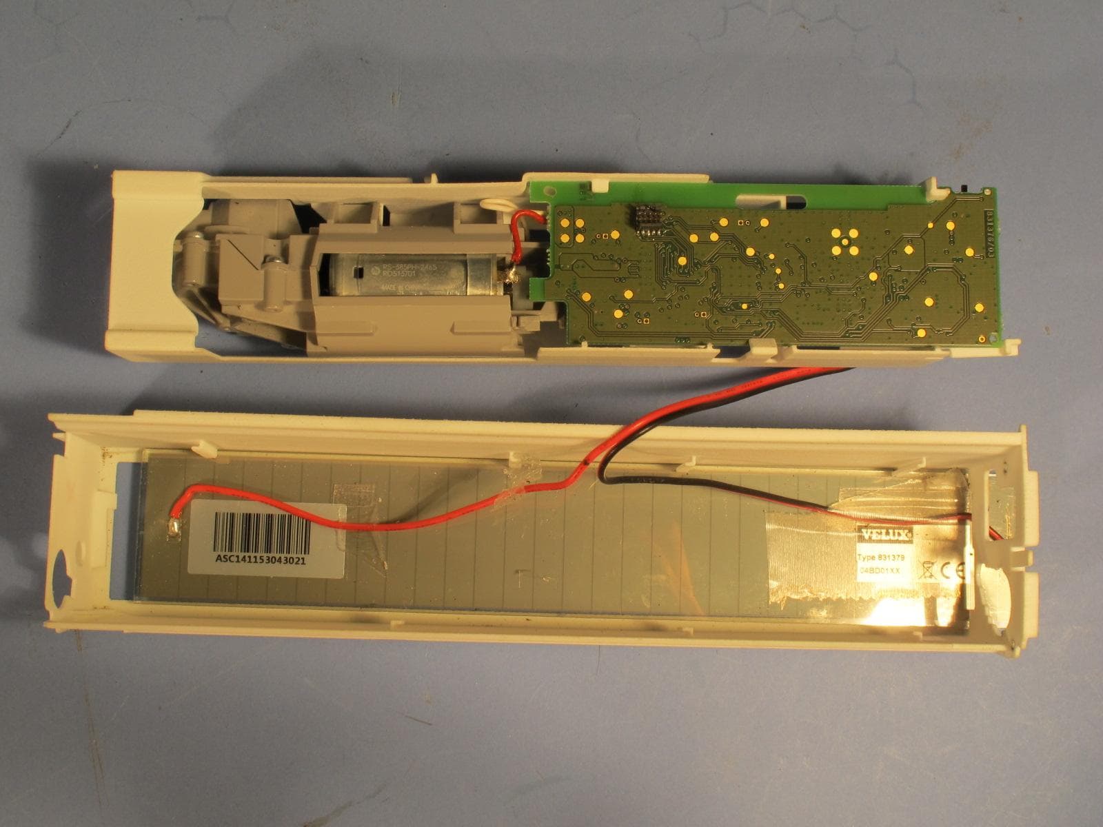
XSG865480
Mar 02, 2015Battery operated Blind
Equipment Class
DTS - Digital Transmission System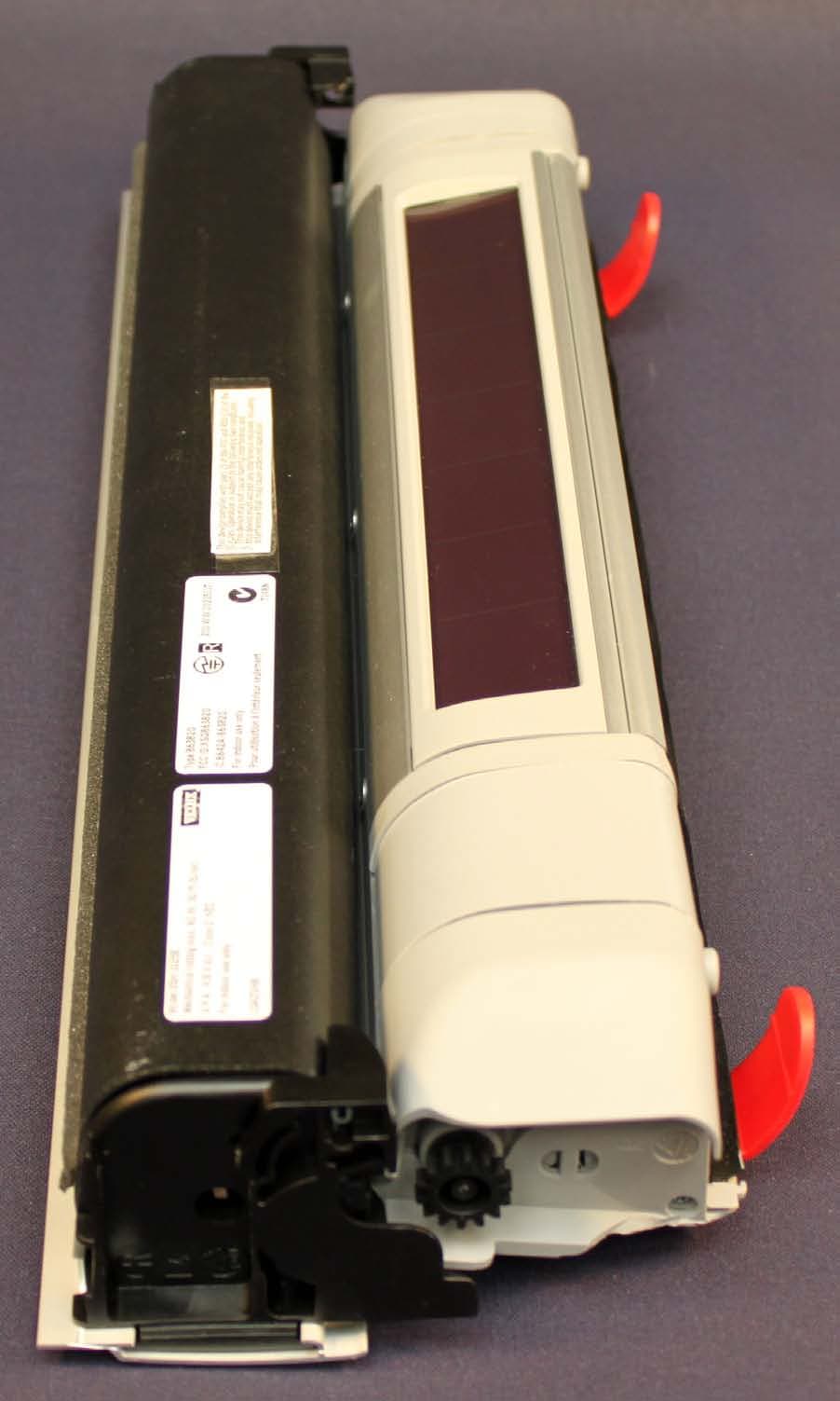
XSG863820
Jun 15, 2010Motor unit for solar/battery powered blinds
Equipment Class
DTS - Digital Transmission System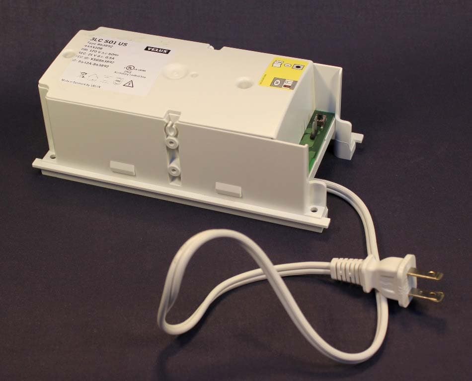
XSG863892
May 14, 2010Control Unit
Equipment Class
DSS - Part 15 Spread Spectrum Transmitter