XSG863820Motor unit for solar/battery powered blinds
VELUX America Inc.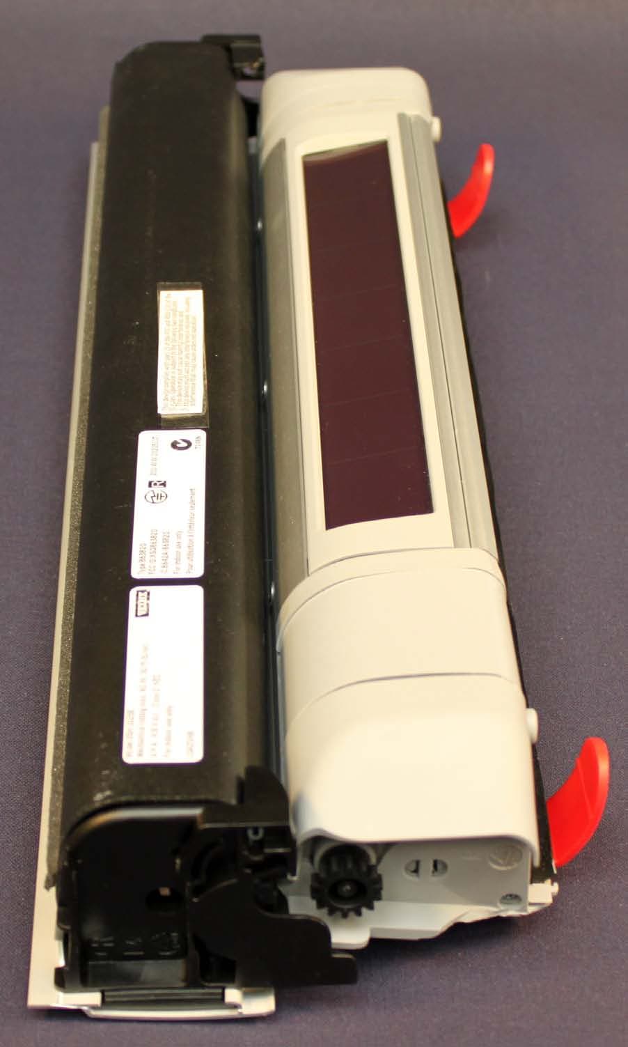
Click to zoom
Application Details
- Equipment Class
- DTS - Digital Transmission System
- Date of Grant
- Jun 15, 2010
- Application Purpose
- Original Equipment
- Date of Application
- Jun 06, 2010
- Equipment Note
- Motor unit for solar/battery powered blinds
- Frequency Range
- 2425.00000000 - 2475.00000000
- Company
- VELUX America Inc.
- Country
- United States
Documents & Files
Document Text
Text extracted from the exhibit documents filed with the FCC. Open a document above to read the original.
Users Manual
Accessory Electric Blinds VAS 452177- 2010-02 DSD/DSH/ RSD/RSH/RSJ VELUX 3 ENGLISH: Important information: Read the instructions in full before installation. To ensure correct function and safe operation of the product, it is important to follow these instructions fully. Keep the instructions for future reference and hand them over to any new user. ESPAÑOL: Información importante: Lea estas instrucciones en su totalidad antes de comenzar. Para garantizar un funcionamiento cor- recto y seguro del producto, es importante seguirlas cuidadosamente. Consérvelas para su uso posterior y entréguelas al consumidor final. FRANÇAIS : Information importante : Lire attentivement la to- talité de la notice avant l'installation. Pour un fonctionnement correct et une manœuvre sûre du produit, il est important de suivre avec attention cette notice. Conserver la notice pour un éventuel besoin ultérieur et le remettre à tout nouvel utilisateur. 4 VELUXVELUX 5 L R ENGLISH: Instructions for control keypad KLI 110 ESPAÑOL: Instrucciones para el teclado de control KLI 110 FRANÇAIS : Instructions pour le bloc numérique KLI 110 VAS 452423-2010-02 KLI 110 452423-2010-02_KLI_110_SKY.indd 128-01-2010 08:20:41 1 5 0 4 0 - 9 0 5 1 5 4 S A V 1 24 35 6 VELUXVELUX 7 L L L R L R LR 2 3 L R L R 5 8 VELUXVELUX 9 LR 4 6 10 VELUXVELUX 11 7 12 VELUXVELUX 13 8 max 5 sec 8 PRG max 2 sec ENGLISH: The diode flashes quickly. ESPAÑOL: El diodo destella rápidamente. FRANÇAIS : Le diode clignote rapidement. ENGLISH: The diode flashes slowly. ESPAÑOL: El diodo destella lentamente. FRANÇAIS : Le diode clignote lentement. max 5 sec max 2 sec 14 VELUXVELUX 15 9 USA: VELUX America Inc. 1-800-88-VELUX CDN: VELUX Canada Inc. 1 800 88-VELUX (888-3589) AUS: VELUX Australia Pty. Ltd 1300 859 856 NZ: VELUX New Zealand Ltd. 09-6344 126 J: VELUX-Japan Ltd. 03(3478)81 41 www.velux.comINSTALLATI o N INSTRUCTI o NS fo R DSD/DSH/RSD/RSH/RSJ. ©2009, 2010 VELUX G R o UP ® VELUX AND THE VELUX L o G o ARE REGISTERED TRADE m ARKS USED UNDER LICENCE B y THE VELUX G R o UP
Users Manual
ENGLISH: Instructions for control keypad KLI 110 ESPAÑOL: Instrucciones para el teclado de control KLI 110 FRANÇAIS : Instructions pour le bloc numérique KLI 110 VAS 452423-2010-07 KLI 110 2 VELUXVELUX 3 ENGLISH: Contents of packaging4-5 Important information and Warnings6-7 Operation12 Set-up and programming14 Security key14 Configuring control keypad KLI 11016-25 - in addition to existing remote control KLR 10016-17 - to control electrical products connected to control unit KLC 50020-21 - in addition to existing control keypad KLI 11024-25 Removing/adding control of electrical products connected to control unit KLC 50028-29 Changing security key32 Resetting35 Installation36-37 ESPANÕL: Contenido del embalaje4-5 Información importante y Advertencias8-9 Funcionamiento12-13 Ajuste y programación 14-15 Código de seguridad15 Configurar el teclado de control KLI 11016-30 - combinado con el mando a distancia KLR 10016-18 - para controlar los productos eléctricos conectados a la unidad de control KLC 50020-22 - combinado con el teclado de control KLI 110 existente24-26 Eliminar/añadir control de productos eléctricos conectados a la unidad de control KLC 50028-30 Cambiar el código de seguridad32-33 Reinicialización35 Instalación36-37 FRANÇAIS : Contenu de l'emballage 4-5 Informations importantes et Avertissement10-11 Fonctionnement12-13 Initialisation et programmation14-15 Code de sécurité15 Configurer le bloc numérique KLI 11016-31 - ajout à une télécommande KLR 100 préexistante 16-19 - pour contrôler des produits électriques connectés à l'unité de contrôle KLC 50020-23 - ajout à un bloc numérique KLI 110 préexistant 24-27 Retirer/ajouter des produits électriques connectés à l'unité de contrôle KLC 500 28-31 Modifier le code de sécurité32-34 Réinitialisation35 Installation36-37 4 VELUXVELUX 5 1 2 3 + + ENGLISH: Contents of packaging 1 : Control keypad 2 : Two batteries (type AAA, 1.5 V) 3 : Screws, wall anchors and double-sided adhesive tape ESPAÑOL: Contenido del embalaje 1 : Teclado de control 2 : Dos baterías (tipo AAA, 1.5 V) 3 : Tornillos, anclajes de pared, cinta adhesiva de dos caras FRANÇAIS : Contenu de l'emballage 1 : Bloc numérique 2 : Deux piles (type AAA, 1,5 V) 3 : Vis, chevilles, adhésif double face 6 VELUXVELUX 7 ENGLISH: ImPORtANt INFORmAtION WARNING – tO REduCE tHE RISK OF SEvERE INjuRy OR dEAtH: Read instructions carefully before installing and operating. Please keep instructions for future reference and hand them over to any new user. Safety • Never let children play with the control keypad. The keypad should be fitted out of reach of children at a minimum height of 5 feet (1.5 m). • The product must not be put into operation until it has been fitted according to these instructions. • Before operating, ensure that the product can be operated without risk of damage to property or injury to people or animals. • This product has been designed for use with genuine VELUX products. • The control keypad is a Class 2 Low Voltage product (3 V d.c.). • FCC ID: XSG863878 and IC ID: 8642A-863878: Remote control (control keypad) This device complies with part 15 of the FCC and RSS-210 of the IC rules. Oper-ation is subject to the following two conditions: (1) This device may not cause harmful interference, and (2) this device must accept any interference received, including interference that may cause undesired operation. • This device has been tested and found to comply with the limits for a Class B digital device, pursuant to part 15 of the FCC Rules. These limits are designed to provide reasonable protection against harmful interference in a residential installation. This device generates, uses and can radiate radio frequency energy and, if not installed and used in accordance with the instructions, may cause harmful interference to radio communications. However, there is no guarantee that interfer- ence will not occur in a particular installation. If this device does cause harmful interference to radio or television reception, which can be determined by turning the device off and on, the user is encouraged to try to correct the interference by one or more of the following measures: FCC Radiation Exposure Statement: • This equipment complies with FCC RF radiation exposure limits set forth for an uncontrolled environment. - Reorient or relocate the receiving antenna. - Increase the separation between the device and receiver. - Connect the device into an outlet on a circuit different from that to which the xreceiver is connected. - Consult the dealer or an experienced radio/TV technician for help. Changes or modifications not expressly approved by the party respon- sible for compliance could void the user’s authority to operate the device. • The term "IC:" before the device certification number only signifies that the Industry Canada technical specifications were met Installation • The control keypad is for indoor use only. • Installation in rooms with a high level of humidity and with hidden wiring must comply with relevant regulations (contact a qualified electrician if necessary). • Before fixing the control keypad to the wall, verify that it can operate the product in question from the proposed position. • The control keypad should be fixed at a position where the product to be operated is within sight. Product • The control keypad has a built-in RF (radio frequency) unit and will not be oper-ative if placed in a metal cabinet. • Electrical products must be disposed of in conformity with all local codes, ordinances, rules and regulations for electronic waste and not with household waste. • Used batteries have to be disposed of in conformity with the relevant environmental regulations and ordinances. • The packaging can be disposed of with usual household waste. 8 VELUXVELUX 9 ESPANÕL: INFORmACIóN ImPORtANtE AdvERtENCIA – PARA RE- duCIR LOS PELIGROS dE LE- SIONES GRAvES y muERtE: Lea estas instrucciones atentamente antes de la instalación y puesta en marcha. Consérve estas instrucci…
Text truncated - open the document above for the full version.
External Photos
External photos
External Photos
Photographs module 20103327300 External PHOTOGRAPH 1: TOP VIEW............................................................................................................................... 2 PHOTOGRAPH 2: BOTTOM VIEW ........................................................................................................................ 3 PHOTOGRAPH 3: ANTENNA VIEW....................................................................................................................... 4 Page: 2 of 4 Report number:20103327300 Photograph 1: Top view Page: 3 of 4 Report number:20103327300 Photograph 2: Bottom view Page: 4 of 4 Report number:20103327300 Photograph 3: Antenna view
ID Label/Location Info
Labels and position info
Internal Photos
Internal photos
Internal Photos
Photographs module 20103327300 Internal PHOTOGRAPH 1: INTERNAL VIEW, NIMH BATTERY REMOVED ............................................................................. 2 PHOTOGRAPH 2: PCB TOP VIEW ....................................................................................................................... 3 PHOTOGRAPH 3: PCB BOTTOM VIEW AND TEMPORARY ANTENNA CONNECTOR .................................................... 4 PHOTOGRAPH 4: NIMH BATTERY ...................................................................................................................... 5 Page: 2 of 5 Report number:20103327300 Photograph 1: Internal view, NiMH battery removed Page: 3 of 5 Report number:20103327300 Photograph 2: PCB top view Page: 4 of 5 Report number:20103327300 Photograph 3: PCB bottom view and temporary antenna connector Page: 5 of 5 Report number:20103327300 Photograph 4: NiMH battery
Test Report
Radio test report 20103327300 based on: - FCC part 15; subpart C; section 15.247 (ed. 10-1-09); FCC part 15, subpart B, section 15.109 (ed. 10-1-09); IC RSS 210, Annex 8 (issue 7) Motor unit for solar/battery powered blinds VELUX 863820 Report number: 20103327300 Contents MAIN MODULE .............................................................................................................................................. 3 1 ...... INTRODUCTION ...................................................................................................................................... 3 2 ...... PRODUCT ............................................................................................................................................... 4 3 ...... TEST SCHEDULE ..................................................................................................................................... 4 4 ...... PRODUCT DOCUMENTATION ................................................................................................................... 5 5 ...... OBSERVATIONS AND COMMENTS ........................................................................................................... 5 6 ...... MODIFICATIONS TO THE SAMPLE ............................................................................................................ 5 7 ...... SUMMARY.............................................................................................................................................. 5 8 ...... CONCLUSIONS ........................................................................................................................................ 6 TEST RESULTS MODULE ............................................................................................................................ 7 1 ...... GENERAL INFORMATION ........................................................................................................................ 7 1.1 Equipment information ..................................................................................................................... 7 1.2 Tested channels ................................................................................................................................. 7 2 ...... EMISSION TESTS ..................................................................................................................................... 8 2.1 Maximum conducted output power................................................................................................... 8 2.2 Minimum 6 dB bandwidth ................................................................................................................ 9 2.3 Tx unwanted emissions attenuation (conducted, 0.030 – 26 GHz) ................................................. 10 2.4 Average factor ................................................................................................................................ 11 2.5 Tx unwanted emissions in the restricted bands ............................................................................... 13 2.6 Rx unwanted emissions (radiated, 0.03 – 1 GHz) ........................................................................... 14 2.7 Rx unwanted emissions (radiated, > 1GHz) .................................................................................... 16 USED TEST EQUIPMENT MODULE ........................................................................................................ 18 CROSS REFERENCE TABLE ..................................................................................................................... 19 This report comprises of three modules. The total number of pages is: 19 Page: 3 of 19 Main module Report number: 20103327300 Main module 1 Introduction This report contains the result of tests performed by: Telefication B.V. Edisonstraat 12a 6902 PK Zevenaar The Netherlands Telefication complies with the accreditation criteria for test laboratories as laid down in ISO/IEC 17025:2005. The accreditation covers the quality system of the laboratory as well as the specific activities as described in the authorized annex bearing the accreditation number L021 and is granted on 30 November 1990 by the Dutch Council For Accreditation (RvA: Raad voor Accreditatie). The contents of this test report, if reproduced, shall be copied in full, unless special consent in writing for reproduction in part is granted by Telefication. Copyright of this test report is reserved to Telefication. Ordering party: Company name : VELUX A/S Address : Baekgaardsvej 40 Zipcode : 6900 City/town : Skjern Country : Denmark Date of order : 20 April 2010 Page: 4 of 19 Main module Report number: 20103327300 2 Product A sample of the following product was submitted for testing: Product description : Motor unit for solar/battery powered blinds Manufacturer : Gaasdal Bygningsindustri A/S Trade mark : VELUX Type designation : 863820 FCC ID : XSG863820 IC ID : 8642A-863820 Hardware version : -- Serial number : -- Firmware release : -- 3 Test schedule Tests are carried out in accordance with the specification detailed in chapter 7 “Summary” of this report. Tests are carried out at the following location: Telefication, Zevenaar The sample of the product is received on: 19 April 2010 Tests are carried out between: 26 April 2010 and 29 April 2010 Page: 5 of 19 Main module Report number: 20103327300 4 Product documentation For production of this report the following product documentation has been used: Description: Date: Identification: RF test modes, version 3.1 09-02-2010 VELUX Manufacturer declarations for RF approval of DSL, version 1.0 19-04-2010 VELUX The above-mentioned documentation will be filed at Telefication for a period of 10 years following the issue of this test report. 5 Observations and comments The EUT was able to transmit or receive continuously on three channels. Furthermore the EUT was able to operate in normal (intermittent)…
Text truncated - open the document above for the full version.
Test Setup Photos
Photographs module 20103327300 Test set up PHOTOGRAPH 1: TEST SETUP RADIATED EMISSIONS (0.03 – 1 GHZ) ................................................................... 2 PHOTOGRAPH 2: TEST SETUP RADIATED EMISSIONS (1 - 18 GHZ) ...................................................................... 3 Page: 2 of 3 Report number:20103327300 Photograph 1: Test setup radiated emissions (0.03 – 1 GHz) Page: 3 of 3 Report number:20103327300 Photograph 2: Test setup radiated emissions (1 - 18 GHz)
Contact Information
Applicant
Jens Aksel Thomsen(Electric safety and EMC/RF Ing.)
Technical Contact
VELUX Accessories A/SJeppe Vestergaard
[email protected]+45 9735 3511
Baekgaardsvej 40 · Skjern · Denmark
Test Firm
Kiwa Nederland B.V.Willem Jong
[email protected]+31 889983621
Technical Specifications
| # | Rule Parts | Frequency Range | Power Output |
|---|---|---|---|
| 1 | 15C | 2.42 GHz - 2.48 GHz | 1.40 mW |
Other Applications from VELUX America Inc.
XSG866062
Sep 17, 2024Blind (battery powered)
Equipment Class
DTS - Digital Transmission System
XSG835403
Aug 04, 2015Remote control
Equipment Class
DTS - Digital Transmission System
XSG865480
Mar 02, 2015Battery operated Blind
Equipment Class
DTS - Digital Transmission System
XSG832876
Feb 13, 2013Battery operated window opener
Equipment Class
DTS - Digital Transmission System
XSG863892
May 14, 2010Control Unit
Equipment Class
DSS - Part 15 Spread Spectrum Transmitter