XV3AVK02BAir Keyboard
Holy Investment Co., Ltd.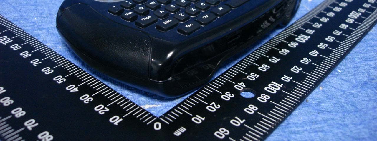
Click to zoom
Application Details
- Equipment Class
- DXX - Part 15 Low Power Communication Device Transmitter
- Date of Grant
- Dec 17, 2009
- Application Purpose
- Original Equipment
- Date of Application
- Dec 17, 2009
- Equipment Note
- Air Keyboard
- Frequency Range
- 2402.00000000 - 2474.00000000
- Company
- Holy Investment Co., Ltd.
- Country
- Taiwan
Documents & Files
Document Text
Text extracted from the exhibit documents filed with the FCC. Open a document above to read the original.
Users Manual
Air Sender User manual 21 1. Installing Air Dongle (Needed Only in PC mode): 2. Installing Batteries 1-1. Using Air Keyboard Air Keyboard does not need any driver or setup. After connecting the Air Dongle to the USB port of the computer, the system will automatically search for Air Keyboard and establish connection. Note: 1. When the batteries have no more power or when they are not used for a long period of time, please replace batteries. 2. Do not mix new and old batteries or different types of batteries. 3. If you intend not to use the product for a long period of time, remove the batteries to avoid damage from leakage and corrosion. 4. Always consider the environmental issues and follow local regulations when disposing batteries. 5. Batteries running out of power should be removed as soon as possible to prevent damage from leakage or corrosion. Fig 3: Replace the lid and push it back until it locks into position. Fig 2: Place 2 batteries (AA/R6) into the compartment. Make sure the positive and negative ends of each battery match with the polarity indicators in the compartment. Fig 1: Open the lid of battery compartment 3. Turn on Power Click the mouse left click button to turn on the power of Air Keyboard. 1-2. Air Keyboard (Multimedia functions apply to Windows operating system) Air Sender User manual 43 Fig. 1 Upper Panel 2. Installing Components of Air Tune and Connecting Air Tune with PC/Notebook 2-1. Installing Components of Air Tune Installing the adapter set into the DC slot of Air Tune. Fig. 2 Installing Air Tune and adapter 1-4. Air Keyboard Troubleshooting If Air Keyboard does not work properly, please follow these trouble- shooting methods. 1. Make sure the batteries are properly installed and the batteries contain enough power. When the remaining power is lower than DC2.2V, the TV indica- tor is on under PC mode,and PC indicator is on under TV mode. Air Keyboard will power off automatically when the power is lower than DC2.0V. You need to replace new batteries. 2. If Air Keyboard does not work properly even with sufficient power, please remove Air Dongle and batteries. Then, replace batteries and reconnect Air Dongle and try gain. 3. The pairing between Air Dongle and Air Keyboard was completed before shipment. If the above steps does not solve your issue, it might be that the pairing was lost,perform the following pairing steps again: 1) Install batteries in Air Keyboard and connect Air Dongle to the computer. 2) Bring Air Keyboard next to Air Dongle. Press and hold the button on Air Dongle. Press the “POWER” and “mouse right click” buttons at the same time. Air Keyboard will search for Air Dongle and the green LED indicator will be blinking. Hold down the button on Air Dongle until the blue light on Air Dongle is no longer blinking and stays on and the green indicator on Air Keyboard stays on for 2 seconds. The pairing is now completed and you can start using Air Keyboard. If Air Keyboard does not work correctly after the above steps are performed 3 times,please consult your dealer. ¾ ¾ LED indicator for pairing Pairing button 1-3. Air Dongle 1 2 1 2
Attestation Statements
R&D Print date 09/07/13 Pre Jul, 2009 3216 Ceramic Chip Antenna (PIFA Mode) for Bluetooth/WLan Application CAN4311 712 1X 245 3K Tommy Chen Page 1 sheet 190-1 A4 Willing Chang Oscar Lu Yageo Taiwan / High Frequency Ceramic Department Jul. 2009. ANTENNA PRODUCTS 3216 Ceramic Chip Antenna in PIFA Mode for Bluetooth/WLan Application Preliminary R&D Print date 09/07/13 Pre Jul, 2009 3216 Ceramic Chip Antenna (PIFA Mode) for Bluetooth/WLan Application CAN4311 712 1X 245 3K Tommy Chen Page 2 sheet 190-2 A4 Willing Chang Oscar Lu Yageo Taiwan / High Frequency Ceramic Department 3216 Ceramic Chip Antenna for Bluetooth/WLAN Application Product Specification Quick Reference Data Centre Frequency 2.45 GHz Bandwidth 2.4 ~ 2.484GHz Polarization Linear Azimuth Beamwidth Omni-directional Peak Gain 2.84 dBi Impedance 50Ω Operating Temperature -25~85°C Termination Ni / Sn (Environmentally-Friendly Leadless) Resistance to soldering heats 260°C , 10sec. Maximum Power 1W Special Environmental Concerns- Green Products Design: The foil making process is using environmentally-friendly aqueous solvent technology. Termination is lead free (Pb free) and packing materials can be re-cycled R&D Print date 09/07/13 Pre Jul, 2009 3216 Ceramic Chip Antenna (PIFA Mode) for Bluetooth/WLan Application CAN4311 712 1X 245 3K Tommy Chen Page 3 sheet 190-3 A4 Willing Chang Oscar Lu Yageo Taiwan / High Frequency Ceramic Department 1. Mechanical Data (3.2 x 1.6x 1.2 mm³) 1.2±0.1 3.2±0.1 1.6±0.1 Unit: mm R&D Print date 09/07/13 Pre Jul, 2009 3216 Ceramic Chip Antenna (PIFA Mode) for Bluetooth/WLan Application CAN4311 712 1X 245 3K Tommy Chen Page 4 sheet 190-4 A4 Willing Chang Oscar Lu Yageo Taiwan / High Frequency Ceramic Department 2. Evaluation Board Dimension and Outlook ■IllustrationofEvaluationBoard Matching Circuit Ground contact Feed contact 50 ΩFeed Line 40.0 90.0 Ground via hole Copper Unit: mm ■ Suggested Matching Circuit : Feeding 0.82 pF 3216PIFAantenna 2.2 pF R&D Print date 09/07/13 Pre Jul, 2009 3216 Ceramic Chip Antenna (PIFA Mode) for Bluetooth/WLan Application CAN4311 712 1X 245 3K Tommy Chen Page 5 sheet 190-5 A4 Willing Chang Oscar Lu Yageo Taiwan / High Frequency Ceramic Department ■ClearanceDefinition: ( Size = 6.0 * 4.0 mm ) 0.64 0.64 6.0 4.0 1.6 1.25 1.25 4.0 0.32 0.40 Unit: mm ■ Soldering Pads Dimension and Footprint : Tol : ±0.2 Unit : mm 1.25 1.25 4.0 1.6 0.64 0.32 R&D Print date 09/07/13 Pre Jul, 2009 3216 Ceramic Chip Antenna (PIFA Mode) for Bluetooth/WLan Application CAN4311 712 1X 245 3K Tommy Chen Page 6 sheet 190-6 A4 Willing Chang Oscar Lu Yageo Taiwan / High Frequency Ceramic Department 3. Measured S-parameter R&D Print date 09/07/13 Pre Jul, 2009 3216 Ceramic Chip Antenna (PIFA Mode) for Bluetooth/WLan Application CAN4311 712 1X 245 3K Tommy Chen Page 7 sheet 190-7 A4 Willing Chang Oscar Lu Yageo Taiwan / High Frequency Ceramic Department 4.The Definition of X-Y-Z Plane Y Z X R&D Print date 09/07/13 Pre Jul, 2009 3216 Ceramic Chip Antenna (PIFA Mode) for Bluetooth/WLan Application CAN4311 712 1X 245 3K Tommy Chen Page 8 sheet 190-8 A4 Willing Chang Oscar Lu Yageo Taiwan / High Frequency Ceramic Department 5. The Environment of Antenna Radiation Pattern Anechoic Chamber Dimension=10(m) × 6(m) × 6(m) R&D Print date 09/07/13 Pre Jul, 2009 3216 Ceramic Chip Antenna (PIFA Mode) for Bluetooth/WLan Application CAN4311 712 1X 245 3K Tommy Chen Page 9 sheet 190-9 A4 Willing Chang Oscar Lu Yageo Taiwan / High Frequency Ceramic Department 6. Radiation Pattern R&D Print date 09/07/13 Pre Jul, 2009 3216 Ceramic Chip Antenna (PIFA Mode) for Bluetooth/WLan Application CAN4311 712 1X 245 3K Tommy Chen Page 10 sheet 190-10 A4 Willing Chang Oscar Lu Yageo Taiwan / High Frequency Ceramic Department 7. Reliability Test IEC 384-10/ CECC 32 100 CLAUSE IEC 60068-2 TEST METHO D TEST PROCEDURE REQUIREMENTS 4.4 Mounting The antenna can be mounted on printed- circuit boards or ceramic substrates by applying wave soldering, reflow soldering (including vapour phase soldering) or conductive adhesive No visible damage 4.5 Visual inspection and dimension check Any applicable method using × 10 magnification In accordance with specification (chip off 4mm) 4.6.1 Antenna Central Frequency at 20 o C Standard test board in page 4 4.8 Adhesion A force of 3 N applied for 10 s to the line joining the terminations and in a plane parallel to the substrate No visible damage Bond strength of plating on end face Mounted in accordance with CECC 32 100, paragraph 4.4 No visible damage 4.9 Conditions: bending 0.5 mm at a rate of 1mm/s, radius jig. 340 mm, 2mm warp on FR4 board of 90 mm length No visible damage R&D Print date 09/07/13 Pre Jul, 2009 3216 Ceramic Chip Antenna (PIFA Mode) for Bluetooth/WLan Application CAN4311 712 1X 245 3K Tommy Chen Page 11 sheet 190-11 A4 Willing Chang Oscar Lu Yageo Taiwan / High Frequency Ceramic Department IEC 384-10/ CECC 32 100 CLAUSE IEC 60068-2 TEST METHO D TEST PROCEDURE REQUIREMENTS 4.10 20(Tb) Resistance to soldering heat 260 ± 5 °C for 10 ± 0.5 s in a static solder bath Satisfy the original electrical specification after soldering. Resistance to leaching 260 ± 5 °C for 30 ± 1 s in a static solder bath Using visual enlargement of × 10, dissolution of the termination shall not exceed 10% 4.11 20(Ta) Solderability Zero hour test, and test after storage (20 to 24 months) in original atmosphere; un-mounted chips completely immersed for 2 ± 0.5 s in 235 ± 5°C. The termination must be well tinned, at least 75% is well tinned at termination 4.12 4(Na) Rapid change of temperature -25 °C (30 minutes) to +85 °C (30 minutes); 100 cycles No visible damage Central Freq. Change ± 6% 4.14 3(Ca) Damp heat 500 ± 12 hours at 60 °C; 90 to 95 % RH No visible damage 2 hours recovery Central Freq. Change ± 6% 4.15 Endurance 500 ± 12 hours at 85 °C; No visible damage 2 hours recovery Central Freq. Change ± 6% R&D Print date 09/07/13 Pre Jul, 2009 3216 Ceramic Chip Antenna (PIFA Mode) for Bluetooth/WLan Application CAN4311…
Text truncated - open the document above for the full version.
External Photos
Compliance Certification Services Inc. Report No.:91109401 External Photo ( Model : AVK-02b )
ID Label/Location Info
AVK-02b Diagram Label Location FCC ID: XV3AVK01
Internal Photos
Compliance Certification Services Inc. Report No.:91109401 Internal Photo Compliance Certification Services Inc. Report No.:91109401
RF Exposure Info
!!Compliance Certification Services Inc.!! Report No.Κ91109401-RP1 FCC ID˖XV3AVK02B Date of Issue: November 28, 2009! ! 8.3 MAXIMUM PERMISSIBLE EXPOSURE According to FCC 1.1310 : The criteria listed in the following table shall be used to evaluate theʳ environment impact of human exposure to radio frequency (RF) radiation as specified in 1.1307(b)LIMITS FOR MAXIMUM PERMISSIBLE EXPOSURE (MPE) Frequency Range (MHz) Electric Field Strength (V/m) Magnetic Field Strength (A/m) Power Density (mW/cm 2 ) Average Time (A) Limits for Occupational / Control Exposures 300-1,500 -- -- F/300 6 1,500-100,000 -- -- 5 6 (B) Limits for General Population / Uncontrol Exposures 300-1,500 -- -- F/1500 6 1,500-100,000 -- -- 1 30 CALCULATIONS Given d GP E uu 30 & 3770 2 E S Where E = Field strength in Volts / meter P = Power in Watts G = Numeric antenna gain d = Distance in meters S = Power density in milliwatts / square centimeter Combining equations and re-arranging the terms to express the distance as a function of the remaining variables yields: 2 3770 30 d GP S uu Changing to units of mW and cm, using: P (mW) = P (W) / 1000 and d (cm) = d(m) / 100 Yields 2 2 0796.0 100/3770 1000/30 d GP d GP S u u u uu Where d = Distance in cm P = Power in mW G = Numeric antenna gain S = Power density in mW / cm 2 !!Compliance Certification Services Inc.!! Report No.Κ91109401-RP1 FCC ID˖XV3AVK02B Date of Issue: November 28, 2009! ! 31! LIMIT 60/f(GHz)mW ! TEST RESULTS No non-compliance noted And according to KDB447498 Section 1) c) Unless excluded by specific FCC test procedures, portable devices with output power > 60/f(GHz)mW shall include SAR data for equipment approval. Details please refer to FCC Part 2 and attached KDB447498. Please note the low power threshold is based upon average output power. If the average output power is below 60/f(GHz), then SAR evaluation is not required. In addition, since this device is a Bluetooth device, you may use source-based averaging duty cycle to adjust the average power. After the adjustment, if the average power is greater than 60/f(GHz), then SAR is required. 60/f(GHz)mW f(the highest frequency) f=2.462GHz 60/2.462=24.37mW=((log24.37)*10)dBm=13.8686dBm Mode Output Power (dBm) Limit (dBm) Result CH Low Mode -13.53 13.8686 Compliance CH Mid Mode -12.90 13.8686 Compliance CH High Mode -12.23 13.8686 Compliance
Test Report
Compliance Certification Services Inc. Report No.:91109401-RP1 FCC ID:XV3AVK02B Date of Issue: November 28, 2009 FCC 47 CFR PART 15 SUBPART C AND ANSI C63.4: 2003 TEST REPORT For Air Keyboard Model : AVK-02b Brand : Issued for Holy Investment Co., Ltd. 1F., No.2, Lane 25, Yong-an 2nd St., Yongkang City, Tainan County 710, Taiwan Issued by Compliance Certification Services Inc. Tainan Lab. No. 8, Jiu Cheng Ling, Jiaokeng Village,Sinhua Township, Tainan Hsien 712, Taiwan R.O.C. TEL: 886-6-580-2201 FAX: 886-6-580-2202 Note: This report shall not be reproduced except in full, without the written approval of Compliance Certification Services Inc. Ltd. This document may be altered or revised by Compliance Certification Services Inc. personnel only, and shall be noted in the revision section of the document Total Page: 68 Compliance Certification Services Inc. Report No.:91109401-RP1 FCC ID:XV3AVK02B Date of Issue: November 28, 2009 REVISION HISTORY Rev. Issue Date Revisions Effect Page Revised By 00 November 28, 2009 Initial Issue ALL Leah Peng Compliance Certification Services Inc. Report No.:91109401-RP1 FCC ID:XV3AVK02B Date of Issue: November 28, 2009 TABLE OF CONTENTS 1. TEST REPORT CERTIFICATION............................................................................................ 4 2. EUT DESCRIPTION .................................................................................................................... 5 2.1 DESCRIPTION OF EUT & POWER ......................................................................................................5 3. DESCRIPTION OF TEST MODES ............................................................................................ 6 4. TEST METHODOLOGY .............................................................................................................7 5. FACILITIES AND ACCREDITATIONS................................................................................... 7 5.1 FACILITIES.............................................................................................................................................7 5.2 EQUIPMENT ...........................................................................................................................................7 5.3 LABORATORY ACCREDITATIONS LISTINGS ................................................................................7 5.4 TABLE OF ACCREDITATIONS AND LISTINGS ...............................................................................8 6. CALIBRATION AND UNCERTAINTY .................................................................................... 9 6.1 MEASURING INSTRUMENT CALIBRATION ...................................................................................9 6.2 MEASUREMENT UNCERTAINTY ......................................................................................................9 7. SETUP OF EQUIPMENT UNDER TEST.................................................................................. 10 7.1 SETUP CONFIGURATION OF EUT .....................................................................................................10 7.2 SUPPORT EQUIPMENT ........................................................................................................................10 8. APPLICABLE LIMITS AND TEST RESULTS ........................................................................ 11 8.1 6DB BANDWIDTH.................................................................................................................................11 8.2 MAXIMUM PEAK OUTPUT POWER ..................................................................................................15 8.3 MAXIMUM PERMISSIBLE EXPOSURE .............................................................................................19 8.4 POWER SPECTRAL DENSITY .............................................................................................................21 8.5 CONDUCTED SPURIOUS EMISSION .................................................................................................24 8.6 RADIATED EMISSIONS .......................................................................................................................28 8.7 POWERLINE CONDUCTED EMISSIONS ...........................................................................................63 9. ANTENNA REQUIREMENT...................................................................................................... 65 9.1 STANDARD APPLICABLE ...................................................................................................................65 9.2 ANTENNA CONNECTED CONSTRUCTION......................................................................................65 APPENDIX SETUP PHOTOS ......................................................................................................... 66 Compliance Certification Services Inc. Report No.:91109401-RP1 FCC ID:XV3AVK02B Date of Issue: November 28, 2009 1. TEST REPORT CERTIFICATION Applicant : Holy Investment Co., Ltd. Address : 1F., No.2, Lane 25, Yong-an 2nd St., Yongkang City, Tainan County 710, Taiwan Manufacture : Jow Tong Technology CO., LTD. Address : 46, Lane 337, Chung Cheng Rd., Yung Kang City, Tainan County 710, Taiwan, R.O.C. Equipment Under Test : Air Keyboard Model Number : AVK-02b Brand Name : Date of Test : November 10, 2009 ~ November 17, 2009 APPLICABLE STANDARD STANDARD TEST RESULT FCC Part 15 Subpart C : 2004 AND ANSI C63.4 : 2003 No non-compliance noted Approved by: Reviewed by: Jeter Wu Eric Yang Section Manager Senior Engineer Compliance Certification Services Inc. Compliance Certification Services Inc. Compliance Certification Services Inc. Report No.:91109401-RP1 FCC ID:XV3AVK02B Date of Issue: November 28, 2009 2. EUT DESCRIPTION 2.1 DESCRIPTION OF EUT & POWER Product Name Air Keyboard Model Number AVK-02b Brand Name Frequency Range TX Mode : 2402MHz~2474MHz Transmit Power TX Mode : -12.23dBm(0.059841 mW) Channel Spacing TX …
Text truncated - open the document above for the full version.
Test Setup Photos
!!Compliance Certification Services Inc.!! Report No.Κ91109401-RP1 FCC ID˖XV3AVK02B Date of Issue: November 28, 2009! Qbhf!77! APPENDIX SETUP PHOTOS RADIATED EMISSION MEASUREMENT SETUP ! ! ! ! ! !!Compliance Certification Services Inc.!! Report No.Κ91109401-RP1 FCC ID˖XV3AVK02B Date of Issue: November 28, 2009! Qbhf!78! RADIATED RF MEASUREMENT SETUP ! !!Compliance Certification Services Inc.!! Report No.Κ91109401-RP1 FCC ID˖XV3AVK02B Date of Issue: November 28, 2009! Qbhf!79! ! ! CONDUCTED PHOTO !! ! End of report
Contact Information
Applicant
Ethan Chen(Manager)
Technical Contact
Compliance Certification Services Inc.Landy Sung
No. 8, Jiu Cheng Ling, Jiaokeng Village, · Tainan · Taiwan
Test Firm
Compliance Certification Services Inc.Daphne Liang
Technical Specifications
| # | Rule Parts | Frequency Range | Power Output |
|---|---|---|---|
| 1 | 15C | 2.40 GHz - 2.47 GHz | 59.80 mW |
Other Applications from Holy Investment Co., Ltd.
XV3AD22
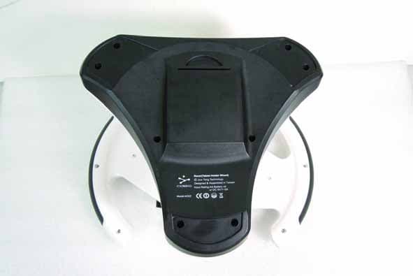
Oct 29, 2012Racer(Tablet Holder Wheel)
Equipment Class
DSS - Part 15 Spread Spectrum Transmitter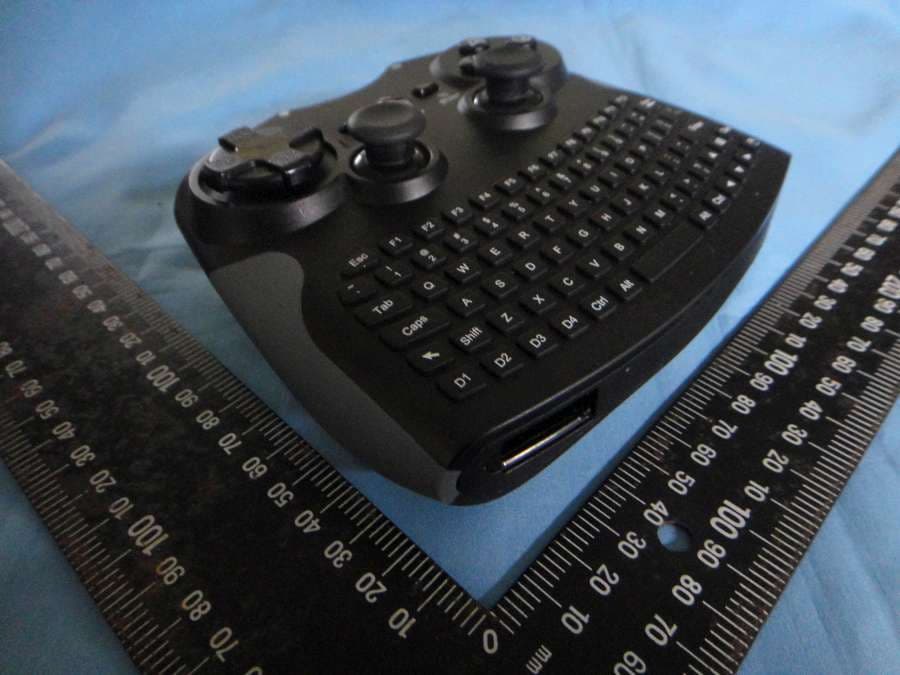
XV3AK10
Mar 25, 2012BASIC AIR KEYBOARD CONQUEROR
Equipment Class
DXX - Part 15 Low Power Communication Device Transmitter
XV3AB03B
Dec 27, 2011CIDEKO SIMPLE BOX ADVANCED
Equipment Class
DTS - Digital Transmission System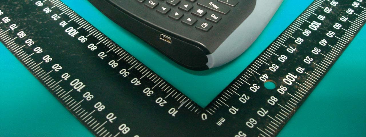
XV3AK08B
Oct 26, 2010Air Keyboard Conqueror
Equipment Class
DXX - Part 15 Low Power Communication Device Transmitter
XV3UD08B
Oct 26, 2010Air Dongle
Equipment Class
DXX - Part 15 Low Power Communication Device Transmitter