XV6AIDAAida Thermostat and Aida Controller
Telkonet, Inc.
Click to zoom
Application Details
- Equipment Class
- DTS - Digital Transmission System
- Date of Grant
- May 04, 2023
- Application Purpose
- Original Equipment
- Date of Application
- May 04, 2023
- Equipment Note
- Aida Thermostat and Aida Controller
- Frequency Range
- 2405.00000000 - 2480.00000000
- Company
- Telkonet, Inc.
- Country
- United States
Documents & Files
Document Text
Text extracted from the exhibit documents filed with the FCC. Open a document above to read the original.
Users Manual
Aida Installation, Operation, & Maintenance Guide (IOM) CONTENTS Updates3 Chapter 1: Overview1 Intended Audience1 What is Aida?1 What Can the Telkonet Thermostat Do?1 Sample Use Cases1 Maximum Number of Associated Devices2 How to Get Support2 FCC Compliance Statement2 Chapter 2: Installation4 Voltage Options-Summary4 Required Equipment5 Installation - High Voltage (Non-Class 2)9 Installation - Low Voltage (Class 2)14 Chapter 3: Add Ons17 About Wiring the Aida17 NTC Probe17 CT Inputs17 Chapter 4: User Interface19 Chapter 5: Appendices20 Proportional Valve Control; Analog Output20 JBox Mounting Options21 2 AidaIOM UPDATES Revision 4: add FCC RF Exposure statement and Canadian RF Exposure Statement 3 AidaIOM Chapter 1: Overview INTENDED AUDIENCE These instructions are intended for: l Installers who are either Telkonet certified installers or have completed a series of Telkonet micro-training courses (contact your Telkonet Project Manager for details) l Facilities engineers who will maintain Telkonet devices WHAT IS AIDA? Aida thermostats are like traditional thermostats in that they are wired to the HVAC system. They feature six relays, and the occupants interact with them to adjust room climate. Aida thermostats are different than traditional thermostats in that they are “smart”. Aida thermostats feature occupancy sensors, so it is important to install them in the location where they can best sense occupancy WHAT CAN THE TELKONET THERMOSTAT DO? The Telkonet thermostat will automatically learn and adapt to the heating and cool- ing patterns of each room. For example, a room on the east side of a building will receive direct sunlight in the morning and will either need less heating or more cooling. However, as the day pro- gresses, the room will need more heating or less cooling as it moves into the shade. A Telkonet thermostat will continually monitor the room, learn its patterns, and adjust its heating and cooling profiles accordingly. Telkonet thermostats also learn and adapt to occupant schedules. When a room is unoccupied, the thermostat will enter an energy-saving mode, allowing the room to drift away from the desired set point. During this drift period, the thermostat will oper- ate the HVAC unit less often, reducing energy costs. When the room becomes occu- pied again, the Telkonet Recovery Time™ technology built into each thermostat will return the room to the setpoint without the occupant noticing. SAMPLE USE CASES Telkonet thermostats are available in several possible configurations, to address spe- cific requirements of multiple applications including hotels, classrooms, university housing, military residence halls, senior living facilities, multi-dwelling units, and a wide variety of other commercial and industrial spaces. Chapter1: Overview1 AidaIOM MAXIMUM NUMBER OF ASSOCIATED DEVICES Aida can accept associations with up to 32 total Telkonet and other compatible wire- less devices, such as occupancy sensors and door contacts. HOW TO GET SUPPORT DURING INSTALLATION Contact your dedicated Telkonet Project Manager if you have any installation ques- tions. AFTER INSTALLATION Contact the Telkonet Support Center at [email protected], (414) 302-2203, or the phone number you were provided at installation, based on your support subscription plan. FCC COMPLIANCE STATEMENT This equipment has been tested and found to comply with the limits for a Class B digital device, pursuant to Part 15 of the FCC Rules. These limits are designed to provide reasonable protection against harmful interference in a residential install- ation. This equipment generates, uses and can radiate radio frequency energy and if not installed and used in accordance with the instructions, may cause harmful inter- ference to radio communications. However, there is no guarantee that interference will not occur in a particular installation. If this equipment does cause harmful inter- ference to radio or television reception, which can be determined by turning the equipment off and on, the user is encouraged to try to correct the interference by one or more of the following measures: * Reorient or relocate the receiving antenna. * Increase the separation between the equipment and receiver. * Connect the equipment into an outlet on a circuit different from that to which the receiver is connected. * Consult the dealer or an experienced radio/TV technician for help. Operation with non-approved equipment is likely to result in interference to radio and TV reception. The user is cautioned that changes and modifications made to the equipment without the approval of the manufacturer could void the user's authority to operate this equipment. FCC RF Exposure Statement: To comply with FCC RF exposure compliance require- ments, the device must be installed to provide a separation distance of at least 20 cm from all persons. Chapter1: Overview2 AidaIOM CANADIAN COMPLIANCE STATEMENT This device contains licence-exempt transmitter(s)/receiver(s) that comply with Innov- ation, Science and Economic Development Canada’s licence-exempt RSS(s). Oper- ation is subject to the following two conditions: (1) This device may not cause interference. (2) This device must accept any interference, including interference that may cause undesired operation of the device. Canadian RF Exposure Statement: This equipment complies with Canada radiation exposure limits set forth for an uncontrolled environment. This equipment should be installed and operated with minimum distance 20 cm from the radiator and your body. L’émetteur/récepteur exempt de licence contenu dans le présent appareil est con- forme aux CNR d’Innovation, Sciences et Développement économique Canada applic- ables aux appareils radio exempts de licence. L’exploitation est autorisée aux deux conditions suivantes 1) L’appareil ne doit pas produire de brouillage; 2) L’appareil doit accepter tout brouillage radioélectrique subi, même si le brouillage est susceptible d’en compromettre le fonc…
Text truncated - open the document above for the full version.
Users Manual
ES Controller Installation, Operation, & Maintenance Guide (IOM) CONTENTS Updates2 Chapter 1: Overview3 Intended Audience3 What is es Controller?3 What Can the Telkonet Thermostat Do?3 Sample Use Cases3 How to Get Support4 FCC Compliance Statement4 Chapter 2: Installation6 Voltage Options-Summary6 Required Equipment7 Installation - High Voltage (Non-Class 2)7 Installation - Low Voltage (Class 2)12 Chapter 3: Add Ons15 About Wiring the ES Controller15 NTC Probe15 CT Inputs15 Chapter 4: Appendix17 UPDATES Revision 3: add FCC RF Exposure statement and Canadian RF Exposure Statement 2 ESControllerIOM Chapter 1: Overview INTENDED AUDIENCE These instructions are intended for: l Installers who are either Telkonet certified installers or have completed a series of Telkonet micro-training courses (contact your Telkonet Project Manager for details) l Facilities engineers who will maintain Telkonet devices WHAT IS ES CONTROLLER? The ES Controller is an HVAC controller. You will wire it to the HVAC system. It does not have a user screen or any buttons for an occupant to press. The screen and the buttons are on a separate user interface. The controller and user interface com- municate with each other wirelessly. Telkonet thermostats are “smart”. They are typ- ically part of a larger energy management network. We call our thermostats the “brain of the room” because they gather data about the room (like occupancy status) and send it to a central location (usually Rhapsody). WHAT CAN THE TELKONET THERMOSTAT DO? The Telkonet thermostat will automatically learn and adapt to the heating and cool- ing patterns of each room. For example, a room on the east side of a building will receive direct sunlight in the morning and will either need less heating or more cooling. However, as the day pro- gresses, the room will need more heating or less cooling as it moves into the shade. A Telkonet thermostat will continually monitor the room, learn its patterns, and adjust its heating and cooling profiles accordingly. Telkonet thermostats also learn and adapt to occupant schedules. When a room is unoccupied, the thermostat will enter an energy-saving mode, allowing the room to drift away from the desired set point. During this drift period, the thermostat will oper- ate the HVAC unit less often, reducing energy costs. When the room becomes occu- pied again, the Telkonet Recovery Time™ technology built into each thermostat will return the room to the setpoint without the occupant noticing. SAMPLE USE CASES Telkonet thermostats are available in several possible configurations, to address spe- cific requirements of multiple applications including hotels, classrooms, university housing, military residence halls, senior living facilities, multi-dwelling units, and a wide variety of other commercial and industrial spaces. Chapter1: Overview3 ESControllerIOM HOW TO GET SUPPORT DURING INSTALLATION Contact your dedicated Telkonet Project Manager if you have any installation ques- tions. AFTER INSTALLATION Contact the Telkonet Support Center at [email protected], (414) 302-2203, or the phone number you were provided at installation, based on your support subscription plan. FCC COMPLIANCE STATEMENT This equipment has been tested and found to comply with the limits for a Class B digital device, pursuant to Part 15 of the FCC Rules. These limits are designed to provide reasonable protection against harmful interference in a residential install- ation. This equipment generates, uses and can radiate radio frequency energy and if not installed and used in accordance with the instructions, may cause harmful inter- ference to radio communications. However, there is no guarantee that interference will not occur in a particular installation. If this equipment does cause harmful inter- ference to radio or television reception, which can be determined by turning the equipment off and on, the user is encouraged to try to correct the interference by one or more of the following measures: * Reorient or relocate the receiving antenna. * Increase the separation between the equipment and receiver. * Connect the equipment into an outlet on a circuit different from that to which the receiver is connected. * Consult the dealer or an experienced radio/TV technician for help. Operation with non-approved equipment is likely to result in interference to radio and TV reception. The user is cautioned that changes and modifications made to the equipment without the approval of the manufacturer could void the user's authority to operate this equipment. FCC RF Exposure Statement: To comply with FCC RF exposure compliance require- ments, the device must be installed to provide a separation distance of at least 20 cm from all persons. CANADIAN COMPLIANCE STATEMENT This device contains licence-exempt transmitter(s)/receiver(s) that comply with Innov- ation, Science and Economic Development Canada’s licence-exempt RSS(s). Oper- ation is subject to the following two conditions: (1) This device may not cause interference. Chapter1: Overview4 ESControllerIOM (2) This device must accept any interference, including interference that may cause undesired operation of the device. Canadian RF Exposure Statement: This equipment complies with Canada radiation exposure limits set forth for an uncontrolled environment. This equipment should be installed and operated with minimum distance 20 cm from the radiator and your body. L’émetteur/récepteur exempt de licence contenu dans le présent appareil est con- forme aux CNR d’Innovation, Sciences et Développement économique Canada applic- ables aux appareils radio exempts de licence. L’exploitation est autorisée aux deux conditions suivantes 1) L’appareil ne doit pas produire de brouillage; 2) L’appareil doit accepter tout brouillage radioélectrique subi, même si le brouillage est susceptible d’en compromettre le fonctionnement. Declaration d'exposition aux radiations: Cet equipement est conforme aux !imites d'exposition aux r…
Text truncated - open the document above for the full version.
Attestation Statements
Telkonet Inc. 20800 Swenson Drive, Suite 175, Waukesha, WI 53186 p: 414.302.2299 | f: 414.800.4352 www.telkonet.com February 23, 2023 CETCB 114 Olinda Drive Brea, CA 92823 Gentlemen: This is a letter of authorization to accept Compatible Electronics, Inc., specifically including the employees of Compatible Electronics, as an Agent for Telkonet Inc., 20800 Swenson Dr. Suite 175, Waukesha, WI 53186, for a period of one year, to sign applications before the Commission on our behalf, to make representations to you on our behalf, and to receive and exchange data between our company and the Commission in connection with certification of the following Telkonet product: Smart Thermostat under FCC Docket Number 20780 and General Docket Number 80-284 pursuant to Part l5 of FCC Rules and Regulations. Please also accept this letter as an attestation that neither Telkonet nor any of its officers, directors, or persons holding 5% or more of the outstanding stock or shares, voting or non-voting, have been denied federal benefits under section 5301 of the Anti-Drug-Abuse act of 1988,21 U.S.C. 853(a). In addition, Telkonet will notify the Federal Communications Commission if, at any time, the situation changes causing Telkonet to be denied federal benefits. If you have any further questions or need additional information, please feel free to give me a call at 414-302-2205. Sincerely, Jeffrey Sobieski CTO
Attestation Statements
Telkonet Inc. 20800 Swenson Drive, Suite 175, Waukesha, WI 53186 p: 414.302.2299 | f: 414.800.4352 www.telkonet.com February 23, 2023 Compatible Electronics TCB 114 Olinda Drive Brea, California 92823 Subject: TCB application submittal Gentlemen: We, Telkonet Inc., would like to declare that the application being submitted for the device with FCC ID: XV6AIDA, has not been submitted to another TCB or FCC for certification. If you have any questions, please do not hesitate to contact us at 414-302-2299. Sincerely, Jeffrey Sobieski CTO
Attestation Statements
Telkonet Inc. 20800 Swenson Drive, Suite 175, Waukesha, WI 53186 p: 414.302.2299 | f: 414.800.4352 www.telkonet.com April 20, 2023 Federal Communications Commission Authorization and Evaluation Division 7435 Oakland Mills Road Columbia, Maryland 21046 FCC ID: XV6AIDA Subject: Attestation Statement pursuant to Part 2.911 (d)(7) Telkonet, Inc. “applicant”, as of the date of this filing, will also serve as the U.S. agent for service of process for the above reference FCC ID as required in Part 2.911(d)(7). The applicant acknowledges that they will maintain an agent for service of process for no less than one year after the grantee has terminated all marketing and importation or the conclusion of any Commission-related proceeding involving the equipment. The applicant further acknowledges their responsibility to inform the FCC whenever the agent information changes. US Agent Company Name/Applicant: Telkonet, Inc. Contact Name: Jeffrey Sobieski Address: 20800 Swenson Drive, Suite 175, Waukesha, WI 53186 Telephone Number: (414) 258-8307 E-Mail: [email protected] FRN: 0018901058 Sincerely, Telkonet, Inc. Jeffrey Sobieski CTO
Attestation Statements
Telkonet Inc. 20800 Swenson Drive, Suite 175, Waukesha, WI 53186 p: 414.302.2299 | f: 414.800.4352 www.telkonet.com February 23, 2023 Federal Communications Commission Authorization and Evaluation Division 7435 Oakland Mills Road Columbia, Maryland 21046 FCC ID: XV6AIDA Subject: Attestation Statements pursuant to Part 2.911 (d)(5)(i) Telkonet, Inc., 20800 Swenson Dr, Suite 175, Waukesha, WI certifies that the equipment for which authorization is sought is not “covered” equipment prohibited from receiving an equipment authorization pursuant to section 2.903 of the FCC rules and according to FCC 22-84 and KDB 986446. Sincerely, Jeffrey Sobieski CTO
Attestation Statements
Telkonet Inc. 20800 Swenson Drive, Suite 175, Waukesha, WI 53186 p: 414.302.2299 | f: 414.800.4352 www.telkonet.com April 20, 2023 Federal Communications Commission Authorization and Evaluation Division 7435 Oakland Mills Road Columbia, Maryland 21046 FCC ID: XV6AIDA Subject: Attestation Statements pursuant to Part 2.911 (d)(5)(ii) Telkonet, Inc.(“the applicant”) certifies that, as of the date of the filing of the application, the applicant is not identified on the Covered List(as a specifically named entity or any of its subsidiaries or affiliates) as an entity producing “covered” equipment. Sincerely, Telkonet, Inc. Jeffrey Sobieski CTO
Cover Letter(s)
Telkonet Inc. 20800 Swenson Drive, Suite 175, Waukesha, WI 53186 p: 414.302.2299 | f: 414.800.4352 www.telkonet.com February 23, 2023 Compatible Electronics TCB 114 Olinda Drive Brea, California 92823 Subject: Request for withholding from public disclosure the schematics, block diagrams, and operational description pursuant to an application for certification Gentlemen: We, Telkonet, Inc., would like to request that all schematics, block diagrams, and operational descriptions submitted with the application for certification be withheld from public disclosure as per Section 0.459 of FCC Rules. This request is made under the provisions of Section 0.457 (d) of the Commission’s Rules, and Section 552 (b)(4) of the Freedom of Information Act. These sections authorize the withholding from public inspection, those materials which would be privileged as a matter of law if retained by the person submitting them, and materials which would not customarily be released to the public by that person. If you have any questions, please do not hesitate to contact us at 414-302-2205. Sincerely, Jeffrey Sobieski CTO
External Photos
Top View of the EUT - Display Version Bottom View of the EUT - Display Version Side View #1 of the EUT - Display Version Side View #2 of the EUT - Display Version Side View #3 of the EUT - Display Version Side View #4 of the EUT - Display Version
External Photos
Top View of the EUT - No Display Version Bottom View of the EUT - No Display Version Side View #1 of the EUT - No Display Version Side View #2 of the EUT - No Display Version Side View #3 of the EUT - No Display Version Side View #4 of the EUT - No Display Version
ID Label/Location Info
Telkonet Model 6700 (with display) Model 6800 (without display) Electrical Ratings: Either 24VAC, SELV, Class 2 or 120-277VAC See Installation Manual Scan for wire diagram FCC ID: XV6AIDA; Contains FCC ID 2AC7Z-ESP32WROVERE IC: 22341-AIDA; HVIN: AIDA; Contains 21098-ESPWROVERE This Device complies with Part 15 of the FCC Rules. Operation is subject to the following two conditions: (1) this device may not cause harmful interference, and (2) this device must not accept any interference receive including interference that may cause undersired operation. Screw Terminal Block Refer to site specific wire diagram Jumper for same power 1 2 3 4 5 6 7 8 9 Power in (C) DO1 (W) DO2 (Y) Power in (R) DO3(*) DO4(G) DO5(O / B / G2) Power in (R) DO6(W2 / Y2 / G3) J1J2Color 1DI1DI3White 2DI2DI4Brown 3RS485 (1) +NTC 1Red 4RS485 (1) -NTC 2Orange 5RS485 (2) +NTC GNDYellow 6RS485 (2) -CT A1Green 7AO1(0-10v)CT A2Blue 8AO2(0-10v)CT B1Purple 9TK0 3v3CT B2Gray 10GNDGNDBlack
Internal Photos
NO Display - Bottom View of the PCB - View #1 NO Display - Bottom View of the PCB - View #2 NO Display - Bottom View of the PCB - Closeup #1 NO Display - Bottom View of the PCB - Closeup #2 NO Display - Bottom View of the PCB - Closeup #3 NO Display - Bottom View of the PCB - Closeup #4 NO Display - Bottom View of the PCB - Closeup #5 NO Display - Bottom View of the PCB - Closeup #6 NO Display - Bottom View of the PCB - Closeup #7
Internal Photos
Inside View - No Display Top View of the PCB - No Display Top View of PCB - Closeup #1 - No Display Top View of PCB - Closeup #2 - No Display Top View of PCB - Closeup #3 - No Display Top View of PCB - Closeup #4 - No Display Top View of PCB - Closeup #5 - No Display Top View of PCB - Closeup #6 - No Display Top View of PCB - Closeup #7 - No Display Top View of PCB - Closeup #8 - No Display
Internal Photos
Inside View #1 - With Display Inside View #2 - With Display Inside View #3 - With Display With Display - Bottom View of the PCB With Display - Bottom View of the PCB - Closeup #1 With Display - Bottom View of the PCB - Closeup #2 With Display - Bottom View of the PCB - Closeup #3 With Display - Bottom View of the PCB - Closeup #4 With Display - Bottom View of the PCB - Closeup #5 With Display - Bottom View of the PCB - Closeup #6
Internal Photos
Inside View of the EUT #1 - With Display Inside View of the EUT #2 - With Display Top View of the PCB #1 - With Display Top View of the PCB #2 - With Display Top View of the PCB #3 - With Display Top View of the PCB #4 - With Display Top View of the PCB #5 - With Display Top View of the PCB #5 - With Display Top View of the PCB #6 - With Display Top View of the PCB #7- With Display Top View of the PCB #8 - With Display Top View of the PCB #9 - With Display Top View of the PCB #10 - With Display Top View of the PCB #11 - With Display
RF Exposure Info
MPE Ratio of simultanious operation based on highest power density compared to the FCC limits Device FCC ID Date Prepared By e.i.r.p 10.2330.002 Ratio 1 Zigbee 10.400.002 Ratio 2 BLE Module 30.400.218 Ratio 3 WiFi Module 0.222 TotalRatio Must be <=1 0.778 Remaining XV6AIDA May 4, 2023 Kyle Fujimoto Simultaneous transmission MPE test exclusion applies when the sum of the MPE ratios for all simultaneously transmitting antennas incorporated in a host device is ≤ 1.0, according to calculated/estimated, numerically modeled, or measured field strengths or power density. 447498 D01 SAREXJUST-B-0-43D02/27/2020
RF Exposure Info
Compatible Electronics, Inc. https://celectronics.com 114 Olinda Drive Brea, CA 92823 Power Density Based on20 separation distance (cm) 2480 Frequency (MHz)FCC 7Power to Antenna (dBm) 3.4Antenna gain (dBi) 0.002181 Power Density (mW/cm2) Canada FCC 0.547 1 Limit (mW/cm2) 0.545 0.998 Margin 0.004 0.002 MPE Ratio (General Population) Device FCC ID Date Prepared ByCanada BLE Transmitter XV6AIDA 4/13/2023 Kyle F. SAREXJUST-B-0-43D02/27/2020 = where: S = transmitter operating variables: must be blank if dB values are entered P = = 7 (dBm) - or - (mW) 7G = = 3.4 (dBi) - or - (numeric gain) R = = (cm) ( PG ) / ( 4 * R 2 * p ) = (mW/cm 2 ) 5.01187234 2.1877620 (mw)(gain)(cm) () / ( 4 **p3) = (mW/cm 2 ) () / () = (mW/cm 2 ) distance to the center of the radiation of the antenna -->> 3.1 10.96478196 0.002181 S S S 10.96478196 ) 400 (4* S 5026.548246 POWER DENSITY ESTIMATIONS BASED ON POWER OUTPUT, ANTENNA GAIN, AND DISTANCE FROM ANTENNA maximum power density (mW/cm 2 ) (mW/cm 2 ) ) = 2 * p / 20 ( ( P G ) / ( 4 R 2 p ) power input to the antenna --------------------------------->> gain of the antenna - worst case -------------------------->>
RF Exposure Info
Compatible Electronics, Inc. https://celectronics.com 114 Olinda Drive Brea, CA 92823 Power Density Based on20 separation distance (cm) 2437 Frequency (MHz)FCC 27Power to Antenna (dBm) 3.4Antenna gain (dBi) 0.218137 Power Density (mW/cm2) Canada FCC 0.540 1 Limit (mW/cm2) 0.322 0.782 Margin 0.404 0.218 MPE Ratio (General Population) Device FCC ID Date Prepared ByCanada WiFi Transmitter XV6AIDA 4/13/2023 Kyle F. SAREXJUST-B-0-43D02/27/2020 = where: S = transmitter operating variables: must be blank if dB values are entered P = 27 (dBm) - or - (mW) 7G = = 3.4 (dBi) - or - (numeric gain) R = = (cm) ( PG ) / ( 4 * R 2 * p ) = (mW/cm 2 ) 501.187234 2.1877620 (mw)(gain)(cm) () / ( 4 **p3) = (mW/cm 2 ) () / () = (mW/cm 2 ) distance to the center of the radiation of the antenna -->> 3.1 1096.478196 0.218137 S S S 1096.478196 ) 400 (4* S 5026.548246 POWER DENSITY ESTIMATIONS BASED ON POWER OUTPUT, ANTENNA GAIN, AND DISTANCE FROM ANTENNA maximum power density (mW/cm 2 ) (mW/cm 2 ) ) = 2 * p / 20 ( ( P G ) / ( 4 R 2 p ) power input to the antenna --------------------------------->> gain of the antenna - worst case -------------------------->>
RF Exposure Info
Compatible Electronics, Inc.https://celectronics.com 114 Olinda Drive Brea, CA 92823 Power Density Based on 20 separation distance (cm) 2480 Frequency (MHz) FCC 8.733 Power to Antenna (dBm) 1.5 A ntenna gain (dBi) 0.002099 Power Density (mW/cm2) Canada FCC 0.547 1 Limit (mW/cm2) 0.545 0.998 Margin 0.004 0.002 MPE Ratio (General Population) Device FCC ID Date Prepared By Canada X V6 AIDA 4/13/2023 Kyle F. SAREXJUST-B-0-43 D 02/27/2020 Zigbee Transmitter = where: S = transmitter operating variables: must be blank if dB values are entered P = = 8.733 (dBm) - or - (mW) 7 G = = 1.5 (dBi) - or - (numeric gain) R = = (cm) ( PG)/(4*R 2 * ) = (mW/cm 2 ) 7.469645651 1.41254 20 (mw) (gain) (cm) () / ( 4* * 3 ) = (mW/cm 2 ) () / ( ) = (mW/cm 2 ) S 5026.548246 POWER DENSITY ESTIMATIONS BASED ON POWER OUTPUT, ANTENNA GAIN, AND DISTANCE FROM ANTENNA maximum power density (mW/cm 2 ) (mW/cm 2 ) ) = 2 * / 20 ( ( P G ) / ( 4 R 2 ) power input to the antenna --------------------------------- >> gain of the antenna - worst case -------------------------- >> distance to the center of the radiation of the antenna -- >> 3.1 10.55115493 0.002099 SSS 10.55115493 ) 400 (4* Zigbee Transmitter
Test Report
Report Number: B30309X1 FCC Part 15 Subpart B and C; FCC Section 15.247; RSS-247; and RSS-GEN Test Report Aida Thermostat and Aida Controller Models: 6700 and 6800 Brea Division 114 Olinda Drive Brea, CA 92823 (714) 579-0500 Lake Forest Division 20621 Pascal Way Lake Forest, CA 92630 (949) 587-0400 Newbury Park Division 1050 Lawrence Drive Newbury Park, CA 91320 (805) 480-4044 Page 1 of 22 FCC PART 15, SUBPART B and C; and FCC SECTION 15.247; RSS-247 and RSS-GEN TEST REPORT for AIDA THERMOSTAT AND AIDA CONTROLLER Models: 6700 and 6800 Prepared for TELKONET, INC. 20800 SWENSON DRIVE, SUITE 175 WAUKESHA, WISCONSIN 53186 Prepared by: _____________________ JAMES ROSS Approved by: ____________________ KYLE FUJIMOTO COMPATIBLE ELECTRONICS INC. 114 OLINDA DRIVE BREA, CALIFORNIA 92823 (714) 579-0500 DATE: MARCH 30, 2023 REPORT APPENDICES TOTAL BODY A B C D E PAGES 22 2 2 2 21 99 148 This report shall not be reproduced except in full, without the written approval of Compatible Electronics. Report Number: B30309X1 FCC Part 15 Subpart B and C; FCC Section 15.247; RSS-247; and RSS-GEN Test Report Aida Thermostat and Aida Controller Models: 6700 and 6800 Brea Division 114 Olinda Drive Brea, CA 92823 (714) 579-0500 Lake Forest Division 20621 Pascal Way Lake Forest, CA 92630 (949) 587-0400 Newbury Park Division 1050 Lawrence Drive Newbury Park, CA 91320 (805) 480-4044 Page 2 of 22 TABLE OF CONTENTS Section / Title PAGE GENERAL REPORT SUMMARY 4 SUMMARY OF TEST RESULTS 5 1. PURPOSE 6 1.1 Decision Rule & Risk 6 2. ADMINISTRATIVE DATA 7 2.1 Location of Testing 7 2.2 Traceability Statement 7 2.3 Cognizant Personnel 7 2.4 Date Test Sample was Received 7 2.5 Disposition of the Test Sample 7 2.6 Abbreviations and Acronyms 7 3. APPLICABLE DOCUMENTS 8 4. DESCRIPTION OF TEST CONFIGURATION 9 4.1 Description of Test Configuration – Emissions 10 4.1.1 Cable Construction and Termination 10 5. LISTS OF EUT, ACCESSORIES AND TEST EQUIPMENT 11 5.1 EUT and Accessory List 11 5.2 Emissions Test Equipment 11 6. TEST SITE DESCRIPTION 13 6.1 Test Facility Description 13 6.2 EUT Mounting, Bonding and Grounding 13 6.3 Measurement Uncertainty 13 7. CHARACTERISTICS OF THE TRANSMITTER 14 7.1 Channel Number and Frequencies 14 7.2 Antenna 14 8. TEST PROCEDURES 15 8.1 RF Emissions 15 8.1.1 Conducted Emissions Test 15 8.1.2 Radiated Emissions Test 16 8.1.3 RF Emissions Test Results 17 8.1.4 Sample Calculations 18 8.2 DTS Bandwidth 19 8.3 Maximum Peak Conducted Output Power 19 8.4 RF Antenna Conducted Test 20 8.5 RF Band Edges 20 8.6 Spectral Density Test 21 8.7 99 % Bandwidth 21 8.8 Variation of the Input Power 21 9. CONCLUSIONS 22 Report Number: B30309X1 FCC Part 15 Subpart B and C; FCC Section 15.247; RSS-247; and RSS-GEN Test Report Aida Thermostat and Aida Controller Models: 6700 and 6800 Brea Division 114 Olinda Drive Brea, CA 92823 (714) 579-0500 Lake Forest Division 20621 Pascal Way Lake Forest, CA 92630 (949) 587-0400 Newbury Park Division 1050 Lawrence Drive Newbury Park, CA 91320 (805) 480-4044 Page 3 of 22 LIST OF APPENDICES APPENDIX TITLE A Laboratory Accreditations and Recognitions B Modifications to the EUT C Models Covered Under This Report D Diagrams and Charts Test Setup Diagrams Antenna and Effective Gain Factors E Data Sheets LIST OF FIGURES FIGURE TITLE 1 Conducted Emissions Test Setup 2 Layout of the Semi-Anechoic Test Chamber LIST OF TABLES TABLE TITLE 1 Conducted Emission Results 2 Radiated Emission Results Report Number: B30309X1 FCC Part 15 Subpart B and C; FCC Section 15.247; RSS-247; and RSS-GEN Test Report Aida Thermostat and Aida Controller Models: 6700 and 6800 Brea Division 114 Olinda Drive Brea, CA 92823 (714) 579-0500 Lake Forest Division 20621 Pascal Way Lake Forest, CA 92630 (949) 587-0400 Newbury Park Division 1050 Lawrence Drive Newbury Park, CA 91320 (805) 480-4044 Page 4 of 22 GENERAL REPORT SUMMARY This electromagnetic emission test report is generated by Compatible Electronics Inc., which is an independent testing and consulting firm. The test report is based on testing performed by Compatible Electronics personnel according to the measurement procedures described in the test specifications given below and in the "Test Procedures" section of this report. The measurement data and conclusions appearing herein relate only to the sample tested and this report may not be reproduced without the written permission of Compatible Electronics, unless done so in full. This report must not be used by the client to claim product certification, approval or endorsement by NVLAP, NIST or any agency of the U.S. Government. Device Tested: Aida Thermostat and Aida Controller Models: 6700 and 6800 S/N: N/A Product Description: The Aida Thermostat and Aida Controller wire into an HVAC system and automatically learns and adapts to the heating and cooling patterns of each room in the system. Clock Frequencies: 32.768 kHz, 12 MHz, 16 MHz, 40 MHz, 48 MHz, 96 MHz and 2.4 GHz. Dimensions (both devices combined): 4" (W) x 6" (L) x 1" (H) Modifications: The EUT was not modified in order to meet the specifications. Customer: Telkonet, Inc. 20800 Swenson Drive, Suite 17…
Text truncated - open the document above for the full version.
Contact Information
Applicant
Jeff Sobieski(Chief Technical Officer (CTO))
Technical Contact
Compatible Electronics, Inc.Kyle Fujimoto
[email protected]714-579-0500
114 Olinda Drive · Brea, California · United States
Test Firm
Compatible Electronics, Inc.Ruby Hall
[email protected]805-480-4044
Technical Specifications
| # | Rule Parts | Frequency Range | Power Output |
|---|---|---|---|
| 1 | 15C | 2.40 GHz - 2.48 GHz | 7.47 mW |
Other Applications from Telkonet, Inc.

XV6SS6560
Dec 16, 2015EcoTouch
Equipment Class
DXT - Part 15 Low Power Transceiver, Rx Verified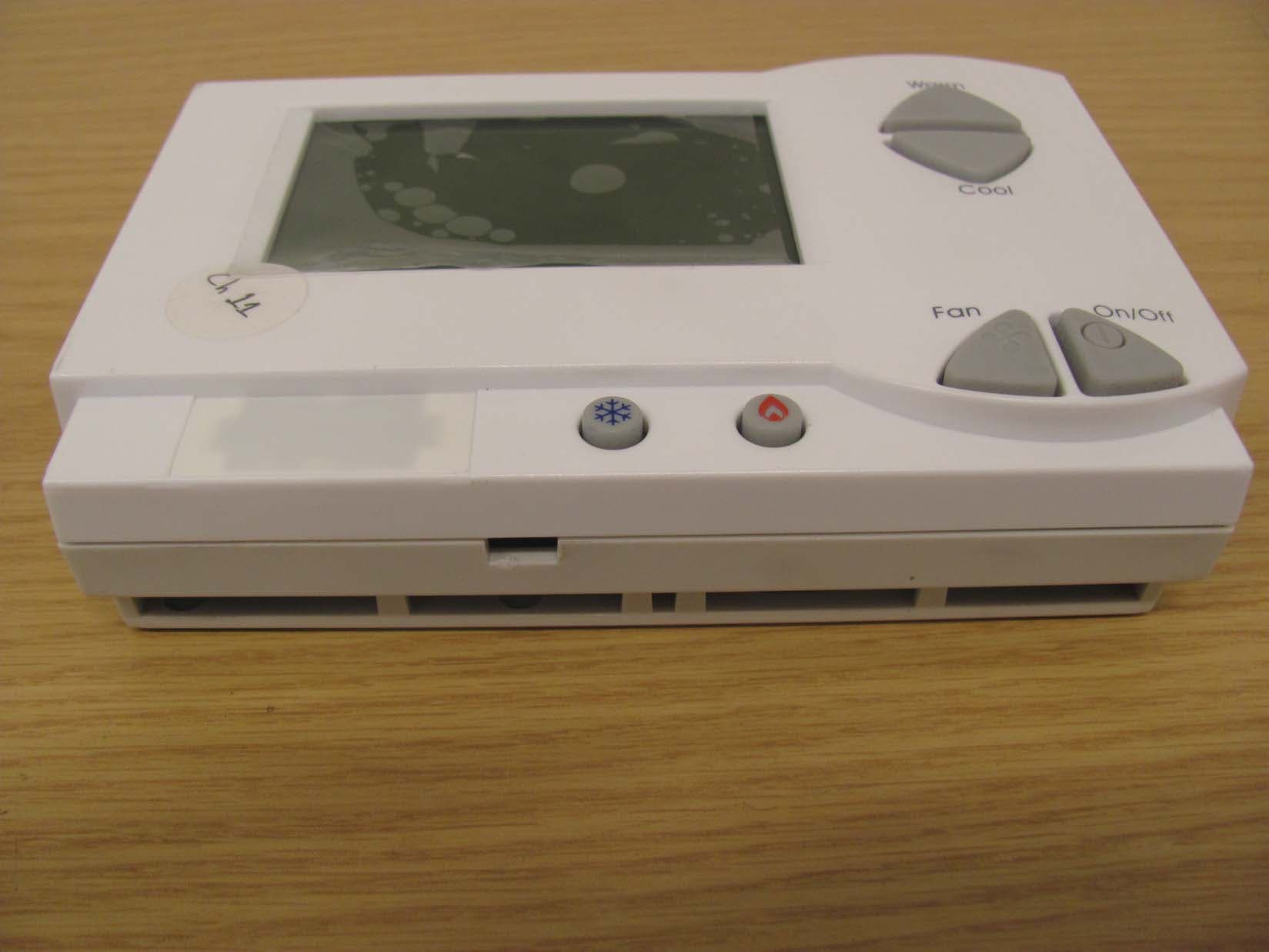
XV6PST6550
Sep 28, 2014EcoAir
Equipment Class
DXT - Part 15 Low Power Transceiver, Rx Verified
XV6PST62X0
Sep 28, 2014EcoView/EcoContact
Equipment Class
DXT - Part 15 Low Power Transceiver, Rx VerifiedXV6SS8030
Oct 27, 2013Load Control Module - Switch
Equipment Class
DXT - Part 15 Low Power Transceiver, Rx VerifiedXV6SS8020
Oct 27, 2013Load Control Module - Duplex Receptacle
Equipment Class
DXT - Part 15 Low Power Transceiver, Rx Verified