XVE-SA11200Track and Field Events Timing Transmitter
Traxxas LPApplication Details
- Equipment Class
- DTS - Digital Transmission System
- Date of Grant
- Jun 07, 2012
- Application Purpose
- Original Equipment
- Date of Application
- Jun 06, 2012
- Equipment Note
- Track and Field Events Timing Transmitter
- Frequency Range
- 2406.00000000 - 2453.00000000
- Company
- Traxxas LP
- Country
- United States
Documents & Files
Document Text
Text extracted from the exhibit documents filed with the FCC. Open a document above to read the original.
Users Manual
DTS User Manual Version 1.0 DTS Version: 1.0 User Manual Date: 2/23/2012 10:05:00 AM Confidential © Traxxas 2009 Page 2 of 7 Revision History Date Version Description Author 10/10/2011 1.0 Original. Chris S. Russell DTS Version: 1.0 User Manual Date: 2/23/2012 10:05:00 AM Confidential © Traxxas 2009 Page 3 of 7 Table of Contents 1. INTRODUCTION ............................................................................................................................................... 4 2. USERS GUIDE INFORMATION ...................................................................................................................... 5 2.1 ANTENNA REGULATION ................................................................................................................................. 5 2.2 EMISSIONS COMPLIANCE TESTING ................................................................................................................. 5 2.3 WORKING WITH ADDITIONAL TRANSMITTERS................................................................................................ 5 2.4 PRODUCT LABELING REQUIREMENTS ............................................................................................................. 6 3. FCC RF EXPOSURE STATEMENT ................................................................................................................ 7 DTS Version: 1.0 User Manual Date: 2/23/2012 10:05:00 AM Confidential © Traxxas 2009 Page 4 of 7 1. Introduction The user manual contains information pertaining to output power, operating frequency, operating channels, data rates, tuning range, intended use, general installation instructions, and antenna connector and gain information. . DTS Version: 1.0 User Manual Date: 2/23/2012 10:05:00 AM Confidential © Traxxas 2009 Page 5 of 7 2. Users Guide Information It is required that Traxxas LLP place the text below in the product user guide along with all other pertinent regulatory information. General Conditions: The following conditions must be strictly adhered to for modular approval: 1. No modification to the module including the circuitry is permitted. 2. Design criteria to include antenna, interconnects, and local oscillator. 3. Testing of the final device configuration for Digital Emissions Compliance The Spectrum 2.4 GHz, DTS may not be altered or modified in any manner by the OEM or other entity. Additionally, no component may be added which could change the radio frequency (RF) characteristics. These include, but are not limited to unintentional or spurious emissions, immunity, ESD characteristics, or other items commonly associated with RF devices. This includes all components; passive and active. Additionally, no RF components may be placed between the RF output of the module and the antenna. 2.1 Antenna Regulation The antenna has been selected and specifically tested with the Spectrum 2.4GHz, DTS, and has been certified through the regulatory agencies in the US and European Union authorized use. Use of any other antenna type used with this unit voids the LMA grant for the said module. 2.2 Emissions Compliance Testing Notwithstanding the Modular Approval for the device with associated antenna, the end product configuration must meet digital emissions compliance and must be tested in accordance with FCC Part 15 requirements confirming radiated emissions are within specified limits. Applicable FCC guidelines: • Part 15 Section 15.109 Sub-paragraph A, Class B Radiated Emission Limits. These emission tests can be conducted by the manufacturer or by contacting an approved test facility equipped and certified accordingly. The results of these emissions tests are not required to be submitted to the FCC or Traxxas, but should be kept on file by the OEM. 2.3 Working with Additional Transmitters The DTS should not be operated with any other transmitter in the end product. However, if such an application comes about, further regulatory compliance from the FCC must be obtained. DTS Version: 1.0 User Manual Date: 2/23/2012 10:05:00 AM Confidential © Traxxas 2009 Page 6 of 7 2.4 Product Labeling Requirements FCC product labeling requirements stipulate an FCC label, including specific text, be placed on the device containing the module. The product label must include the following text and must be affixed to the exterior of the final product. The text should be located beneath the FCC compliance logo. This product contains an integrated 2.4GHz (DSSS) radio. FCC ID: XVE-SA11200 In addition to the above text FCC Part 15.21 stipulates that the Digital Electronic Devices manufacturers must also have the following statements printed in their user/operations manual and/or indicate this exact text on the side of the final device. “This device complies with part 15 of the FCC Rules. Operation is subject to the following two conditions: (1) This device may not cause harmful interference, and (2) this device must accept any interference received, including interference that may cause undesired operation. Caution: Changes or modifications not expressly approved by the party responsible for compliance could void the user’s authority to operate the equipment. Note: The manufacturer is not responsible for any radio or TV interference caused by unauthorized modifications to this equipment. Such modifications could void the user’s authority to operate the equipment” DTS Version: 1.0 User Manual Date: 2/23/2012 10:05:00 AM Confidential © Traxxas 2009 Page 7 of 7 3. FCC RF Exposure Statement “This equipment complies with FCC radiation exposure limits set forth for an uncontrolled environment. End users must follow the specified operating instructions for satisfying RF exposure compliance. The antenna used for this transmitter must not be co-located or operating in conjunction with any other antenna or transmitter.” This document is provided “as is” with no warranties whatsoever including any warranty of merchantability, non-infringement, fitness for any particular …
Text truncated - open the document above for the full version.
External Photos
Spectrum 2.4GHz, Module Pictures Version 1.0 2.4GHz Transmitter Version: 1.0 Module Pictures Date: 8/1/2011 10:10am Confidential © Traxxas 2009 Page 2 of 7 Revision History Date Version Description Author 8/1/2011 1.0 Original. Chris S. Russell 2.4GHz Transmitter Version: 1.0 Module Pictures Date: 8/1/2011 10:10am Confidential © Traxxas 2009 Page 3 of 7 Table of Contents 1. PICTURES ........................................................................................................................................................... 5 2.4GHz Transmitter Version: 1.0 Module Pictures Date: 8/1/2011 10:10am Confidential © Traxxas 2009 Page 4 of 7 List of Figures Figure 1 2.4GHz Transceiver Top ................................................................................................................................. 5 Figure 2 2.4GHz Transceiver Bottom ............................................................................................................................ 6 Figure 3 2.4GHz Transceiver Top with RF can ............................................................................................................. 7 2.4GHz Transmitter Version: 1.0 Module Pictures Date: 8/1/2011 10:10am Confidential © Traxxas 2009 Page 5 of 7 1. Pictures Figure 1 2.4GHz Transceiver Top 2.4GHz Transmitter Version: 1.0 Module Pictures Date: 8/1/2011 10:10am Confidential © Traxxas 2009 Page 6 of 7 Figure 2 2.4GHz Transceiver Bottom 2.4GHz Transmitter Version: 1.0 Module Pictures Date: 8/1/2011 10:10am Confidential © Traxxas 2009 Page 7 of 7 Figure 3 2.4GHz Transceiver Top with RF can
Test Report
1601 North A.W. Grimes Blvd., Suite B Round Rock, TX78665 e-mail:[email protected] (512)244-3371 Fax:(512)244-1846 May 22, 2012 Traxxas, LLP 1100 Klein Road Plano, TX 75074 Dear Gary: Enclosed is the Wireless Test Report for the Drag Timing System Finish End by Traxxas. This report can be used to demonstrate compliance with FCC requirements for wireless devices in the United States. If you have any questions, please contact me. Sincerely, Jeffrey A. Lenk President Enclosure Professional Testing (EMI), Inc Traxxas, LLP–Drag Timing System Finish End Wireless Test Report 13461-10 May 22, 2012 Page 2 of 34 Project 13461-10 Traxxas, LLP Drag Timing System Finish End Wireless Test Report Revision 2 Prepared for: Traxxas, LLP 1100 Klein Road Plano, TX 75074 By Professional Testing (EMI), Inc. 1601 N. A.W. Grimes Blvd., Suite B Round Rock, Texas78665 May 22, 2012 Reviewed by Written by Jeffrey A. Lenk President Jesse Banda EMC Engineer Professional Testing (EMI), Inc Traxxas, LLP–Drag Timing System Finish End Wireless Test Report 13461-10 May 22, 2012 Page 3 of 34 Table of Contents Title Page .........................................................................................................................................1 1.0 Introduction ...........................................................................................................................6 1.1 Scope ................................................................................................................................6 1.2 EUT Description ..............................................................................................................6 1.3 Modifications ...................................................................................................................6 1.4 Test Site ...........................................................................................................................7 1.5 Applicable Documents .....................................................................................................7 1.6 Applicable Tests...............................................................................................................7 2.0 Maximum Peak Conducted Output Power ...........................................................................8 2.1 Test Procedure .................................................................................................................8 2.2 Test Criteria .....................................................................................................................8 2.3 Test Equipment ................................................................................................................8 2.4 Test Results ......................................................................................................................9 3.0 Occupied Bandwidth ...........................................................................................................10 3.1 Test Procedure ...............................................................................................................10 3.2 Test Criteria ...................................................................................................................10 3.3 Test Equipment ..............................................................................................................10 3.4 Test Result .....................................................................................................................10 4.0 Power Spectral Density .......................................................................................................14 4.1 Test Procedure ...............................................................................................................14 4.2 Test Criteria ...................................................................................................................14 4.3 Test Equipment ..............................................................................................................14 4.4 Test Results ....................................................................................................................14 5.0 Maximum Unwanted Emissions .........................................................................................18 5.1 Test Procedure ...............................................................................................................18 5.2 Test Criteria ...................................................................................................................18 5.3 Test Equipment ..............................................................................................................18 5.4 Test Results ....................................................................................................................19 6.0 Radiated Spurious Emission ...............................................................................................23 6.1 Test Procedure ...............................................................................................................23 6.2 Test Criteria ...................................................................................................................24 6.3 Test Equipment ..............................................................................................................24 6.4 Test Results ....................................................................................................................25 7.0 Band Edge Emissions .........................................................................................................31 7.1 Test Procedure ...............................................................................................................31 7.2 Test Criteria ...................................................................................................................31 7.3 Test Equipment ...................................................................…
Text truncated - open the document above for the full version.
Test Setup Photos
Radiated Emission Radiated Emission Conducted Emission Set up
Contact Information
Applicant
Scott Schmitz(Sr. Manager Electrical Engineering)
Technical Contact
Professinal Testing (EMI), Inc.Jesse Banda
[email protected]512-286-2175
1601 North A.W. Grimes · Round Rock · United States
Test Firm
Professional Testing (EMI), Inc.Larry Finn
Technical Specifications
| # | Rule Parts | Frequency Range | Power Output |
|---|---|---|---|
| 1 | 15C | 2.41 GHz - 2.45 GHz | 7.20 mW |
Other Applications from Traxxas LP
XVE-TRX1043
Sep 22, 2024Electronic Control Module(ECM) Brushless
Equipment Class
DTS - Digital Transmission System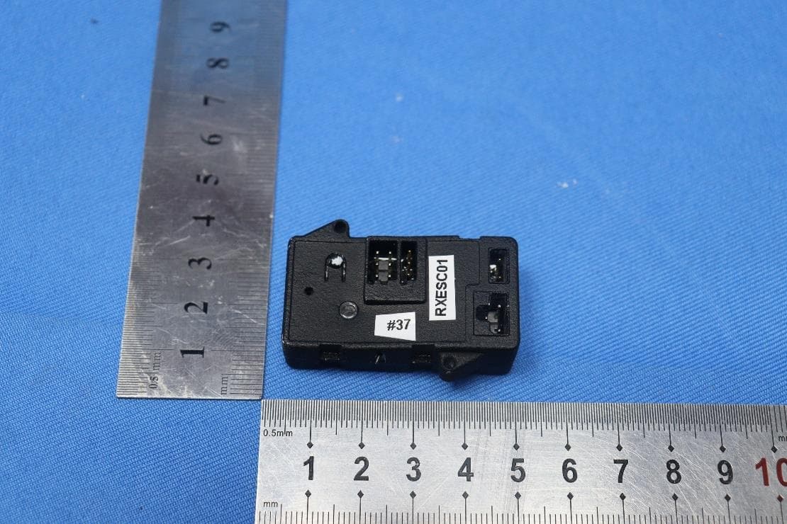
XVE-TRX1039
Mar 27, 2023Electronic Control Module (ECM-2.5)
Equipment Class
DTS - Digital Transmission System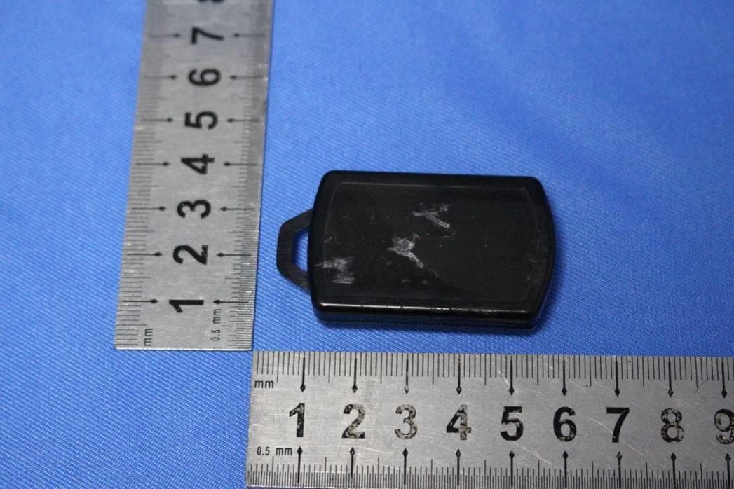
XVE-TRX1032
Apr 22, 2021Winch with Winch mount&Wireless Remote
Equipment Class
DXX - Part 15 Low Power Communication Device Transmitter
XVE-TRX1028
Feb 16, 2020TQi RADIO SYSTEMItem
Equipment Class
DTS - Digital Transmission System
XVE-TRX1029
Feb 16, 2020TQi RADIO SYSTEM
Equipment Class
DSS - Part 15 Spread Spectrum Transmitter