XWBCY08CHUMBY 8"
VIGORHOOD PHOTOELECTRIC SHENZHEN CO., LTD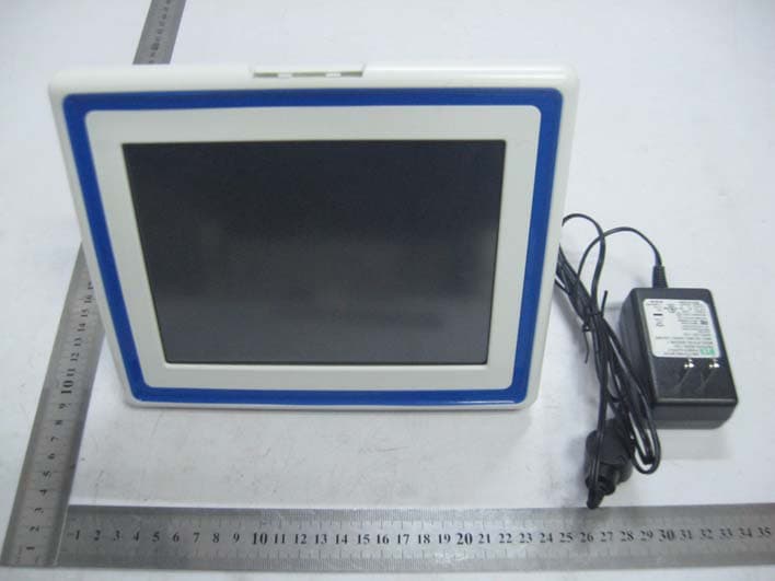
Click to zoom
Application Details
- Equipment Class
- DTS - Digital Transmission System
- Date of Grant
- Aug 25, 2011
- Application Purpose
- Original Equipment
- Date of Application
- Aug 25, 2011
- Equipment Note
- CHUMBY 8"
- Frequency Range
- 2412.00000000 - 2462.00000000
- Country
- China
Documents & Files
Document Text
Text extracted from the exhibit documents filed with the FCC. Open a document above to read the original.
Users Manual
ConnectMe ‐ Personal Internet View 1 Safety Instructions WARNING ‐‐ To reduce the risk of fire, electric shock, serious personal injury or product damage: • Adhere to all warnings in the operating instructions and on the product itself. • Use only manufacturer‐recommended attachments or accessories. • Do not use the Product near water; e.g. near a bathtub, washbowl, kitchen sink, laundry tub, in a wet basement, near a swimming pool, or expose to rain or moisture. If the product gets wet, unplug all cables. Wait for the product to dry completely before pressing the switch to power up again. Do not attempt to dry the product with an external heat source, such as a microwave oven or hair dryer. • Do not expose the Product to excessive heat or direct sunlight. Position the Product away from sources of high heat such as radiators or stoves or sun‐heated car or other appliances. • Connect the Product to a power supply only of the type described in the operating instructions or as marked on the unit. • Display the power cord so that it is not likely to be walked on or pinched by items placed on or against it, paying particular attention to the point where the cord attaches to the Product. ‐‐‐‐‐‐‐‐‐‐‐‐‐‐‐‐‐‐‐‐ • For added protection during a lightning storm, unplug the power cord from the wall outlet to prevent damage to the Product due to power line surges. • Do not overload wall outlets or extension cords. • Do not place objects onto or spill liquids on or inside the Product. • Avoid Condensation. Condensation may occur on internal operating parts of the product: 1. When the product is brought from the outdoors into a warm room, or if it is in a cold room which is heated quickly. 2. If the unit is moved suddenly from an air‐ conditioned room or car to a hot or humid location. • Should condensation occur, the product may not operate properly. Wait 1‐2 hours (to allow the internal parts to adjust to the surrounding temperature) before using the Product. • Clean the outer surface of the Product (excluding the screen) gently using a soft cloth. ConnectMe ‐ Personal Internet View 2 Do not use a solution containing alcohol, spirits, ammonia or abrasives for cleaning the product. Clean the screen only with a specified cleaning solution for use with products such as laptops and computer monitors. These are available at most retail consumer electronics stores. Do not clean the inside of the unit. • Do not twist or bend the Product. Avoid carrying the Product in pockets with keys or other objects that can damage the LCD Display. • Do not remove cover; there are no user‐serviceable parts inside. Do not attempt to service the Product beyond those means described in these operating instructions. All other servicing should be referred to qualified service personnel. • Seek service by qualified service personnel when: 1. The power supply has been damaged. 2. Liquid has been spilled onto the Product. 3. The Product has been exposed to rain. 4. The Product does not operate normally, or exhibits a marked change in performance. 5. The Product has been dropped or physically damaged. For users of models with Wireless LAN functionality • If radio interference with other devices occurs while using your device, do not use the Wireless LAN functionality. Use of the Wireless LAN functionality may cause a malfunction of the other devices, resulting in an accident. • Do not use the Wireless LAN functionality in any medical institutions, including hospitals, or while you are close to any electric medical equipment. Radio waves may cause a malfunction of such equipment, resulting in a serious accident. • Do not use the Wireless LAN functionality in an aircraft. Radio waves may cause a malfunction of the aircrafts equipment, resulting in a serious accident. • Do not use the Wireless LAN functionality in a crowded place, such as in crowded train car. Radio waves may cause a malfunction of pacemakers implanted in other people’s bodies. • If you urgently need to disable the Wireless LAN functionality, turn off the WIRELESS function. Features 9 8‐inch touch screen display with 800 x 600 resolution 9 2 GB of internal memory (approximately 1.5 GB is available for content storage) ConnectMe ‐ Personal Internet View 3 9 Touch screen menus 9 Easy to drag‐and‐drop interface 9 Internet‐enabled apps and updates from Chumby 9 No subscription fees 9 Share apps, photos, and videos with other users of Chumby‐enabled devices 9 Create an unlimited number of channels using any of over 1,500 apps and configure your apps the way you want to see them 9 Photo, music and video playback from internal memory or inserted memory cards and USB flash drives 9 Clock, alarm clock, and calendar 9 Night mode 9 Dimmable backlight 9 Headphone jack, stereo speakers built in 9 Memory card slots supports SD, SDHC, MMC, Memory Stick and MS Pro Duo. (using the non‐included adapter) 9 Dual USB ports support USB flash drives and more 9 UPnP ConnectMe ‐ Personal Internet View 4 Parts and Controls ConnectMe ‐ Personal Internet View 5 Packaging contents 1 x 8” ConnectMe, Personal Internet Viewer 1 x AC Power Adapter 1 x Instruction Manual System requirements - Broadband Internet connection (such as cable or DSL). The Product will not work with a dialup connection - Wireless router (802.11b/802.11g compatible). Most routers currently sold support these requirements. Routers supporting 802.11n may work with the Product as long as they properly support 802.11b or 802.11g. - Computer with Internet access. This is required to activate the Product and to configure the apps you want to show on it. After your device is set up, you will only need a computer to configure certain apps. ConnectMe ‐ Personal Internet View 6 Getting Started 1. Plug it in. Peel off the protective film from the front. Connect the power cord to the back and plug it into a wall outlet. Your chumby device should automatically power up (if it doesn't, just press the power button). 2. Choose a time zone. T…
Text truncated - open the document above for the full version.
External Photos
Vigorhood Photoelectric Shenzhen Co., Ltd Model: CY08 REPORT NO.: STR11088014I FCC PART 15.247 EXHIBIT 2 – EXTERNAL PHOTOGRAPHS EUT View 1 EUT View 2 Vigorhood Photoelectric Shenzhen Co., Ltd Model: CY08 REPORT NO.: STR11088014I FCC PART 15.247 EUT View 3 EUT View 4 (Black) Vigorhood Photoelectric Shenzhen Co., Ltd Model: CY08 REPORT NO.: STR11088014I FCC PART 15.247 EUT View 5 (Black)
ID Label/Location Info
Vigorhood Photoelectric Shenzhen Co., Ltd Model: CY08 REPORT NO.: STR11088014I FCC PART 15.247 EXHIBIT 1- PRODUCT LABELING Proposed FCC ID Label Format FCC ID: XWBCY08 This device complies with Part 15 of the FCC Rules. Operation is subject to the following two conditions: (1) This device may not cause harmful interference, and (2) This device must accept any interference received, including interference that may cause undesired operation. Specifications : Text is Black in color and justified. Labels are printed in indelible ink on permanent adhesive silk-screened onto the EUT or shall be affixed at a conspicuous location on the EUT. Proposed Label Location on EUT FCC ID Label Location
ID Label/Location Info
Vigorhood Photoelectric Shenzhen Co., Ltd Model: CY08 REPORT NO.: STR11088014I FCC PART 15.247 EXHIBIT 1- PRODUCT LABELING Proposed FCC ID Label Format FCC ID: XWBCY08 This device complies with Part 15 of the FCC Rules. Operation is subject to the following two conditions: (1) This device may not cause harmful interference, and (2) This device must accept any interference received, including interference that may cause undesired operation. Specifications : Text is Black in color and justified. Labels are printed in indelible ink on permanent adhesive silk-screened onto the EUT or shall be affixed at a conspicuous location on the EUT. Proposed Label Location on EUT FCC ID Label Location
Internal Photos
Vigorhood Photoelectric Shenzhen Co., Ltd Model: CY08 REPORT NO.: STR11088014I FCC PART 15.247 EXHIBIT 3 – INTERNAL PHOTOGRAPHS EUT Housing and Board View 1 EUT Housing and Board View 2 Vigorhood Photoelectric Shenzhen Co., Ltd Model: CY08 REPORT NO.: STR11088014I FCC PART 15.247 EUT Housing and Board View 3 Solder Board-Component View 1 Vigorhood Photoelectric Shenzhen Co., Ltd Model: CY08 REPORT NO.: STR11088014I FCC PART 15.247 Solder Board-Component View 2 Solder Board-Component View 3 Vigorhood Photoelectric Shenzhen Co., Ltd Model: CY08 REPORT NO.: STR11088014I FCC PART 15.247 Solder Board-Component View 4 Solder Board-Component View 5 Vigorhood Photoelectric Shenzhen Co., Ltd Model: CY08 REPORT NO.: STR11088014I FCC PART 15.247 Solder Board-Component View 6
Operational Description
Circuit Description 1. The Marvell 88AP166-A0-BJD2C008 chip is master micro controller, the oscillator component Y102 generated a frequency of 26MHz as base clock frequency, it is a center processing unit which the master frequency of running speed is 333MHz, with 1GB DDR memory, and SD card socket, one USB port for external USB disk. 2. The AW-GH321 WiFi module base on 802.11b/g WIFI wireless technolgy, use the high-frequency from 2412MHz to 2462MHz as carrier frequency for 802.11b/g, the CCK, OFDM modulation type be used. 3. The USB disk and SD card all external signal and data input to MCU as program source, playing and display on LCD screen. 4. The work voltage is DC 5V, supply by external power adaptor.
RF Exposure Info
RF Exposure Requirements Product Description: Chumby 8” Model No.: CY08 FCC ID: XWBCY08 Acorrding to the KDB-447498, the following RF exposure evaluation shall to demonstrate RF exposure compliance. Tx frequency range: 2412~2462MHz Antenna-to-tissue separation: <20 cm Maximum antenna gain: 2dBi Maximum Output Power: 23.18mW (at the 2412MHz channel of 802.11b mode) Maximum Duty Factor: 100% 60/f(GHz) mW = 24.87 mW Source-based time-averaged conducted output power is 23.18 mW =< 60/f So the transmitter comply with the RF exposure requirements and the SAR is not required.
Schematics
11 22 33 44 55 66 D D C C B B A A Title Number Revision Size B Date: 6/17/2010 Sheet of File: S:\silvermoon_chb801_v3\..cpu_membus_posteq.SchDoc Drawn By: Please see the HDK license agreement for terms of use at http://www.chumby.com/legal/developer (R) 1OF12 M0_DQSP1 V5 M0_DQ0 P2 M0_DQ1 P3 M0_DQ2 P4 M0_DQ3 R3 M0_DQ4 T3 M0_DQ5 U1 M0_DQ6 U2 M0_DQ7 V1 M0_DQ8 V3 M0_DQ9 U4 M0_DQ10 R5 M0_DQ11 T5 M0_DQ12 P6 M0_DQ13 R6 M0_DQ14 T6 M0_DQ15 U7 M0_MA1 U10 M0_MA3 R11 M0_MA4 U11 M0_MA5 V11 M0_MA6 V12 M0_MA7 U12 M0_MA8 T12 M0_MA9 R12 M0_MA10 V13 M0_MA11 U13 M0_MA12 R13 M0_MA13 P13 M0_MA14 R14 M0_BA0 T9 M0_BA1 R9 M0_BA2 P10 M0_RAS V8 M0_CAS V9 M0_ODT U8 M0_DM0 P1 M0_DM1 V2 M0_DQSN0 R1 M0_DQSP0 T1 M0_DQSN1 V4 M0_CKP0 V6 M0_CKN0 V7 M0_CKE R7 M0_WE U9 M0_CS R8 CALPAD N4 M0_MA2 V10 M0_MA0 R10 U100AMarvell 88AP166-A0-BJD2C008 M0_MA0M0_MA1M0_MA2M0_MA3M0_MA4M0_MA5M0_MA6M0_MA7M0_MA8M0_MA9M0_MA10M0_MA11M0_MA12M0_MA13M0_MA14 M0_DQ0M0_DQ1M0_DQ2M0_DQ3M0_DQ4M0_DQ5M0_DQ6M0_DQ7M0_DQ8M0_DQ9M0_DQ10M0_DQ11M0_DQ12M0_DQ13M0_DQ14 M0_DQ15M0_BA0M0_BA1M0_BA2M0_RAS_NM0_CAS_NM0_ODT M0_DM0M0_DM1M0_DQS0_NM0_DQS0_PM0_DQS1_NM0_DQS1_P M0_CK0_PM0_CK0_NM0_CKEM0_WE_NM0_CS_N i DDR_CK i DDR_CK 6OF12 SMC_RDY B14 SMC_SCLK A14 DF_ADDR0 B13 DFI_D6 D17 DFI_D7 D18 MMC3_CMD/DFI_D15 F18 MMC3_CL K/DFI_D14 F17 DFI_D13 F16 DFI_D12 F15 MMC3_D3/DFI_D11 E18 MMC3_D2/DFI_D10 E17 MMC3_D1/DFI_D9 E16 MMC3_D0/DFI_D8 E15 DFI_D5 D16 DFI_D4 D15 DFI_D3 C18 DFI_D2 C17 ND_RDY0 E13 DFI_D1 B18 ND_CE0 A18 SMC_CS A16 GPIO_20 C15 ND_ALE B15 ND_CLE A15 SMC_LUA D14 SMC_LLA D13 ND_RDY1/SMC_IRQ C13 DF_ADDR1 A13 DF_ADDR2 D12 DF_ADDR3 B12 GPIO_34 C12 GPIO_35 A12 GPIO_36 E12 DFI_D0 B17 ND_CE1 B16 ND_WE A17 ND_RE C14 U100FMarvell 88AP166-A0-BJD2C008 A0 M8 A1 M3 A2 M7 A3 N2 A4 N8 A5 N3 A6 N7 A7 P2 A8 P8 A9 P3 A10 M2 A11 P7 A12 R2 BA0 L2 BA1 L3 BA2 L1 WE K3 RAS K7 CAS L7 CS L8 CK J8 CK K8 CKE K2 ODT K9 DQ0 G8 DQ1 G2 DQ2 H7 DQ3 H3 DQ4 H1 DQ5 H9 DQ6 F1 DQ7 F9 DQ8 C8 DQ9 C2 DQ10 D7 DQ11 D3 DQ12 D1 DQ13 D9 DQ14 B1 DQ15 B9 VDD A1 VSS A3 VSSQ A7 UDQS A8 UDQS B7 LDQS F7 LDQS E8 VSSQ B2 UDM B3 VSSQ B8 VDDQ C1 VDDQ C3 VDDQ C7 VDDQ C9 VSSQ D2 VSSQ D8 VDD E1 VSS E3 VSSQ E7 VDDQ E9 VSSQ F2 LDM F3 VSSQ F8 VDDQ G1 VDDQ G3 VDDQ G7 VDDQ G9 VSSQ H2 VSSQ H8 VDDL J1 VREF J2 VSS J3 VSSDL J7 VDD J9 VDD M9 VSS N1 VSS P9 VDD R1 VDDQ A9 NC/A13 R8 NC/A14 R3 U2011Gbit x16 DDR2 RAM GND P1.8V P1.8V GND R200100, 1% ddr_vref iDDR_D0iDDR_D1iDDR_D0iDDR_D0iDDR_D0iDDR_D0iDDR_D0iDDR_D0iDDR_D0iDDR_D0iDDR_D0iDDR_D0iDDR_D1iDDR_D1iDDR_D1iDDR_D1iDDR_D1iDDR_D1iDDR_D1iDDR_D1iDDR_D1iDDR_D1 i DDR_CTL i DDR_CTL i DDR_CTL i DDR_CTL i DDR_CTL i DDR_CTL i DDR_CTL i DDR_CTL i DDR_CTL i DDR_CTL i DDR_CTL i DDR_CTL i DDR_CTL i DDR_CTL i DDR_CTL i DDR_CTL i DDR_CTL i DDR_CTL i DDR_CTL i DDR_CTL i DDR_CTL i DDR_CTL C202 0.01uF, 10V, X5R C203 0.01uF, 10V, X5R C204 0.01uF, 10V, X5R C205 0.01uF, 10V, X5R C206 0.01uF, 10V, X5R C207 0.01uF, 10V, X5R C208 0.01uF, 10V, X5R C209 0.01uF, 10V, X5R P1.8V GND R1071k, 1% R2021k, 1% GND P1.8V C212 0.01uF, 10V, X5R GND ddr_vref C2114.7uF, 10V, X5R 0805 GND C201 0.1uF, 10V, X5R C200 0.1uF, 10V, X5R C2134.7uF, 10V, X5R 0805 C2104.7uF, 10V, X5R 0805 P1.8V GND 1 J209test point (DNP) C257 0.01uF, 10V, X5R GND ddr_vref C258 0.01uF, 10V, X5R GND R103DNP GND M0_MA1M0_MA2M0_MA3M0_MA4M0_MA5M0_MA6M0_MA7M0_MA8M0_MA9M0_MA10M0_MA11M0_MA12M0_MA0M0_BA0M0_BA1M0_BA2M0_RAS_NM0_CAS_NM0_CS_NM0_WE_NM0_CK0_PM0_CK0_NM0_CKEM0_ODT M0_DQ0M0_DQ1M0_DQ2M0_DQ3M0_DQ4M0_DQ5M0_DQ6M0_DQ7M0_DQ8M0_DQ9M0_DQ10M0_DQ11M0_DQ12M0_DQ13M0_DQ14M0_DQ15 M0_DQS1_NM0_DQS1_P M0_DQS0_NM0_DQS0_PM0_DM0M0_DM1 DFI_D0DFI_D1DFI_D2DFI_D3DFI_D4DFI_D5DFI_D6DFI_D7 • Route VREF with a 20–25 mil minimum trace to reduce inductance • Maintain at least a 15–25 mil clearance from VREF to other adjacent traces • Place a 0. 1μF capacitor between VREF and VDDQ • Place a 0.1μF capacitor between VREF and VSSQ • Decouple at each device or connector to minimize noise at each component (Per Micron TN-46-14) 1 8 2 7 3 6 4 5 RP103 0/RP 1 4 2 3 RP111 0/RP 1 8 2 7 3 6 4 5 RP108 0/RP 1 8 2 7 3 6 4 5 RP102 0/RP R P 3 R P 1 0 3 0 / RR P 1 8 2 7 3 6 4 5 RP101 0/RP 1 8 2 7 3 6 4 5 RP106 0/RP R P 1 0 8 0 / R 1 0 / RR P 1 8 2 7 3 6 4 5 RP110 0/RP 1 8 2 7 3 6 4 5 RP105 0/RP 1 8 2 7 3 6 4 5 RP107 0/RP R 0 R P 1 0 1 / R P / 1 8 2 7 3 6 4 5 RP100 0/RP 1 8 2 7 3 6 4 5 RP109 0/RP R P 1 0 / R P R P P 1 0 1 4 2 3 RP112 0/RP 1 4 2 3 RP113 0/RP bottomtopbottomtoptopbottom bottombottomtoptoptoptoptop toptop R2010 Rules:Traces within byte lane: +/- 60 mil match All traces with respect to clock: +/- 200 mil match Within a differential pair: +/- 10 mil match Use 4 mil routing stack from JEDEC Standard No. 21C, Page 4.20.13-46 M0_MA13M0_MA14 i DDR_CTL i DDR_CTL R P 1 0 2 0 / R 1 0 / RR P 1 8 2 7 3 6 4 5 22 RP104 0/RP R109301, 1% GND R1293.3k, 5% (DNP) R1303.3k, 5% (DNP) R1313.3k, 5% (DNP) R1323.3k, 5% (DNP) R1333.3k, 5% (DNP) R1343.3k, 5% (DNP) R1353.3k, 5% (DNP) R1363.3k, 5% (DNP) GND DFI_D0DFI_D1DFI_D2DFI_D3DFI_D4DFI_D5DFI_D6DFI_D7 MMC3_D0MMC3_D1MMC3_D2MMC3_D3 MMC3_ALT_CMD MMC3_ALT_CLK Copyright 2008 - 2010 Chumby Industries Silvermoon OEM ref v3 11 22 33 44 55 66 D D C C B B A A Title Number Revision Size B Date: 6/17/2010 Sheet of File: S:\silvermoon_chb801_v3\cpu_io.SchDoc Drawn By: XuTXD_0 XnRESET_LV 12 C10310pF, NP0 12 C10210pF, NP0 12 Y10226.0000 MHz (NDK NX3225SA) XusbhD_PXusbhD_N HOST_TO_CP_UARTCP_TO_HOST_UART GND 12345 J101Header 5 (4x1) (DNP) XuTXD_0_LV P3.3V XuRXD_0_LV Serial console I2S_CLK0I2S_CDCLK0I2S_LRCLK0I2S_DI0I2S_DO0 HP_IN CHUMBY_BEND Please see the HDK license agreement for terms of use at http://www.chumby.com/legal/developer (R) XDCDNSDCDNCFCDNMSINS AP_TDIAP_TMSAP_TCKAP_TRST RTCK AP_TDO R15DNP R13 DNP R14 33, 5% R310K, 5% (DNP) R210K, 5% 2468 10121416 13579111315 J1 HEADER 8X2 (DNP) R410K, 5% (DNP) R10 R510K, 5% R16DNP R610K, 5% (DNP) P1.8V P1.8V JTAG ASPEN - 1.8V 2OF12 USBH_DN M18 USBH_DP M17 USBOTG_DP N17 USBID M15 USBVBUS P17 USBOTG_DN N18 2 O F 1 2 N U100BMarvell 88AP166-A0-BJD2C008 3OF12 I2C0_SCL/AC97_SYSCLK/GPIO_106 F1 I2C0_SDA/SSP4_TXD/GPIO_105 F2 SSP4_RXD/GPIO_1…
Text truncated - open the document above for the full version.
Test Report
Vigorhood Photoelectric Shenzhen Co., Ltd Model: CY08 REPORT NO.: STR11088014I PAGE 1 OF 45 FCC PART 15.247 FCC Part 15C Measurement and Test Report For Vigorhood Photoelectric Shenzhen Co., Ltd F Building, Hongfa Tech Industrial Park, Songbai Rd. Shiyan Town, Baoan District, Shenzhen, China FCC ID: XWBCY08 Report Concerns: Original Report Equipment Type: Chumby 8’’ Model: CY08 Report No.: STR11088014I Test Date: 2011-08-01 to 2011-08-22 Issue Date: 2011-08-26 Tested By: Vigoss Xiong / Engineer Reviewed By: Lahm Peng / EMC Manager Approved & Authorized By: Jandy so / PSQ Manager Prepared By: SEM.Test Compliance Service Co., Ltd 3/F, Jinbao Commerce Building, Xin'an Fanshen Road, Bao'an District, Shenzhen, P.R.C.(518101) Tel.: +86-755-33663308 Fax.: +86-755-33663309 Website: www.semtest.com.cn Note: This test report is limited to the above client company and the product model only. It may not be duplicated without prior permitted by SEM.Test Compliance Service Co., Ltd . Vigorhood Photoelectric Shenzhen Co., Ltd Model: CY08 REPORT NO.: STR11088014I PAGE 2 OF 45 FCC PART 15.247 TABLE OF CONTENTS 1. GENERAL INFORMATION ...................................................................................................................................3 1.1 PRODUCT DESCRIPTION FOR EQUIPMENT UNDER TEST (EUT)...............................................................................3 1.2 TEST STANDARDS...................................................................................................................................................3 1.3 TEST METHODOLOGY.............................................................................................................................................4 1.4 TEST FACILITY.......................................................................................................................................................4 1.5 EUT EXERCISE SOFTWARE....................................................................................................................................4 1.6 ACCESSORIES EQUIPMENT LIST AND DETAILS.......................................................................................................4 1.7 EUT CABLE LIST AND DETAILS.............................................................................................................................4 2. SUMMARY OF TEST RESULTS ...........................................................................................................................5 3. CONDUCTED EMISSIONS ....................................................................................................................................6 3.1 MEASUREMENT UNCERTAINTY..............................................................................................................................6 3.2 TEST EQUIPMENT LIST AND DETAILS.....................................................................................................................6 3.3 TEST PROCEDURE...................................................................................................................................................6 3.4 BASIC TEST SETUP BLOCK DIAGRAM.....................................................................................................................6 3.5 ENVIRONMENTAL CONDITIONS..............................................................................................................................7 3.6 SUMMARY OF TEST RESULTS/PLOTS......................................................................................................................7 3.7 CONDUCTED EMISSIONS TEST DATA......................................................................................................................7 4. §15.203 - ANTENNA REQUIREMENT................................................................................................................10 4.1 STANDARD APPLICABLE.......................................................................................................................................10 4.2 TEST RESULT........................................................................................................................................................10 5. POWER SPECTRAL DENSITY ...........................................................................................................................11 5.1 STANDARD APPLICABLE.......................................................................................................................................11 5.2 TEST EQUIPMENT LIST AND DETAILS...................................................................................................................11 5.3 TEST PROCEDURE.................................................................................................................................................11 5.4 ENVIRONMENTAL CONDITIONS............................................................................................................................11 5.5 SUMMARY OF TEST RESULTS/PLOTS....................................................................................................................12 6. 6-DB BANDWIDTH ................................................................................................................................................16 6.1 STANDARD APPLICABLE.......................................................................................................................................16 6.2 TEST EQUIPMENT LIST AND DETAILS...................................................................................................................16 6.3 TEST PROCEDURE.................................................................................................................................................16 6.4 ENVIRONMENTAL CONDITIONS............................................................................................................................16 6.5 SUMMARY OF TES…
Text truncated - open the document above for the full version.
Test Setup Photos
Vigorhood Photoelectric Shenzhen Co., Ltd Model: CY08 REPORT NO.: STR11088014I FCC PART 15.247 EXHIBIT 4 - TEST SETUP PHOTOGRAPHS Conduction Emission View Radiation Emission Test Setup (30MHz to 1GHz) Vigorhood Photoelectric Shenzhen Co., Ltd Model: CY08 REPORT NO.: STR11088014I FCC PART 15.247 Radiation Emission Test Setup (Above 1GHz)
Contact Information
Applicant
Mikes Zou(R&D Dept HW Section Chief)
Test Firm
SEM.Test Compliance Service Co., Ltd.Jandy So
Technical Specifications
| # | Rule Parts | Frequency Range | Power Output |
|---|---|---|---|
| 1 | 15C | 2.41 GHz - 2.46 GHz | 15.00 mW |
Other Applications from VIGORHOOD PHOTOELECTRIC SHENZHEN CO., LTD
XWBLK01
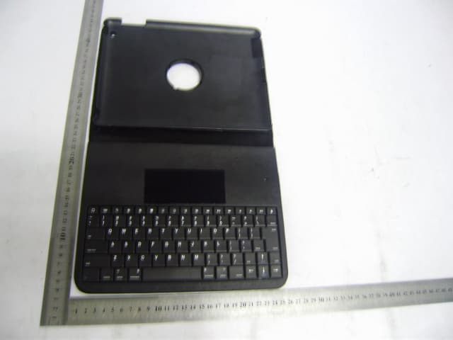
Oct 12, 2011WIRELESS KEYBOARD & LEATHER PORTFOLIO
Equipment Class
DSS - Part 15 Spread Spectrum Transmitter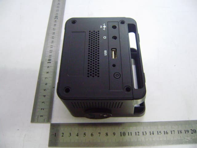
XWBCY35
Sep 28, 2011CHUMBY 3.5 INCH MULTI-MEDIA DEVICE
Equipment Class
JBP - Part 15 Class B Computing Device Peripheral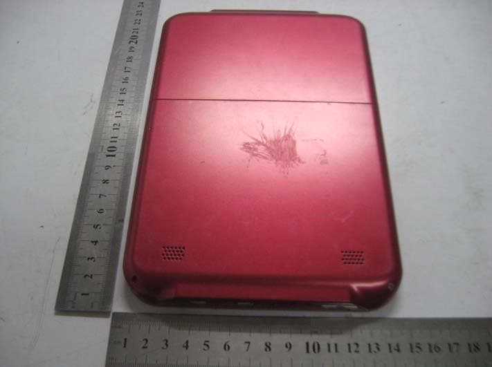
XWBEB60
Nov 22, 2010MID EBOOK READER
Equipment Class
JBP - Part 15 Class B Computing Device Peripheral