XWBCY35CHUMBY 3.5 INCH MULTI-MEDIA DEVICE
VIGORHOOD PHOTOELECTRIC SHENZHEN CO., LTD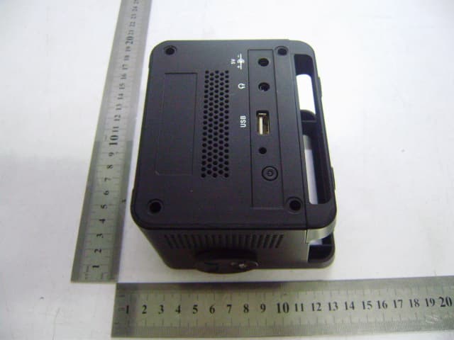
Click to zoom
Application Details
- Equipment Class
- JBP - Part 15 Class B Computing Device Peripheral
- Date of Grant
- Sep 28, 2011
- Application Purpose
- Original Equipment
- Date of Application
- Sep 28, 2011
- Equipment Note
- CHUMBY 3.5 INCH MULTI-MEDIA DEVICE
- Country
- China
Documents & Files
Document Text
Text extracted from the exhibit documents filed with the FCC. Open a document above to read the original.
Users Manual
Getting Started 1. Remove the clear protective film from the touchscreen. 2. Connect the AC adapter (provided) to the back of your chumby one and plug it into a wall outlet. 3. Follow the instructions on the touchscreen. You’ll need access to a computer to activate your chumby one. Touchscreen Tip: Tap the screen to make selections, using the very tip of your finger(or your fingernail)and not the full pad of your fingertip. Tapping the screen –as opposed to pressing hard on the screen –works the best. For detailed set‐up instructions, Visit www.chumby.com/pages/start Connecting to the internet To create a new network connection or use an existing one, press the top of the chumby to open the control panel and then tap Settings > Network. This screen lets you choose a new or existing connection: • To create a new connection, tap create a new connection and tap OK. • To use an existing connection (one you've previously set up on this chumby), tap use an existing connection and tap OK. First time users: If this is the first time you've ever turned on your chumby, you won't see this screen. Which screen do you see? Click on the screen that matches the one you see on your chumby and you'll Continue on to the next series of set‐up screens. Choose a wireless connection* Choose a network configuration* Choose a network adapter * The actual list of network names shown on your screen will be different. Shock hazard! Do not near water. This is not a toy –possible choking hazard. Intended for people Use only the power supply provided with the unit. We recommend using only a Fujifilm NP‐120 battery or other equivalent battery having the same performance and safety features. Use of a different battery may void your warranty and/or result in damage, fire, personal injury or reduced device performance. Customer support Questions about your chumby one? Go to the Help area at www.chumby.com/help , where you’ll find commonly asked questions, troubleshooting guides, and complete customer support information. Registration To be able to play widgets on your chumby one, you must activate it at www.chumby.com . When you activate your device it’s automatically registered so you’ll be kept up‐to‐date on important software and hardware issues that might affect it. Note: Product registration is voluntary; failure to register will not diminish your limited warranty rights. GNUGP Land LGPL The GPL and LGPL source code contained in this product is as a free download from http://files.chumby.com/ source. The licenses for the GPL and LGPL are available on the chumby device by accessing the Control Panel and then selecting Settings>Chumby Info>Software Licenses. The licenses are also available on www.chumby.com/pages /legal. One‐Yea r Limited Warranty Warrants the chumby electronic device (the“product”),and only the product, against defects in materials and workmanship under normal use for a period of ONE(1) YEAR from the date of retail purchase by the original purchaser(“Warranty Period). Under this Limited Warranty, if a hardware defect arises and a valid claim is received by chumby within the Warranty Period, at its option and to the extent permitted by law, chumby will either (1) repair the product at no charge. Using new or refurbished replacement parts,(2)exchange the product with a new or refurbished product, or (3) refund the purchase price of the product. In the event of a defect, to the extent permitted by law, these are your sole and exclusive remedies. This Limited Warranty is valid only in the United States for products sold in the United States. A replacement product or part assumes the remaining warranty of the original product or ninety(90)days from the date of replacement or repair, whichever is longer. When a product or part of the product is exchanged, any replacement item becomes your property and the replaced item becomes your property and the replaced item becomes Chumby’s property. If chumby elects to refund the purchase price, then to receive a refund you must return the product obligation must be used in products for which warranty service is claimed. Instructions is to Obtain Warranty Service: To obtain warranty service, you must deliver the product, freight prepared, in either its original packing or packing providing an equal degree of protection, to the address specified by chumby. In accordance with applicable law, chumby may require that you furnish proof of purchase details and/or comply with registration requirements before receiving warranty service. It is your responsibility to backup any data, software, or other materials you may have stored or preserved on the product. It is likely that such data, software, or other materials will be lost or reformatted during service, and chumby will be not responsible for any such damage or loss. For specific instructions on how to obtain warranty service on your product, visit the chumby website (www.chumby.com/pages/returns ) or write to us at chumby industries, Inc., 12264 EL Camino Real, Suite 203, San Diego, CA 92130, Attn: Warranty Service. Exclusions and Limitations. This Limited Warranty applies only to the hardware product manufactured by or for chumby that can be identified by the “chumby” trademark, trade name, or logo affixed to it. The Limited Warranty does not apply to any (a) chumby products and services other than the product, (b) non‐chumby hardware product, (c) consumables (such as batteries), or (d) software, even if packaged or sold with the product or embedded in the product. Refer to the licenses accompanying the software for details of your rights with respect to its use. Chumby does not warrant that the operation of the product will be uninterrupted or error‐free. Chumby is not responsible for damage arising from failure to follow instructions relating to the product’s use. This warranty does not apply to a product or part of the product that has been altered or modified (e.g., to alter functionality or capability by anyone wh…
Text truncated - open the document above for the full version.
Block Diagram
Block Diagram MCU i.MX233 USB WIFI Module XTAL 32.768kHz LCD Display USB Card SD Card DC Power Supply Key DDR Ant. 2412-2462MHz Earphone
Cover Letter(s)
Vigorhood Photoelectric Shenzhen Co., Ltd F Building, Hongfa Tech Industrial Park, Songbai Rd. Shiyan Town, Baoan District, Shenzhen, China Statement September 16, 2011 Dear Timco Engineering, Inc., Thank you for cooperation. Produc Description: Chumby 3.5 inch Multi-Media Device FCC ID: XWBCY35 Best Regards, We are sure that for this product of the case described above, the co-located WIFI module is identical to the unit originally granted(FCC ID:ZXVHLK-2MXX),and due to the type of the module’s antenna is PCB type, so the module’s antenna is integrated, please be informed. Vigorhood Photoelectric Shenzhen Co., Ltd
External Photos
Vigorhood Photoelectric Shenzhen Co., Ltd Model: CY35 REPORT NO.: STR11068003I FCC PART 15C EXHIBIT 2 – EXTERNAL PHOTOGRAPHS EUT View 1 EUT View 2
ID Label/Location Info
Vigorhood Photoelectric Shenzhen Co., Ltd Model: CY35 REPORT NO.: STR11068003I FCC PART 15C EXHIBIT 1- PRODUCT LABELING Proposed FCC ID Label Format FCC ID: XWBCY35 Contains FCC ID: ZXVHLK-2MXX This device complies with Part 15 of the FCC Rules. Operation is subject to the following two conditions: (1) This device may not cause harmful interference, and (2) This device must accept any interference received, including interference that may cause undesired operation. Specifications : Text is Black in color and justified. Labels are printed in indelible ink on permanent adhesive silk-screened onto the EUT or shall be affixed at a conspicuous location on the EUT. Proposed Label Location on EUT FCC ID Label Location
ID Label/Location Info
Vigorhood Photoelectric Shenzhen Co., Ltd Model: CY35 REPORT NO.: STR11068003I FCC PART 15C EXHIBIT 1- PRODUCT LABELING Proposed FCC ID Label Format FCC ID: XWBCY35 Contains FCC ID: ZXVHLK-2MXX This device complies with Part 15 of the FCC Rules. Operation is subject to the following two conditions: (1) This device may not cause harmful interference, and (2) This device must accept any interference received, including interference that may cause undesired operation. Specifications : Text is Black in color and justified. Labels are printed in indelible ink on permanent adhesive silk-screened onto the EUT or shall be affixed at a conspicuous location on the EUT. Proposed Label Location on EUT FCC ID Label Location
Internal Photos
Vigorhood Photoelectric Shenzhen Co., Ltd Model: CY35 REPORT NO.: STR11068003I FCC PART 15C EXHIBIT 3 – INTERNAL PHOTOGRAPHS EUT Housing and Board View 1 Solder Board-Component View 1 Vigorhood Photoelectric Shenzhen Co., Ltd Model: CY35 REPORT NO.: STR11068003I FCC PART 15C Solder Board-Component View 2 Solder Board-Component View 3 Vigorhood Photoelectric Shenzhen Co., Ltd Model: CY35 REPORT NO.: STR11068003I FCC PART 15C Solder Board-Component View 4 Solder Board-Component View 5 Vigorhood Photoelectric Shenzhen Co., Ltd Model: CY35 REPORT NO.: STR11068003I FCC PART 15C Solder Board-Component View 6 Solder Board-Component View 7 Vigorhood Photoelectric Shenzhen Co., Ltd Model: CY35 REPORT NO.: STR11068003I FCC PART 15C Solder Board-Component View 8 Solder Board-Component View 9
Operational Description
Circuit Description 1. The i.MX233 chip is master micro controller, the oscillator component Y101 generated a frequency of 32.768kHz as base clock frequency, it is a center processing unit which the master frequency of running speed up to 454MHz, with 1GB DDR memory, and SD card socket, one USB port for external USB disk. 2. The USB WiFi module(FCC ID:ZXVHLK-2MXX) base on 802.11b/g WIFI wireless technolgy, use the high-frequency from 2412MHz to 2462MHz as carrier frequency for 802.11b/g, the CCK, OFDM modulation type be used. 3. The USB disk and SD card all external signal and data input to MCU as program source, playing and display on LCD screen, audio output to the earphone. 4. The work voltage is DC 5V, supply by external power adaptor.
Schematics
1 1 2 2 3 3 4 4 5 5 6 6 DD CC BB AA Title NumberRevisionSize A Date:8/6/2010Sheet of File:R:\falconwing\falconwing_8\cpu.SchDocDrawn By: DCDC_VDDA XTALIXTALO VAG XTALI XTALO RTC_XTALI RTC_XTALO BATT VDDXTAL DCDC_VDDIO DCDC_LN1 DCDC_VDDD DCDC_LP XTALO XTALI PSWITCH_i R114 100K, 5% C128 4.7uF, 10V, X5R STMP3780 Huashan 169-BGA EMI_D00 K10 EMI_D01 M10 EMI_D02 N11 EMI_D03 N10 EMI_D04 M11 EMI_D05 K9 EMI_D06 L11 EMI_D07 L9 EMI_D08 N9 EMI_D09 N8 EMI_D10 M8 EMI_D11 K7 EMI_D12 L7 EMI_D13 K6 EMI_D14 N7 EMI_D15 M7 EMI_A00 K13 EMI_A01 K12 EMI_A02 J13 EMI_A03 K11 EMI_A04 G10 EMI_A05 G12 EMI_A06 F12 EMI_A07 G11 EMI_A08 G13 EMI_A09 F13 EMI_A10 J12 EMI_A11 H10 EMI_A12 H13 EMI_CE0n J10 EMI_CE1n H12 EMI_DQM0 M12 EMI_DQM1 M9 EMI_RASn N13 EMI_CASn M13 EMI_WEn J11 EMI_CKE F11 EMI_CLK M6 LCD_D00 D3 LCD_D01 E2 LCD_D02 E4 LCD_D03 F1 LCD_D04 F3 LCD_D05 F5 LCD_D06 G2 LCD_D07 G5 LCD_D08 H2 LCD_D09 H3 LCD_D10 H1 LCD_D11 G4 LCD_D12 G1 LCD_D13 F4 LCD_D14 F2 LCD_D15 E5 LCD_CS H4 LCD_RS / LCD_CCIRCLK J3 LCD_RESET J5 LCD_WR_E J4 AUART1_RX H8 AUART1_TX J8 AUART1_CTS G7 AUART1_RTS H7 DEBUG E12 VDDIO_EMI2 L10 VDDIO33_1 E11 VSSIO_EMI1 J7 VSSD1 D6 VSSIO_EMI2 J9 VDDD1 D5 VDDD3 D8 DCDC_BATT B11 DCDC_VDDD D13 DCDC_VDDIO C13 DCDC_GND A13 DCDC_LN1 B13 VDDM C10 DCDC_LP A12 PSWITCH B3 VDD5V E13 USB_DP A1 USB_DM B2 XTALO A5 XTALI A4 VDDXTAL C2 RTC_XTALO C4 RTC_XTALI B4 VDDA1 C7 VSSA2 A2 VSSA5 D4 HPR B8 HPL B7 HP_VGND A7 LINE1_INR / DRI_CLK A6 LINE1_INL / DRI_DATA B5 MIC B6 VAG A3 BATT A11 LRADC0 / TEMP / MICBIAS A8 LRADC1 / TEMP / MICBIAS / BL B9 LRADC2 / LINE2_INL C9 LRADC3 / LINE2_INR D9 LRADC4 / BL A10 LRADC5 B10 SSP1_DETECT D10 SSP1_DATA0 / SPI_MISO G9 SSP1_CMD / SPI_MOSI H9 SSP1_SCK D12 SSP1_DATA3 / SPI_SS E10 SSP1_DATA1 F9 SSP1_DATA2 F10 ROTARYA D7 ROTARYB E8 I2C_SCL C5 I2C_SDA C6 PWM0 C3 PWM1 D2 PWM2 H11 PWM3 D11 PWM4 C12 LCD_ENABLE H5 VDDIO33_3 G3 EMI_DQS0 N12 EMI_DQS1 K8 EMI_CLKn N6 LCD_HSYNC J2 SPEAKERP C1 SPEAKERN D1 DCDC_VDDA B12 VDDIO_EMI1 L8 VDDIO_EMIQ L6 VSSD5 E9 LCD_D16 E3 LCD_D17 E1 LCD_VSYNC J1 LCD_DOTCLK K1 EMI_BA0 L13 EMI_BA1 L12 GPMI_D00 K2 GPMI_D01 L1 GPMI_D02 L2 GPMI_D03 L3 GPMI_D04 L5 GPMI_D05 L4 GPMI_D06 M2 GPMI_D07 M1 GPMI_D08 M3 GPMI_D09 M4 GPMI_D10 M5 GPMI_D11 N1 GPMI_D12 N2 GPMI_D13 N3 GPMI_D14 N4 GPMI_D15 N5 GPMI_CE0n G8 GPMI_CE1n F8 GPMI_RDY0 G6 GPMI_RDY1 J6 GPMI_RDY2 F6 GPMI_RDY3 E6 GPMI_WRn E7 GPMI_RDn H6 GPMI_WPn F7 GPMI_CLE K3 GPMI_ALE K4 GPMI_CE2n K5 VDAC1 C11 VDDS B1 VDD4P2 A9 VSSA1 C8 U100 i.MX233-169BGA R111 47k, 5% R107 1 ohm, 5% 2 6 14 5 3 Q101 MBT3904DW1T1 L100 15uH CDRH3D28 VDD_BATT VDDA P3.3V P2.5V P2.5V P3.3V VDDD VDDA VDD4P2 VDDD P3.3V P2.5V VDDD VDD_5V VDD_BATT VDD4P2 VDDA DUART_RX DUART_TX PWM2 LCD_VSYNC LCD_DOTCLK LCD_CS LCD_RS_i LCD_RESET_i LCD_WR_E LCD_ENABLE LCD_HSYNC LCD_D17 LCD_D00_i LCD_D01_i LCD_D02_i LCD_D05_i LCD_D04_i LCD_D03_i LCD_D08_i LCD_D07_i LCD_D06_i LCD_D11_i LCD_D10_i LCD_D09_i LCD_D14_i LCD_D13_i LCD_D12_i LCD_D15_i LCD_D16 GPMI_D00 GPMI_D02 GPMI_D01 GPMI_D03 GPMI_D05 GPMI_D04 GPMI_D06 GPMI_D07 GPMI_CE0n SSP1_DETECT SSP1_DATA0 SSP1_CMD SSP1_SCK SSP1_DATA3 SSP1_DATA1 SSP1_DATA2 GPMI_RDn GPMI_RDY0 GPMI_WRn GPMI_WPn GPMI_CLE GPMI_ALE USB_D_P USB_D_N REMOTE_RESET DEBUGEMI_D02EMI_D04EMI_D03EMI_D05EMI_D06EMI_D07EMI_D08EMI_D09EMI_D10EMI_D11EMI_D13EMI_D12EMI_D14EMI_D15EMI_D01EMI_D00EMI_A00EMI_A02EMI_A01EMI_A03EMI_A04EMI_A05EMI_A06EMI_A07EMI_A08EMI_A09EMI_A10EMI_A11EMI_A12 HPL HPR HP_VGND MIC LRADC1 VDAC1 EMI_RASnEMI_CASnEMI_WEnEMI_CKEEMI_DQM0EMI_DQM1EMI_DQS0EMI_DQS1EMI_CE0n EMI_CLK_P EMI_CLK_N EMI_BA0EMI_BA1 RESET fromMain Board ATA_A2 LINE2R LINE2L JTAG_TMS I2C_SCL DUART_RX DUART_TX AUART1_CTS AUART1_RTS ROTARYB ETM_TCTL ETM_TCLK ROTARYA GPMI_RDY3 JTAG_TDO SSP2_DATA0 JTAG_TDI GPMI_CE3n 3rd FUNCTION SSP1_DATA4 JTAG_TCK SSP1_DATA6SSP1_DATA7SSP1_DATA4SSP1_DATA5 IR_TXIR_RX IR_CLK SSP1_DATA5 JTAG_TRST I2C_SCL LCD_BUSY ETM_TCTL ETM_TCLK SSP1_DATA6 SAIF2_SDATA0 SAIF1_SDATA0 SAIF_MCLK_BITCLK SAIF_LRCLK SAIF2_SDATA1 SAIF2_SDATA2/SAIF_ALT_BITCLK SAIF1_SDATA2 ETM_DA8 ETM_DA9 ETM_DA10 ETM_DA11 ETM_DA12 ETM_DA13 ETM_DA14 ETM_DA15 ETM_DA6 ETM_DA7 ETM_DA2 ETM_DA0 ETM_DA3 ETM_DA4 ETM_DA1 ETM_DA5 SSP1_DATA7 GPMI_CE3n JTAG_RTCKI2C_SDA I2C_SDA GPMI_RDY3 EMI_CE2n EMI_CE3n SSP2_DATA1 SSP2_DATA2 SSP2_DATA3 SSP2_DATA4 SSP2_DATA5 SSP2_DATA6 SSP2_DATA7 GPMI_CE3n LCD_D08 LCD_D09 LCD_D10 LCD_D11 LCD_D12 LCD_D13 LCD_D14 LCD_D15 LCD_D18 LCD_D19 LCD_D20 LCD_D21 LCD_D22 LCD_D23 AUART2_RX AUART2_TX SAIF_ALT_BITCLK 2nd FUNCTION SSP2_SCK SPDIF GPMI_CE3n AUART2_RTS AUART2_CTS GPMI_CE2n GPMI_RDY2 AUART1_TX AUART1_RX PRIMARY FUNCTION USB_OTG_ID SSP2_CMD star ground at VSSA2. SAIF1_SDATA1 SSP2_DETECT LCD_D16 LCD_D17 LCD_XP LCD_XM LCD_YP LCD_YM C135 47 nF, X7R, 25V LCD_XP LCD_XM LCD_YP LCD_YM C116 10uF, 6.3V, X5R, 20% C114 0.01uF, 10V, X5R R104 0 R100 0 C118 10uF, 6.3V, X5R, 20% R109 0 C139 0.1uF, 10V, X5R R105 0 C103 1 uF, 10V, X5R, 20% C120 1 uF, 10V, X5R, 20% C111 1 uF, 10V, X5R, 20% R102 0 C107 1 uF, 10V, X5R, 20% C137 1 uF, 10V, X5R, 20% C112 1 uF, 10V, X5R, 20% C122 1 uF, 10V, X5R, 20% C130 1 uF, 10V, X5R, 20% C138 1 uF, 10V, X5R, 20% C100 33uF, 6.3V, X5R C108 33uF, 6.3V, X5R C121 33uF, 6.3V, X5R C11733uF, 6.3V, X5R 1 J100 test point (DNP) 1 J101 test point (DNP) 1 J102 test point (DNP) 1 J103 test point (DNP) 1 J104 test point (DNP) R106 0 1 2 3 P100 JST B3B EH A To Li-Ion battery C104 33uF, 6.3V, X5R C142 10 pF, NP0 14 Y101 SaRonix-eCera G4 series 32.768kHz, 20ppm 12 Y100 24.0000 MHz (SaRonix-eCera F9 series, 30ppm, 8pF) C143 10 pF, NP0 C141 4.7 pF, NP0 C140 4.7 pF, NP0 C136 0.1uF, 10V, X5R C127 0.1uF, 10V, X5R C124 0.1uF, 10V, X5R C113 0.1uF, 10V, X5R C110 0.1uF, 10V, X5R C102 0.1uF, 10V, X5R C106 0.1uF, 10V, X5R C119 0.1uF, 10V, X5R C125 0.1uF, 10V, X5R C126 0.1uF, 10V, X5R C115 0.1uF, 10V, X5R C105 0.01uF, 10V, X5R C101 0.01uF, 10V, X5R C109 0.01uF, 10V, X5R C123 0.01uF, 10V, X5R A 1 D 3 S 4 G 5 C 6 C P1 D P2 Q100 FDFMA2P029Z R101 1k, 5% R103 330k, 5% VDD_5V BATT_TEMP C131 0.01uF, 10V, X5R PSWITCH load caps lowered because of C-B junction capacitance of MBT3904 GND 1 2 3 4 5 J105 Header 5 (5x1) (DNP…
Text truncated - open the document above for the full version.
Test Report
Vigorhood Photoelectric Shenzhen Co., Ltd Model: CY35 REPORT NO.: STR11068004E-3 PAGE 1 OF 15 FCC PART 15B FCC Part 15B Measurement and Test Report For Vigorhood Photoelectric Shenzhen Co., Ltd F Building, Hongfa Tech Industrial Park, Songbai Rd. Shiyan Town, Baoan District, Shenzhen, China Report Concerns: Original Report Equipment Type: Chumby 3.5 inch Multi-Media Device Model: CY35 Report No.: STR11068004E-3 Test Date: 2011-06-05 to 2011-07-27 Issue Date: 2011-09-16 Tested By: Silin Chen / Engineer Reviewed By: Lahm Peng / EMC Manager Approved & Authorized By: Jandy so / PSQ Manager Prepared By: SEM.Test Compliance Service Co., Ltd 3/F, Jinbao Commerce Building, Xin'an Fanshen Road, Bao'an District, Shenzhen, P.R.C.(518101) Tel.: +86-755-33663308 Fax.: +86-755-33663309 Website: www.semtest.com.cn Note: This test report is limited to the above client company and the product model only. It may not be duplicated without prior permitted by SEM.Test Compliance Service Co., Ltd . Vigorhood Photoelectric Shenzhen Co., Ltd Model: CY35 REPORT NO.: STR11068004E-3 PAGE 2 OF 15 FCC PART 15B TABLE OF CONTENTS 1. GENERAL INFORMATION ...................................................................................................................................3 1.1 PRODUCT DESCRIPTION FOR EQUIPMENT UNDER TEST (EUT)...............................................................................3 1.2 TEST STANDARDS...................................................................................................................................................3 1.3 TEST METHODOLOGY.............................................................................................................................................3 1.4 TEST FACILITY.......................................................................................................................................................4 1.5 EUT EXERCISE SOFTWARE....................................................................................................................................4 1.6 ACCESSORIES EQUIPMENT LIST AND DETAILS.......................................................................................................4 1.7 EUT CABLE LIST AND DETAILS.............................................................................................................................4 2. SUMMARY OF TEST RESULTS ...........................................................................................................................5 3. §15.107 (A) CONDUCTED EMISSIONS ................................................................................................................6 3.1 MEASUREMENT UNCERTAINTY..............................................................................................................................6 3.2 TEST EQUIPMENT LIST AND DETAILS.....................................................................................................................6 3.3 TEST PROCEDURE...................................................................................................................................................6 3.4 BASIC TEST SETUP BLOCK DIAGRAM.....................................................................................................................6 3.5 ENVIRONMENTAL CONDITIONS..............................................................................................................................7 3.6 SUMMARY OF TEST RESULTS/PLOTS......................................................................................................................7 3.7 CONDUCTED EMISSIONS TEST DATA......................................................................................................................7 4. §15.109(A)- RADIATED EMISSION ....................................................................................................................10 4.1 MEASUREMENT UNCERTAINTY............................................................................................................................10 4.2 TEST EQUIPMENT LIST AND DETAILS...................................................................................................................10 4.3 TEST PROCEDURE.................................................................................................................................................10 4.4 TEST RECEIVER SETUP.........................................................................................................................................11 4.5 CORRECTED AMPLITUDE & MARGIN CALCULATION............................................................................................11 4.6 ENVIRONMENTAL CONDITIONS............................................................................................................................11 4.7 SUMMARY OF TEST RESULTS/PLOTS....................................................................................................................11 Vigorhood Photoelectric Shenzhen Co., Ltd Model: CY35 REPORT NO.: STR11068004E-3 PAGE 3 OF 15 FCC PART 15B 1. GENERAL INFORMATION 1.1 Product Description for Equipment Under Test (EUT) Client Information Applicant: Vigorhood Photoelectric Shenzhen Co., Ltd Address of applicant: F Building, Hongfa Tech Industrial Park, Songbai Rd. Shiyan Town, Baoan District, Shenzhen, China Manufacturer: Vigorhood Photoelectric Shenzhen Co., Ltd Address of manufacturer: F Building, Hongfa Tech Industrial Park, Songbai Rd. Shiyan Town, Baoan District, Shenzhen, China General Description of E.U.T Items Description EUT Description: Chumby 3.5 inch Multi-Media Device Trade Name: ATiger Model No.: CY35 Rated Voltage: 100~240V Adapter DC 5V Rated Current: 2A The test data is gathered from a production sample, provided by the manufacturer. 1.2 Test Standards The following report is prepared on behalf of the Vigorhood Photoelectric Shenzhen Co., Ltd in accordance with Part 2, Subpart J, and Part 15, Subparts A an…
Text truncated - open the document above for the full version.
Test Setup Photos
Vigorhood Photoelectric Shenzhen Co., Ltd Model: CY35 REPORT NO.: STR11068003I FCC PART 15B EXHIBIT 4 - TEST SETUP PHOTOGRAPHS Conduction Emission View Radiation Emission Test Setup (30MHz to 1GHz) Vigorhood Photoelectric Shenzhen Co., Ltd Model: CY35 REPORT NO.: STR11068003I FCC PART 15B Radiation Emission Test Setup (Above 1GHz) Test Setup Rear View
Contact Information
Applicant
Mikes Zou(R&D Dept HW Section Chief)
Test Firm
SEM.Test Compliance Service Co., Ltd.Jandy So
Technical Specifications
| # | Rule Parts | Frequency Range | Power Output |
|---|---|---|---|
| 1 | 15B | - | - |
Other Applications from VIGORHOOD PHOTOELECTRIC SHENZHEN CO., LTD
XWBLK01
Oct 12, 2011WIRELESS KEYBOARD & LEATHER PORTFOLIO
Equipment Class
DSS - Part 15 Spread Spectrum Transmitter
XWBCY08
Aug 25, 2011CHUMBY 8"
Equipment Class
DTS - Digital Transmission System
XWBEB60
Nov 22, 2010MID EBOOK READER
Equipment Class
JBP - Part 15 Class B Computing Device Peripheral