XXL-DGWM-AX16XRadar Detector
Dongguan Wanma Electronic and Technology Co., LtdApplication Details
- Equipment Class
- CRD - Part 15 Radar Detector
- Date of Grant
- Feb 13, 2011
- Application Purpose
- Original Equipment
- Date of Application
- Feb 13, 2011
- Equipment Note
- Radar Detector
- Frequency Range
- 34100.00000000 - 35820.00000000
- Country
- China
Documents & Files
Document Text
Text extracted from the exhibit documents filed with the FCC. Open a document above to read the original.
Users Manual
Safety Reminder AX/16X User Manual Welcome words. Thank you for purchasing Safety Reminder Model AX/16X, all our wishes is driving your life with safety and enjoying your travel! In order to use this device correctly and more efficient, please kindly follow up the following instruction rules for the installment and setting. Most of the problems can be solved by the explanations and the troubleshooting tips. Once you finish reading it, keep it handy for necessary reference. Please note that specification and information are subject to changes without prior notice in this manual. Summary 1.1. Features 1. Voice Alert 2. Urban/highway mode switch to eliminate false alert 3. 3 levels of Volume adjustable 4. A full coverage of X, K, Ku, Ka & Laser operating bands 5. Easy to install and supply power to device(input 5V/100m A(max)) 1.2. Notice 1. Please install the detector properly following this booklet. The first rule for safe is it mustn’t impair the motorist’s view or increase the risk of an accident. 2. Depending on your car, the power supply of the cigarette lighter sock would be continuous or can be switched on/off by your ignition switch. So before you leaving the car, please make sure that you have take off the detector. 3. Do not leave the detector alone to be longtime running. This may lead to complete consumption of the car battery or shorten the life of the detector. 4. Remember to conceal your detector in a safe place before you leaving your car, which to avoid the possibility of break-in theft or the distortion of shape due to the heat of the longtime exposure in the sun. 5. Use the standard 12V DC power supply to the detector. Nothing should cover or overlie the detector while in use. 1.3. Structure Item Name Note 1 Indicator It will blink when receive the radar signal 2 Mode switch button Change between city and highway mode 3 Volume-Adjust Button Volume change from high/medium/low/off 4 12V DC power cord 12V Power input to supply working 5 Radar receiver Where the radar receive installed 6 Speaker Where the alert comes from 7 USB Supply power to the Device which need input5V/100m A(max). ① ②③ ④ ⑤ ⑥ 1.4. Accessories Items Photo Description 12V DC power cable 3m long power cable with fuse and push switch Bracket With tenon Easy to remove just unlock and pull the tap.360 degree rotation, hang with any position you prefer, turn any angle, bend to different shape. Easily adjust to your desired viewing angle for optional viewing Adapter To connect radar detector and other device need power supply Connection Cable To supply power ,output 5V/100m A(max) Basic Operation 2.1. Installation 2.1.1 Lock the holder to the adapter by joining and pulling. Screw the adapter to the bottom of the radar detector. 2.1.2. Screw securely with the tenon into the mortise. 2.1.3. Insert the right angle shaped end of the mini USB cable to the device need power supply and another end to the output socket of radar detector. (Black for the supply input and white side for the power output) 2.2. Getting started 2.2.1. Plug the small end of the power cord into the power socket and plug the adapter of the other end into the car’s cigarette lighter socket. 2.2.2. Mount the whole combination to windshield by the suction cup, select a right position and adjust the suitable viewing angle. Never install the device to impair the motorist’s clear view or increase the risk of an accident. 2.2.3. Press down the red button at the adapter to connect power. After the red indicator lights up, the detector beeps and power on. 2.2.4. After power on, the red LED indicator on radar detector will on, when it blinks, this means the signal transmission in process, there is radar around been detected. Program &Detection 3.1. Volume setting In working condition, press M2 button for audio volume adjust, there are 3 levels selectable: high, medium low and quiet, each press will sound the current voice prompt. 3.2. Mode selection In working conditions, press M1 to select working mode, totally 2 options, city mode and highway mode, when city mode is selected, This option is very helpful because while driving in the city, there is much false alert happened, then you can choose the city mode to avoid it. 3.3. Voice Alert The radar detector works independently or supply power to device need power input 5V/100 m A (max),both cases can send voice alert for the driver’s safety driving. 3.4. Language setting On working condition, long press the M2 button until you heard the other language of “Mode”. Then exit to save your setting. 3.5. Detection &Alert When radar or laser signal detected, the radar detector will make voice alerts like “radar x band”, then beeps, stronger the signal the shorter the beeps are. Note: No matter in whichever way the detector mounted, for the best detecting performance, never mount behind wipers, signs, strong metal films, etc. Because this will affect the receiving of radar and laser signal and result in the delay of critical warning time. The direction of the radar antenna should be horizontal forward or slightly down( 5°)to the road, but never face to the sky or toward to the side of the car. The detecting range varies due to many factors: e.g. the traffic flow, the weather like fog, moisture and drizzle, they may absorb the radar signal. Also the geography, etc. if you are experiencing the short warning range, adjust the detector’s position and angle. Maintenance & Service 4.1. Technical Specifications Radar Detecting Frequency: Bands Frequency Sensitivity X-BAND 10.42~10.62GHZ±20MHZ Ku-BAND 13.32~13.54GHZ±20MHZ K-BAND 23.9~24.3GHZ±20MHZ Ka-BAND 34.1~35.82 GHZ±20MHZ Laser beam 800~1100nm Main unit: Measurement(mm) Bracket 116L x 145 W x 66 H (Max.) Volts input DC 12V-15V Currency input 150~300mA Operation temp. -25°C~85°C Storage temp. -30°C~105°C 4.2. Troubleshooting Problem Solution1 Solution2 Solution3 No display Check the power supply Indicator of the adapter/or replace the fuse The lighter socket clean or n…
Text truncated - open the document above for the full version.
Test Report
FCC ID:XXL-DGWM-AX16X Report No.:101110FIA01 1 Report Format Version 3.0.0 FCC ID TEST REPORT REPORT NO.: 101110FIA01 MODEL NO.: AX/16X serials RECEIVED: Nov. 05, 2010 TESTED: Feb. 14, 2011 ISSUED: Feb. 14, 2011 APPLICANT: Dongguan Wanma Electronic and Technology CO.,LTD ADDRESS: No.28, South DongShen Road, Zhangyang Fuda Industry Zone, Zhangmutou Town, Dongguan, Guangdong ISSUED BY: Inventec Appliances (Pudong) Corporation ADDRESS: No.789 Pu Xing Road, Shanghai, 201114, China This test report consists of 20 pages in total. It may be duplicated completely for legal use with the approval of the applicant. It should not be reproduced except in full, without the written approval of our laboratory. The client should not use it to claim product endorsement by TAF, A2LA or any government agencies. The test results in the report only apply to the tested sample. FCC ID:XXL-DGWM-AX16X Report No.:101110FIA01 2 Report Format Version 3.0.0 Table of Contents 1 CERTIFICATION............................................................................................. 3 2 SUMMARY OF TEST RESULTS .................................................................... 4 2.1 MEASUREMENT UNCERTAINTY ...................................................................4 3 GENERAL INFORMATION ............................................................................. 5 3.1 GENERAL DESCRIPTION OF EUT ................................................................5 3.2 DESCRIPTION OF TEST MODES ..................................................................5 3.3 DESCRIPTION OF SUPPORT UNITS ............................................................6 4 EMISSION TEST ............................................................................................ 7 4.1 CONDUCTED EMISSION MEASUREMENT...................................................7 4.1.1 LIMITS OF CONDUCTED EMISSION MEASUREMENT ................................7 4.1.2 TEST INSTRUMENTS.....................................................................................7 4.1.3 TEST PROCEDURE........................................................................................8 4.1.4 DEVIATION FROM TEST STANDARD............................................................9 4.1.5 TEST SETUP...................................................................................................9 4.1.6 EUT OPERATING CONDITIONS ....................................................................9 4.1.7 TEST RESULTS ..............................................................................................9 4.2 RADIATED EMISSION MEASUREMENT......................................................10 4.2.1 LIMITS OF RADIATED EMISSION MEASUREMENT ...................................10 4.2.2 TEST INSTRUMENTS................................................................................... 11 4.2.3 TEST PROCEDURE......................................................................................12 4.2.4 DEVIATION FROM TEST STANDARD..........................................................12 4.2.5 TEST SETUP.................................................................................................13 4.2.6 EUT OPERATING CONDITIONS ..................................................................13 4.2.7 TEST RESULTS ............................................................................................14 5 PHOTOGRAPHS OF THE TEST CONFIGURATION ....................................18 6 PHOTOGRAPHS OF THE EUT.....................................................................19 7 APPENDIX A – MODIFICATIONS RECORDERS FOR ENGINEERING CHANGES TO THE EUT BY THE LAB .........................................................20 FCC ID:XXL-DGWM-AX16X Report No.:101110FIA01 3 Report Format Version 3.0.0 1 CERTIFICATION PRODUCT: Safety Reminder BRAND NAME: N/A MODEL NO.: AX/16X serials APPLICANT: Dongguan Wanma Electronic and Technology CO.,LTD TESTED: Feb. 14, 2011 TEST ITEM: N/A STANDARDS: FCC Part 15, Subpart B, Class B ANSI C63.4-2003 The above equipment (Model: AX/16X) has been tested by Inventec Appliances (Pudong) Corporation, and found compliance with the requirement of the above standards. The test record, data evaluation & Equipment Under Test (EUT) configurations represented herein are true and accurate accounts of the measurements of the sample’s EMC characteristics under the conditions specified in this report. PREPARED BY : , DATE: Feb. 14, 2011 (Lily CHEN / Report Engineer) TECHNICAL ACCEPTANCE : , DATE: Feb. 14, 2011 Responsible for EMI (Joy ZHU / Manager) APPROVED BY : , DATE: Feb. 14, 2011 ( Jeff HUANG / Director) FCC ID:XXL-DGWM-AX16X Report No.:101110FIA01 4 Report Format Version 3.0.0 2 SUMMARY OF TEST RESULTS The EUT has been tested according to the following specifications: Standard Test Type Result Remarks Conducted Test NA NA FCC Part 15, Subpart B, Class B Radiated Test PASS Meets Class B Limit Minimum passing margin is –5.52dB at 11947.00MHz 2.1 MEASUREMENT UNCERTAINTY Where relevant, the following measurement uncertainty levels have been estimated for tests performed on the EUT as specified in CISPR 16-4-2 Ed 1.0. This uncertainty represents an expanded uncertainty expressed at approximately the 95% confidence level using a coverage factor of k=2. This lab’s measurement uncertainty U Lab , is low than U Cispr , Table 1 – Values of U Cispr of CISPR 16-4-2 Ed. 1.0, therefore compliance is deemed to occur if no measured disturbance exceeds the disturbance limit. Measurement Value Conducted emissions 2.55 dB Radiated emissions 3.99 dB FCC ID:XXL-DGWM-AX16X Report No.:101110FIA01 5 Report Format Version 3.0.0 3 GENERAL INFORMATION 3.1 GENERAL DESCRIPTION OF EUT PRODUCT Safety Reminder MODEL NO. AX/16X serials POWER SUPPLY 12V DC from the power adapter DATA CABLE SUPPLIED N/A NOTE: 1. The above EUT information was declared by manufacturer and for more detailed features description, please refer to the manufacturer's specifications or User's Man…
Text truncated - open the document above for the full version.
Test Setup Photos
RADIATED EMISSION TEST
Contact Information
Applicant
Wen Chang
Test Firm
Inventec Appliances(Pudong) CorporationJeff Huang
Technical Specifications
| # | Rule Parts | Frequency Range | Power Output |
|---|---|---|---|
| 4 | 15B | 34.10 GHz - 35.82 GHz | - |
Other Applications from Dongguan Wanma Electronic and Technology Co., Ltd
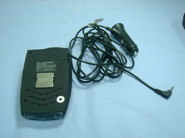
XXL-DGWM-GRD
Dec 16, 2009Radar Detector
Equipment Class
CRD - Part 15 Radar Detector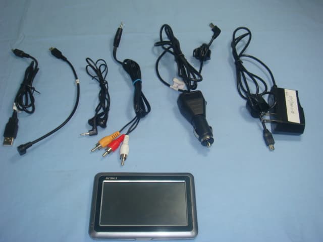
XXL-DGWM-PNDMA
Dec 13, 2009GPS Navigator
Equipment Class
DXX - Part 15 Low Power Communication Device Transmitter