XXL-DGWM-GRDRadar Detector
Dongguan Wanma Electronic and Technology Co., Ltd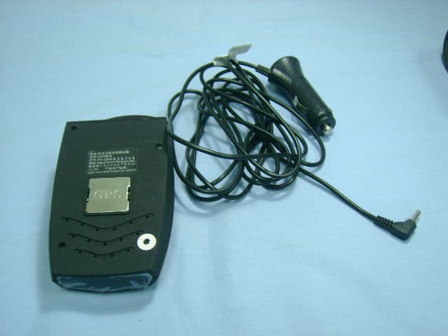
Click to zoom
Application Details
- Equipment Class
- CRD - Part 15 Radar Detector
- Date of Grant
- Dec 16, 2009
- Application Purpose
- Original Equipment
- Date of Application
- Dec 16, 2009
- Equipment Note
- Radar Detector
- Frequency Range
- 34080.00000000 - 35840.00000000
- Country
- China
Documents & Files
Document Text
Text extracted from the exhibit documents filed with the FCC. Open a document above to read the original.
Users Manual
User Manual of GRD-2010 Table of Contents 1. Summary 1.1 Features 1.2 Notice 1.3 Structure 1.4 Accessories 2. Basic Operation 2.1 Getting-Started 2.2 Power on/off 2.3 Installation 3. Program & Detection 3.1 Volume setting 3.2 Mode Selection 3.3 Sensitivity 3.4 Bands switch 3.5 Language Setting 3.6 Detection & alert 4. Maintenance & Service 4.1 Specification 4.2 Troubleshooting 4.3 Warranty SUMMARY Features 1. Chinese/English bilingual announcement free switch. 2. Super radar detection by high sensitive VCO waveguide. 3. Precise Radar frequency display 4. Clear digit display of 9 band Radar signal strength 5. Band switch- each band alert can be switched off/on separately 6. 3 levels of radar sensitivity adjustable- medium/high/ultrahigh 7. Urban/highway mode switch to eliminate false alerts 8. Full band detection(X, K, new K, Ku, Ka, new Ka, 6/8F, VG-2, 360°Laser) 9. Push button style power switch design 10. Volume adjustable by pressing keys. Notice 1. Please install the detector properly following the User Manual. A rule must be complied with is in whatever way the detector installed, it mustn’t impair the motorist’s view or increase the risk of an accident. 2. Depending on your car, the power supply of the cigarette lighter socket would be continuous or can be switched on/off by your ignition switch. So before you leaving the car, confirm the status of the detector. Do not leave the detector alone to be longtime running, this may lead to complete consumption of car battery or shorten the life of the detector. 3. Before leaving your car, always remember to conceal your detector in a safe place. To avoid the possibility of break-in theft or distortion of shape due to the heat of longtime exposure in the sun(sometime the temperature in car would be a hundred Celsius or above in Summer) 4. Use standard 12V DC power supply to the detector. Nothing should cover or overlie the detector while in use. Structure Item Name Note 1 Radar antenna For receiving radar signals 2 Mounting bracket slot To insert the kits of sucking cups or visor for mounting detector in car 3 Laser lens Receiving laser signal 4 ---- ---- 5 Bracket release button To lock or release the bracket to detector safely and quickly 6 12V DC power socket To connect the small end of the power cord for power supply 7 Speaker Where the announcements and alerts come from 8 Cooling holes For heat dissipation of detector 9 Function buttons 4 buttons of different functions,press single or 2 together to perform 10 Display screen Radar bands, signal strength etc. display Accessories Enclosed in package: Detector 12V DC car power cord Windshield mounting bracket U shaped visor mounting kit Strong magnet User manual QC certificate BASIC OPERATION Getting-Started To begin using your GRD-2010, simply follow these steps below: 1. Plug the small end of the power cord into the power socket at the right side of the detector, and plug the adapter of the other end into the car’s cigarette lighter socket. 2. Mount the detector on the windshield using the supplied windshield mounting brackets. 3. Press down the red button at the adapter to connect power. After the red indicator lights up, the icons in display screen all flash with 2 beeps. Then the announcement of current mode and sensitivity settings comes out and the detector comes into working condition. 3. Adjust the audio volume by pressing M2 and M3 button on the top case of the detector . Now GRD-2010 is ready to use. Please read the manual carefully to fully understand the operation and features. Power on/off The detector operates on 12 volts DC power only. The adapter of the power cord end has a fuse and a switch. NOTE: Please connect power to detector after the engine starts, to prevent the over-current shock while igniting. 1. To power the detector, just plug the small end of power cord into the socket at the right side of the detector, plug the adapter of the other end into Car cigarette lighter socket. Then press down the red button of the adapter. 2. To power off, long press M4 button. In case of an abnormal condition, just cut the power supply. (Not recommended ) Installation The manufacturer cannot anticipate the way the detector is installed. The ways showed bellow is most common; end users can make changes due to the real situation, but under the principles of never endangering driving safety. 1. Mounting on windshield. Depress the bracket releasing button on the top of the detector, then slide the mounting kit with sucking cups into the slot at the central top of radar antenna end (see STRUCTURE) Until the kit is locked by the slot. Mount the cups to windshield by pressing down to windshield glass. Be sure to make the glass and cups both are clean. The mounting position should have a clear view of the front. Bend the bracket if necessary, but slide the bracket off the detector before bending. 2. Mounting on the sun visor Depress the bracket releasing button and slide the short end of the U shaped bracket into the mounting slot until locked. Then mount the detector to the front edge of the visor board, make sure the radar antenna facing the front and bend the bracket if it grips the visor loosely. 3. Mounting on dashboard There is a strong magnet enclosed to mount your detector to the dashboard. Tear the plastic paper of the red side and stick the magnet at a right place of the dashboard. Simply put the detector on magnet. Don’t glue the magnet to dashboard if it is already strongly attracted. NOTE: No matter in whichever way the detector mounted, for the best detecting performance, never mount behind wipers, signs, strong metal films, etc. These will affect the receiving of radar and laser signal and result in the delay of critical warning time. The direction of the radar antenna should be horizontal forward or slightly down to the road, but never face to the sky or to the side of the car. PROGRAM & DETECTION Working Condition shows as below: Volume setting In working condition, pre…
Text truncated - open the document above for the full version.
External Photos
EXTERNAL PHOTOS
Internal Photos
INTERNAL PHOTOS
Operational Description
OPERATIONAL DESCRIPTION Device is a radar detector 1. Supply voltage: 12V from vehicle battery 2. Frequency of operation: Bands Frequency Sensitivity X-BAND 10.42~10.62GHZ±20MHZ 105±2dB Ku-BAND 13.32~13.54GHZ±20MHZ 105±2dB K-BAND 23.9~24.3GHZ±20MHZ 124±2dB Ka-BAND 34.1~35.82 GHZ±20MHZ 124±2dB VG-2 11.150±175MHZ / 3. Antenna type: Horn antenna 4. Antenna gain: 0dBi 5. Antenna connector: None (mounted on PCB) 6. Antenna photo: Antenna
Test Report
FCC ID:XXL-DGWM-GRD Report No.: 091121FIA01 1 Report Format Version 3.0.0 FCC ID TEST REPORT REPORT NO.: 091121FIA01 MODEL NO.: GRD-201X/GRD-35X RECEIVED: Nov. 11, 2009 TESTED: Nov. 11, 2009 ISSUED: Dec. 03, 2009 APPLICANT: Dongguan Wanma Electronic and Technology CO.,LTD ADDRESS: No.28, South DongShen Road, Zhangyang Fuda Industry Zone, Zhangmutou Town, Dongguan, Guangdong Province, P.R.C ISSUED BY: ADT (Shanghai) Corporation ADDRESS: 2F, Building C, No.1618, Yishan Rd., 201103, Shanghai, China This test report consists of 21 pages in total. It may be duplicated completely for legal use with the approval of the applicant. It should not be reproduced except in full, without the written approval of our laboratory. The client should not use it to claim product endorsement by TAF, A2LA or any government agencies. The test results in the report only apply to the tested sample. FCC ID:XXL-DGWM-GRD Report No.: 091121FIA01 2 Report Format Version 3.0.0 Table of Contents 1 CERTIFICATION............................................................................................. 3 2 SUMMARY OF TEST RESULTS .................................................................... 4 2.1 MEASUREMENT UNCERTAINTY...................................................................4 3 GENERAL INFORMATION ............................................................................. 5 3.1 GENERAL DESCRIPTION OF EUT ................................................................5 3.2 DESCRIPTION OF TEST MODES ..................................................................5 3.3 DESCRIPTION OF SUPPORT UNITS ............................................................6 4 EMISSION TEST ............................................................................................ 7 4.1 CONDUCTED EMISSION MEASUREMENT...................................................7 4.1.1 LIMITS OF CONDUCTED EMISSION MEASUREMENT ................................7 4.1.2 TEST INSTRUMENTS.....................................................................................7 4.1.3 TEST PROCEDURE........................................................................................8 4.1.4 DEVIATION FROM TEST STANDARD............................................................9 4.1.5 TEST SETUP...................................................................................................9 4.1.6 EUT OPERATING CONDITIONS ....................................................................9 4.1.7 TEST RESULTS ..............................................................................................9 4.2 RADIATED EMISSION MEASUREMENT......................................................10 4.2.1 LIMITS OF RADIATED EMISSION MEASUREMENT...................................10 4.2.2 TEST INSTRUMENTS................................................................................... 11 4.2.3 TEST PROCEDURE......................................................................................12 4.2.4 DEVIATION FROM TEST STANDARD..........................................................12 4.2.5 TEST SETUP.................................................................................................13 4.2.6 EUT OPERATING CONDITIONS ..................................................................13 4.2.7 TEST RESULTS ............................................................................................14 5 PHOTOGRAPHS OF THE TEST CONFIGURATION ................................... 18 6 PHOTOGRAPHS OF THE EUT.................................................................... 19 7 INFORMATION ON THE TESTING LABORATORIES.................................. 20 8 APPENDIX A – MODIFICATIONS RECORDERS FOR ENGINEERING CHANGES TO THE EUT BY THE LAB ........................................................ 21 FCC ID:XXL-DGWM-GRD Report No.: 091121FIA01 3 Report Format Version 3.0.0 1 CERTIFICATION PRODUCT: Radar Detector BRAND NAME: NA MODEL NO.: GRD-201X/GRD-35X APPLICANT: Dongguan Wanma Electronic and Technology CO.,LTD TESTED: Nov. 11, 2009 TEST ITEM: ENGINEERING SAMPLE STANDARDS: FCC Part 15, Subpart B, Class B ANSI C63.4-2003 The above equipment (Model: GRD-201X) has been tested by ADT (Shanghai) Corporation, and found compliance with the requirement of the above standards. The test record, data evaluation & Equipment Under Test (EUT) configurations represented herein are true and accurate accounts of the measurements of the sample’s EMC characteristics under the conditions specified in this report. PREPARED BY : , DATE:Dec. 03, 2009 (Ray Xue / Project Engineer) TECHNICAL ACCEPTANCE : , DATE:Dec. 03, 2009 Responsible for EMI (Joy Zhu / Manager) APPROVED BY : , DATE:Dec. 03, 2009 ( Wallace Pan / Director) FCC ID:XXL-DGWM-GRD Report No.: 091121FIA01 4 Report Format Version 3.0.0 2 SUMMARY OF TEST RESULTS The EUT has been tested according to the following specifications: Standard Test Type Result Remarks Conducted Test NA NA FCC Part 15, Subpart B, Class B Radiated Test PASS Meets Class B Limit Minimum passing margin is –4.78dB at 12138MHz 2.1 MEASUREMENT UNCERTAINTY Where relevant, the following measurement uncertainty levels have been estimated for tests performed on the EUT as specified in CISPR 16-4-2 Ed 1.0. This uncertainty represents an expanded uncertainty expressed at approximately the 95% confidence level using a coverage factor of k=2. This lab’s measurement uncertainty U Lab , is low than U Cispr , Table 1 – Values of U Cispr of CISPR 16-4-2 Ed. 1.0, therefore compliance is deemed to occur if no measured disturbance exceeds the disturbance limit. Measurement Value Conducted emissions 2.55 dB Radiated emissions 3.99 dB FCC ID:XXL-DGWM-GRD Report No.: 091121FIA01 5 Report Format Version 3.0.0 3 GENERAL INFORMATION 3.1 GENERAL DESCRIPTION OF EUT PRODUCT Radar Detector MODEL NO. GRD-201X/GRD-35X POWER SUPPLY 12V DC from the power adapter DATA CABLE SUPPLIED N/A NOTE: 1. Both GRD-201X and GRD-35X are supplied by the same PCB board with differ…
Text truncated - open the document above for the full version.
Test Setup Photos
RADIATED EMISSIONS TEST
Contact Information
Applicant
Wen Chang
Test Firm
BUREAU VERITAS ADT (Shanghai) CorporationZhaoqian YU
Technical Specifications
| # | Rule Parts | Frequency Range | Power Output |
|---|---|---|---|
| 5 | 15B | 34.08 GHz - 35.84 GHz | - |
Other Applications from Dongguan Wanma Electronic and Technology Co., Ltd
XXL-DGWM-AX16X
Feb 13, 2011Radar Detector
Equipment Class
CRD - Part 15 Radar Detector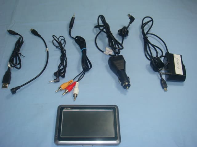
XXL-DGWM-PNDMA
Dec 13, 2009GPS Navigator
Equipment Class
DXX - Part 15 Low Power Communication Device Transmitter