XYOPCDQ880FBASICGSM dual band fixed wireless phone
Asiatelco Technologies Co.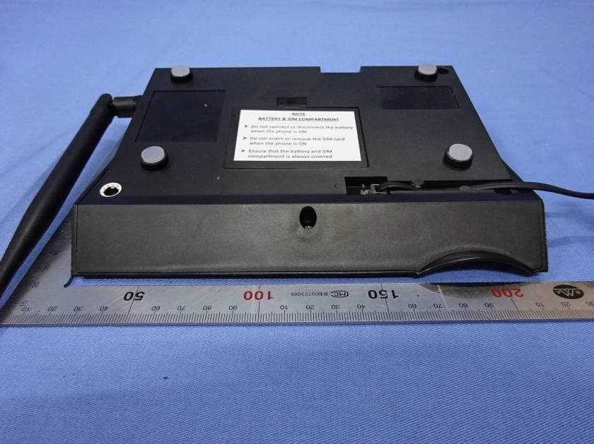
Click to zoom
Application Details
- Equipment Class
- PCB - PCS Licensed Transmitter
- Date of Grant
- Jul 29, 2015
- Application Purpose
- Original Equipment
- Date of Application
- Jul 29, 2015
- Equipment Note
- GSM dual band fixed wireless phone
- Frequency Range
- 1850.20000000 - 1909.80000000
- Company
- Asiatelco Technologies Co.
- Country
- China
Documents & Files
Document Text
Text extracted from the exhibit documents filed with the FCC. Open a document above to read the original.
Users Manual
User manual for Q880 R1.0 1 CONTENT 1. Overview First, thank you for your choosing of this GSM fixed wireless phone. We offer you this kind of GSM wireless communication terminal desktop products according to the market demand, with years of experience of developing and producing phones. The characteristics of the wireless access realize that the speech message sent anytime and anywhere, especially suitable for rural areas and the remote ares that it is unconvenient to use wire, etc. and any kind of indoor places for mobile communication. To ensure that all the function of the products can use normally, please read this detailed specification before use the products and note items as follows: z Please charge the battery for more than 16 hours when it is first charged. z For your safety, please do not use this product while driving. z In case of thunderstorms, please do not use this phone. z Please turn off it when on the plane, in the hospital, around dangerous goods, gas station and around fuel and chemicals or other dangerous goods. z Please turn off the phone when there are medical equipments that indicating not use wireless phone. This phone may interfere implanted heart pacemaker hearing aid and other medical implant equipment . z This may be interfered around TV, radio and computer and other electrical equipment, then the performance of phone may be affected. z Please turn off the phone then clean it. Please use a bit wet or anti-static cleaning cloth to clean the phone, do not use cleanser and other chemicals. z This product will generate magnetic field, do not put it around such as computer disk those kind of magnetic storage medium. User manual for Q880 R1.0 2 z Please do not let this product disposed in the strong sunshine, in case of heat. z Pleae avoid any knid of liquid running into the inside of the phone, in case of damaging. z Please do not rudely throw, put or beat the phone, or the circuit board inside will be damaged. z Before call and receive call, please take the local regulations about the use of wireless mobil phone into consideration, and pay attention when use it. z Please use the power adapter and battery designated by the manufacture, it will cause danger if use other power supply. z For the phone function upgrade continuously, it may be some discrepancy with specification during the actual use, sorry. z SAR: The device complies with RF specifications when the device used at 15mm far from your body. User manual for Q880 R1.0 3 2. Brief introduction Applicable to 850 MHZ /900 MHZ / 1800 MHZ /1900 MHZ public mobile communication network Single SIM single standby. Quick dial. Redial function. Phone book function. Hands-free function. Hand shank/Hands free volume digital control. 12ringtones/alarms. 10message ringtones & mute. Send & receive message, 200 message instore. 100 phone book LCD of date, time, signal strength and battery capacity. Instore, search, delete and callback 10 incoming calls and outgoing calls and missed call log. User manual for Q880 R1.0 4 3. Technical Conditions Environmental temperature: -10 0 C - 55 0 C Relative humidity (RH): ≤ 90% Atmospheric pressure: 86~106Kpa Operating frequency: GSM 850\ EGSM900\ DCS1800\PCS1900 MHz Operating voltage: AC220V, 50Hz,DC 5V 700mA Standby battery:chargable battery Stand-by time:more than 50 hours Continuous talking time:around 3 hours P.S.: stand-by time, continous talking time is determined by the local network condition. User manual for Q880 R1.0 5 4、Definition of keybord function: 1. MENU/OK key:In standby state, press this button to enter the main menu interface. In the menu operation mode, press this button execute the function on lower right corner of the screen function on the left lower screen. 2.CALLS ky:In standby state, press this button directly to enter the calls log. 3.BACK/DEL key: In standby state, press this button directly to phone book, press this button in the menu operation to return to previous menu. In the input condition, press this button to delete the cursor before a character. 3.ON/OFF key:when ON/OFF is open, long press ON/OFF key for start/close. 4.SMS key: In standby state, press this button directly to message menu. 5.↑key: In the operating menu, turn up, in standby state, press this button to missed calls menu. 6.↓key:In the operating menu, turn down, in standby state, press this button to received calls menu. 7.←key:During talking, turn down the voice, in the standby state, press this button to inbox menu, in the message input state, turn the cursor left forward. 8.→key:During talking state, turn up the voice, in the standby state, press this button to message edit menu, in the message input state, turn the cursor right forward. 9. Number key 10. Hands-free key:turn on/off the hands-free mode. 11.SEND/CALL key:once finish inputing number, press this button to call directly. In the stand-by state, press this button to show the all call log menu. 12.REDIAL key:In the stand-by state, press this button to dial the number that has been dialed last time. 13. C.LIST key: In the stand-by state, press this button to show the call history menu. User manual for Q880 R1.0 6 5. Install and connect 5-1 Install SIM card 1. Open the cover of SIM card 2. Open SIM card deck, insert SIM card according to the direction of the gap. 3. Tire SIM card deck, let the metal of SIM card connect with the card deck well, then close the deck of SIM card. NOTE: z Inserting or pulling out SIM card is absolutely forbidden when it is turned on, or SIM card may be damaged. z In case of loss or damage of information in card,please back up in time, and avoid touching the metal are,and put SIM card away from electromagnetic. Once SIM card is damaged, it is impossible for you to enter GSM network. z In some ares, th phones have built-in SIM card, it is unnecessary to operate this. 5-2 Connect external power 5-3 Connect hand shank Connect the hand shank to the left 616 co…
Text truncated - open the document above for the full version.
Cover Letter(s)
Asiatelco Technologies Co. 289 Bisheng Road, Building 8, 3F, Zhangjiang Hi-Tech Park, Pudong, Shanghai 201204, China DATE :2015-7-20 Nemko Canada Inc 303 River Road Ottawa, Ontario, Canada K1V 1H2 Attn: Director of Certification Authority to Act as Agent On our behalf, I appoint Hank Yan of Global United Technology Services Co., Ltd. 2nd Floor, Block No.2, Laodong Industrial Zone, Xixiang Road Baoan District Shenzhen Guangdong to act as our agent in the preparation of this application for equipment certification. I certify that submitted documents properly describe the device or system for which equipment certification is sought. I also certify that each unit manufactured, imported or marketed, as defined in the Federal Communications Commission’s regulations will have affixed to it a label identical to that submitted for approval with this application. For instances where our authorized agent signs the application for certification on our behalf, I acknowledge that all responsibility for complying with the terms and conditions for certification, as specified by Nemko Canada Inc, still resides with Asiatelco echnologies Co. and 289 Bisheng Road, Building 8, 3F, Zhangjiang Hi-Tech Park, Pudong, Shanghai 201204, China Dated this / Day of 7/20/2015 / Agency agreement expiration date: 7/20/2016 By: Ranran Zhou Signature Printed Title: Project Manager On behalf of : Asiatelco Technologies Co. Telephone: +8 6-21-51688806
Cover Letter(s)
Asiatelco Technologies Co. 289 Bisheng Road, Building 8, 3F, Zhangjiang Hi-Tech Park, Pudong, Shanghai 201204, China 2015-7-15 Equipment Autorisation Division Federal Communications Commission 7435 Oakland Mills Road Columbia, MD 21046 FCC ID: XYOPCDQ880FBASIC Product Name: GSM dual band fixed wireless phone Request for Confidentiality Pursuant to Sections 0.457 and 0.459 of the commissions rules, we hereby request that the following documents be held confidential: Schematics Block diagram Operational Description Tune up Procedure These materials contain trade secrets and proprietary information and are not customarily released to the public. The public disclosure of this information might be harmful to the company and provide unjustified benefits to our competitors. Dated this 7/20/2015 By: Ranran Zhou Signature Printed Title: Project Manager On behalf of : Asiatelco Technologies Co. Telephone: +8 6-21-51688806
ID Label/Location Info
1. IMEI Label 2. PositionA As below:
RF Exposure Info
Report No. 2015SAR318 Page 2 / 75 V1.0 Standards Conclusion Localized Specific Absorption Rate (SAR) of this equipment has been measured in all cases requested by the relevant standards above. Maximum localized SAR is below exposure limits as well. Applicable Limit Regulations ANSI/IEEE C95.1-2005 Safety Levels with Respect to Human Exposure to Radio Frequency Electromagnetic Fields. 3 kHz to 300 GHz ANSI/IEEE C95.3-2002 Recommended Practice For Measurements and Computations of Radio Frequency Electromagnetic Fields with Respect to Human Exposure to such Fields. 100 kHz-300 GHz Applicable Standards IEEE Std 1528™-2013: IEEE Recommended Practice for Determining the Peak Spatial-Average Specific Absorption Rate (SAR) in the Human Head from Wireless Communications Devices: Measurement Techniques KDB865664 D01v01r03: SAR Measurement Requirements for 100 MHz to 6 GHz KDB447498 D01v05r02: Mobile and Portable Device RF Exposure Procedures and Equipment Authorization Polices Report No. 2015SAR318 Page 3 / 75 V1.0 Change History Version Change Contents Author Date V1.0 First edition Chen Qiang 2015-07-14 Note: The last version will be invalid automatically while the new version is issued. Report No. 2015SAR318 Page 4 / 75 V1.0 CONTENTS: STANDARDS ............................................................................................................................. 2 CONCLUSION ........................................................................................................................... 2 CHANGE HISTORY ................................................................................................................... 3 1. STATEMENT OF COMPLIANCE ........................................................................................ 6 2. ADMINISTRATIVE INFORMATION ....................................................................................... 7 2.1 PROJECT INFORMATION ........................................................................................................................... 7 2.2 TEST LABORATORY INFORMATION ........................................................................................................... 7 2.3 TEST ENVIRONMENT ................................................................................................................................ 7 3. CLIENT INFORMATION ........................................................................................................ 8 3.1 APPLICANT INFORMATION ........................................................................................................................ 8 3.2 MANUFACTURER INFORMATION ............................................................................................................... 8 4. EQUIPMENT UNDER TEST (EUT) AND ACCESSORY EQUIPMENT (AE) ......................... 9 4.1 INFORMATION OF EUT ............................................................................................................................. 9 4.2 IDENTIFICATION OF EUT ........................................................................................................................ 10 4.3 IDENTIFICATION OF AE ........................................................................................................................... 10 5.OPERATIONAL CONDITIONS DURING TEST ................................................................. 11 5.1 GENERAL DESCRIPTION OF TEST PROCEDURES .................................................................................... 11 5.2 GSM TEST CONFIGURATION ................................................................................................................. 11 6. SAR MEASUREMENTS SYSTEM CONFIGURATION ........................................................ 12 6.1 SAR MEASUREMENT SET-UP ................................................................................................................ 12 6.2 DASY5 E-FIELD PROBE SYSTEM ......................................................................................................... 13 6.2.1 Es3DV3 Probe Specification ...................................................................................................... 13 6.2.2 E-field Probe Calibration ............................................................................................................. 14 6.3 OTHER TEST EQUIPMENT ...................................................................................................................... 15 6.3.1 Device Holder for Transmitters .................................................................................................. 15 6.3.2 Phantom ........................................................................................................................................ 15 6.4 SCANNING PROCEDURE ......................................................................................................................... 16 6.5 DATA STORAGE AND EVALUATION .......................................................................................................... 17 6.5.1 Data Storage ................................................................................................................................ 17 6.5.2 Data Evaluation by SEMCAD .................................................................................................... 18 6.6 SYSTEM CHECK ...................................................................................................................................... 20 6.7 EQUIVALENT TISSUES ............................................................................................................................ 20 7. SUMMARY OF TEST RESULTS ......................................................................................... 22 7.1 CONDUCTED OUTPUT POWER MEASUREMENT ......................................................... 22 7.1.1 SUMMARY ...............................................................................................…
Text truncated - open the document above for the full version.
Test Report
Global United Technology Services Co., Ltd. Report No.: GTSE15060117101 1 Cover Page FCC Report (GSM) Applicant: Asiatelco Technologies Co. Address of Applicant: 289 Bisheng Road, Building 8, 3F, Zhangjiang Hi-Tech Park, Pudong, Shanghai 201204, China Equipment Under Test (EUT) Product Name: GSM dual band fixed wireless phone Model No.: Q880 FBASIC Trade Mark: PCD FCC ID: XYOPCDQ880FBASIC Applicable standards: FCC CFR Title 47 Part 2: 2014 FCC CFR Title 47 Part22 Subpart H: 2014 FCC CFR Title 47 Part24 Subpart E: 2014 Date of sample receipt: June 29, 2015 Date of Test: June 30-July 03, 2015 Date of report issued: July 03, 2015 Test Result : PASS * * In the configuration tested, the EUT complied with the standards specified above. Authorized Signature: Robinson Lo Laboratory Manager This report details the results of the testing carried out on one sample. The results contained in this test report do not relate to other samples of the same product and does not permit the use of the GTS product certification mark. The manufacturer should ensure that all products in series production are in conformity with the product sample detailed in this report. This report may only be reproduced and distributed in full. If the product in this report is used in any configuration other than that detailed in the report, the manufacturer must ensure the new system complies with all relevant standards. Any mention of GTS or testing done by GTS in connection with, distribution or use of the product described in this report must be approved by GTS in writing. This document cannot be reproduced except in full, without prior written approval of the Company. Any unauthorized alteration, forgery or falsification of the content or appearance of this document is unlawful and offenders may be prosecuted to the fullest extent of the law. Unless otherwise stated the results shown in this test report refer only to the sample(s) tested and such sample(s) are retained for 90 days only. Report No.: GTSE15060117101 2 Version Version No. Date Description 00 July 03, 2015 Original Prepared By: Date: July 03, 2015 Project Engineer Check By: Date: July 03, 2015 Reviewer Global United Technology Services Co., Ltd. Project No.: GTSE150601171RF Room 301-309, 3th Floor, Block A, Huafeng Jinyuan Business Building, No. 300 Laodong Industrial Zone,Xixiang Road, Baoan District, Shenzhen 518102 Telephone: +86 (0) 755 2779 8480 Fax: +86 (0) 755 2779 8960 Page 2 of 39 Report No.: GTSE15060117101 3 Contents Page 1 COVER PAGE .......................................................................................................................................... 1 2 VERSION .................................................................................................................................................. 2 3 CONTENTS .............................................................................................................................................. 3 4 TEST SUMMARY ..................................................................................................................................... 4 5 GENERAL INFORMATION ...................................................................................................................... 5 5.1 CLIENT INFORMATION .......................................................................................................................... 5 5.2 GENERAL DESCRIPTION OF EUT ......................................................................................................... 5 5.3 RELATED SUBMITTAL(S) / GRANT (S) ................................................................................................... 7 5.4 TEST METHODOLOGY .......................................................................................................................... 7 5.5 TEST FACILITY .................................................................................................................................... 7 5.6 TEST LOCATION .................................................................................................................................. 7 6 TEST INSTRUMENTS LIST ..................................................................................................................... 8 7 SYSTEM TEST CONFIGURATION ......................................................................................................... 9 7.1 TEST MODE ........................................................................................................................................ 9 7.2 CONFIGURATION OF TESTED SYSTEM .................................................................................................. 9 7.3 CONDUCTED PEAK OUTPUT POWER .................................................................................................. 10 7.4 OCCUPY BANDWIDTH ........................................................................................................................ 11 7.5 MODULATION CHARACTERISTIC ............................................................................................... 15 7.6 OUT OF BAND EMISSION AT ANTENNA TERMINALS ................................................................................ 15 7.7 ERP, EIRP MEASUREMENT .............................................................................................................. 19 7.8 FIELD STRENGTH OF SPURIOUS RADIATION MEASUREMENT .................................................................. 23 7.9 FREQUENCY STABILITY V.S. TEMPERATURE MEASUREMENT ................................................................ 27 7.10 FREQUENCY STABILITY V.S. VOLTAGE MEASUREMENT ........................................................................ 29 8 TEST SETUP PHOTO ............................................................................................................................ 31 9 EUT CONSTRUCTIONAL DETAILS ...............................................................…
Text truncated - open the document above for the full version.
Test Setup Photos
Radiated Emission
Test Setup Photos
Report No. 2015SAR318 Page 1 / 8 V1.0 ANNEX D: Picture of antennas Picture of DUT’s antenna Report No. 2015SAR318 Page 2 / 8 V1.0 ANNEX E: Definition of Test Positions POSITION OF BODY antenna Horizontal TOWARDS GROUND WITH 15mm DISTANCE POSITION OF BODY antenna Horizontal front WITH 15mm DISTANCE Report No. 2015SAR318 Page 3 / 8 V1.0 POSITION OF BODY antenna Horizontal back 15mm DISTANCE POSITION OF BODY antenna Horizontal right side WITH 15mm DISTANCE Report No. 2015SAR318 Page 4 / 8 V1.0 POSITION OF BODY antenna vertical towards phantom WITH 15mm DISTANCE POSITION OF BODY antenna vertical towards ground WITH 15mm DISTANCE Report No. 2015SAR318 Page 5 / 8 V1.0 POSITION OF BODY antenna vertical back WITH 15mm DISTANCE POSITION OF BODY antenna vertical right side WITH 15mm DISTANCE Report No. 2015SAR318 Page 6 / 8 V1.0 ANNEX F: Photograph EUT Report No. 2015SAR318 Page 7 / 8 V1.0 Travel Adaptor Report No. 2015SAR318 Page 8 / 8 V1.0 battery ------------------------------------------END OF REPORT----------------------------------------------------
Contact Information
Applicant
Ella Chen(Certification Manager)
Test Firm
Global United Technology Service Co., LtdRobinson Lo
Technical Specifications
| # | Rule Parts | Frequency Range | Power Output | Emission | Tolerance |
|---|---|---|---|---|---|
| 2 | 24E | 1.85 GHz - 1.91 GHz | 940.00 mW | 246KGXW | 0.07 ppm |
Other Applications from Asiatelco Technologies Co.
XYO-AT16N
Jan 14, 2026GPS TRACKER
Equipment Class
JBP - Part 15 Class B Computing Device Peripheral
XYO-AN99
Dec 22, 2025GPS TRACKER
Equipment Class
JAB - Part 15 Class B Digital Device
XYO-LM190
Dec 18, 2025Wi-Fi Halow Module
Equipment Class
JAB - Part 15 Class B Digital DeviceXYO-RE600
Aug 08, 20244G/5G Wi-Fi Router
Equipment Class
JAB - Part 15 Class B Digital Device
XYO-AN95
Mar 18, 2024AN95
Equipment Class
JAB - Part 15 Class B Digital Device