XZF-CM8022.4GHz Wireless Camera
SHENZHEN LYD TECHNOLOGY CO.LTD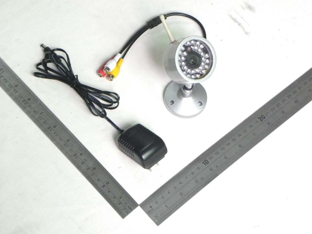
Click to zoom
Application Details
- Equipment Class
- DXX - Part 15 Low Power Communication Device Transmitter
- Date of Grant
- Mar 21, 2011
- Application Purpose
- Original Equipment
- Date of Application
- Mar 21, 2011
- Equipment Note
- 2.4GHz Wireless Camera
- Frequency Range
- 2414.00000000 - 2468.00000000
- Country
- China
Documents & Files
Document Text
Text extracted from the exhibit documents filed with the FCC. Open a document above to read the original.
Users Manual
RC431 USB Wireless Receiver User Manual Thank you for using our wireless USB receiver, please read the following content carefully before using, it will help you make better use of this product. Introduction RC431 wireless USB receiver works in ISM Band: 2400 ~ 2483MHz to receive wireless camera audio and video signals and displays the received image signal via PC. With our “LYD Monitoring System” software, you can capture the image and video you are watching, and play back the data recorded. It can also be used as a regular receiver to convert the Video & Audio signals to normal monitor/TV. A simple switch from TV to AV on your television enables you to enjoy its capability for entertainment, monitoring and security purposes. Basic Specification z Support Windows XP & VISTA z Support USB2.0 z Video and Audio z Support remote monitoring and controlling by third-party software via PC, support Internet video telephone z ISM Frequency Band:2400~2483MHz z Receiving Frequency:CH1=2414MHz,CH2=2432MHz, CH3=2450MHz,CH4=2468MHz z Receiving Sensitivity: -85 dbm z IF frequency: 480MHz z Video Output amplitude:1Vp-p z Audio Output amplitude: 2.5Vp-p(Max) z High-speed image compression processing, display speed:30fp/s z Resolution: 640*480; 320*240 z Power Supply: PC Mode: USB power, no power adapter; Monitor / TV Model: DC5V/500mA z Dimension: 120x99x30mm z Operating temperature: -10~50°C Diagram: Antenna Channel button (ON/ OFF) Channel Indicator Audio Video USB Port Installation Monitor / TV mode: 1. Connect the wireless cameras with the configured power adaptor and power on. 2. If two or more wireless cameras are installed at the same time, please keep a distance of 2 meters or more between the two wireless cameras, as well as between cameras and receiver too. Otherwise there might be signal interference between them so that will influence the image quality. 3. Turn the antenna of RC431 and make the antenna vertical upward in order to ensure the best reception. 4. Connect one end of the AV cable to the RC431's AUDIO and VIDEO output jack ,and the other side to the monitor / TV AUDIO and VIDEO input jack. 5. Insert the AC input plug of the power adapter (DC5V/500mA) into electricity socket, insert DC output plug into RC431 USB socket. Turn on the main power, and then you will see the red mark on the receiver. 6. Turn on the monitor / TV power supply, change the monitor / TV to AV mode. 7. RC431 button operation: 1). Power on: In the off state, one press on the button enables the receiver power on and the channel indicator LED turns on. 2). Switching channels: In the operation state, one press on the button enables to receiver jump into next channel. 3). Power off: In the operation state, press the button and keep more than 1 second. Release the button when the LED indicator turns off. 8. Adjust the camera lens if the image is not clear. 9. Adjust TV brightness, contrast, and color of the monitor to obtain the best quality images. Speed DVR user manual Welcome to use Speed Soft Speed DVR ™. This video surveillance software is designed to meet your demands for security and surveillance purposes. Speed DVR provides security and protection for workplace, house, baby room, car, garage and so on. Speed DVR enables your computer to become a powerful monitoring system. Speed DVR supports remote monitoring in real-time and Multi-cameras displaying. Speed DVR enables to capture camera movements and save multi-media file formats in computer. Search and manage the recorded data easily. Speed DVR function Speed DVR software Key features. • Motion detection • ASF code • Remote Capture video content • Intelligent archiving video surveillance • Multi-Camera View • cameras • Quick search • Recorded data and files management • Strong reliability Interface Basics This section describes the various interfaces of the Speed DVR briefly. Speed DVR Main window Speed DVR user interface contains Control panel part, Video display area part and Right-click menu part, Speed DVR enables you to manage recorded data and any content easily. Use Speed DVR Control Panel, you can easily access to all common functions program. The following table describes all the features of Speed DVR control panel: ICON Function Description Exit Exit Speed DVR. Record Using the current camera to start recording Play/Pause Play or pause when recording. STOP STOP playing Snapshot Capture the video picture Zoom and Panorama Enlarge or minimize the image viewing area. Alarm Enable or disable the alarm Settings Display Settings dialog Help Be on the screen with instant access to information about how to use Speed DVR detailed information and instructions Display area Shows the status of the process of recording, such as the camera input source and recording time Volume Control Drag the slider to increase or decrease playback volume. Click the speaker icon to mute Slipper block Displays the current playback status. Drag the slider, the video moves to a specific location Backward and forward Forward or backward Video Camera Select a camera button, and watch or record the image Multi-Camera Mode Support converting to single-or multi-camera display window Open the file Open the recorded files, and play. Right -Click Menu Speed DVR Right -Click Menu include following items: Play:Start playing Pause: Pause playback of recorded files Stop: Stop playing Recording:start or stop recording Camera:Select a camera to play Play files:Play recorded files Capture picture:Capture video picture Full screen:Playing video in full screen Multi-frame:display 4 pictures in one screen Alarm:Start or cancel alarm function Front-end display:Window displays at the top of all windows Scheduled Tasks: Scheduled Tasks dialog is open Settings:Open the Settings dialog Registration: Software Registration Check for updates: networking check for new versions Help:Show Help Document Regarding: the software version information and instruction Exit:Exit Speed DVR Introduction Before using S…
Text truncated - open the document above for the full version.
Cover Letter(s)
SCS-F18: Project and Product Certification Representative Authorization Letter Page 1 of 2 Rev 2.0 2206 Ringwood Avenue San Jose, CA 95131 Tel: 408-526-1188 Fax: 408-526-1088 Email: [email protected] Project and Product Certification Representative Authorization Letter Revision History Reason for Amendment (current / obsolete) From To Approved Date Initial Release (current) 1.0 1.0 Nov-14-2006 Revised wording (current) 1.0 2.0 Sept–25-2007 SCS-F18: Project and Product Certification Representative Authorization Letter Page 2 of 2 Rev 2.0 SHENZHEN LYD TECHNOLOGY CO., LTD. Date:2011-03-15 To: SIEMIC, INC. 2206 Ringwood Avenue, San Jose, CA 95131 USA Dear Sir/Madam, Re: Project and Product Certification Representative Authorization Letter We, SHENZHEN LYD TECHNOLOGY CO., LTD. hereby authorize SIEMIC, INC. to act as a Certification Body for certifying for the following project(s): Product: 2.4GHz Wireless Camera (M/N: CM802) We affirm that between SIEMIC and SHENZHEN LYD TECHNOLOGY CO., LTD., any difference in understanding, including test plan, measurement methods, applicable standards and relevant procedures and processes have been resolved prior to commencement of testing activities. Signature Mingsheng Deng Manager SHENZHEN LYD TECHNOLOGY CO., LTD. Building A, Cunnan Industrial Estate, Shuidou Laowei, Longhua Town, Bao’an District, Shenzhen, China.
External Photos
General Appearance of the EUT
ID Label/Location Info
FCC ID: XZF-CM802 This device complies with part 15 of the FCC Rules. Operation is subject to the following two conditions: (1) this device may not cause harmful interference, and (2) this device must accept any interference received, including interference that may cause undesired operation.
ID Label/Location Info
FCC ID Lable Location On EUT
Internal Photos
Antenna
Operational Description
Operation Description High Frequency Part The High Frequency Signal which is received by the Antenna gets through the RF AMP, IF AMP, PLL VCO, and then decode the Baseband Signal by wideband FM, and output the Video & Audio signal after amplifying filter. Low Frequency Part The signal which is output from the High Frequency part is divided into two parts. One of which is output to the MONITOR directly after amplifying, while the other enters V C0257 to realize Analogue/Digital Convert. The Digital A/V signals are being converted and comp ressed by the compression chip via multiple switchers. The Data being compressed is transferred to the PC via USB Port, and it is the PC to realize deco mpression and display.
Schematics
U1 PC1030N PC1030N_CLCC40 R4 10R C3100nF C4100nF C5 NC C10 30pF C6 20pF D2 1SS355 SOD323(ROHM) C1 10uF Y1 27MHz C2100nF R9 NC R12 10K R13 10K R16 0R R2 1M R1047K R18 75R/100R R5 47K R3 1K5 J1 Wireless J4 MIC in J5 12V in J6 Audio/Video J7 NC/Power/AV C9 1uF R8 4K7 R19 470K C11 220P C12 100nF R215K6 C13 100nF U3 78L08 C14 100nF C15 100nF U5 78L05 R15 4K7 C17100pF C21 100nF R24 47K U6 AME8800CEFT R26 33R U8-A UMX1N U8-B UMX1N R272K R28 NC R2922RR3075R LENS_HOLE U4 78L05 C22100nF C19 47uF J3 IR U7 78L08 C7 100nF C23 22uF C20 22uF C25 100nF C27 100nF R6 10K R7 4K7 R11 4K7 U13 PIC12F509 Q1 2N3904 C8 NC R1 2K7 C24 1nF R14 10K R17 10K R20 10K R22 NC R23 NC R31 200R D1 1N4148 REXT VDD2V8 VDD2V8 VDD1V8 STDBY RSTB N/PMIR X1X2 RFAUDIO VIDEO VDD2V8 AUDIO +12V VDD2V8 VDD2V8 VDD2V8 VDD2V8 VDD2V8 VDD1V8 +12V RFAUDIO RFVIDEO +8V +5V RF+5V VDD2V8 RFVIDEO VIDEO RF+5V VDD2V8 SSDA SSCL STDBYRSTB SSDA SSCL AUDIO CM802 Lizequan 1 1of Sheet Date: Rev Document Number SizeTitle 2010-3-29 B A BCD 5 4 3 2 1 DCB A 1 2 3 4 5 1.0 Drawing : 2010.3.4 R18 PC1030N 75R R18 PC1030D 100R 1 HSYNC 2 D6 3 D7 4 VSYNC 5 RSTB 6 AVDD 7 NC 8 NC 9 AGND 10 STDBY 11 CVDD 12 CP 13 CN 14 AVDD 15 AGND 16 CGND 17 REXT 18 TE 19 D0 20 D1 21 D2 22 D3 23 X1 24 X2 25 PCLK 26 LEDCTL0 27 MOTION 28 CADDR0 29 CADDR1 30 DVDD 36 RSCL 35 RSDA 34 LEDCTL1 33 HVDD 32 HGND 31 DGND 40 D5 39 D4 38 SSDA 37 SSCL 123456 12 1212 1234 OUT GND IN OUT GND IN IN OUT GND 2 6 1 5 3 4 OUT GND IN 12 OUT GND IN 1 VDD 2 GP5/OSC1/CLKIN 3 GP4/OSC2 4 GP3/MCLR/VPP 5 GP2/T0CKI 6 GP1/ICSPCLK 7 GP0/ICSPDAT 8 VSS B C E
Test Report
DONGGUAN EMTEK CO., LTD. REPORT NO.: KAD110124045E FCC ID: XZF-CM802 DATE: 03/15/2011 Page 1 of 29 ELECTROMAGNETIC EMISSIONS COMPLIANCE REPORT INTENTIONAL RADIATOR CERTIFICATION TO FCC PART 15 SUBPART B &C REQUIREMENT OF 2.4GHz Wireless Camera MODEL No.: CM802 BRAND NAME: LYD FCC ID: XZF-CM802 REPORT NO: KAD110124045E ISSUE DATE: March 15, 2011 Prepared for SHENZHEN LYD TECHNOLOGY CO., LTD. Building A, Cunnan Industrial Estate, Shuidou Laowei, Longhua Town, Bao’an District, Shenzhen, China. Prepared by DONGGUAN EMTEK CO., LTD. No.281, Guantai Road, Nancheng District, Dongguan, Guangdong, China TEL: 86-769-22807078 FAX: 86-769-22807079 DONGGUAN EMTEK CO., LTD. REPORT NO.: KAD110124045E FCC ID: XZF-CM802 DATE: 03/15/2011 Page 2 of 29 VERIFICATION OF COMPLIANCE Applicant: SHENZHEN LYD TECHNOLOGY CO., LTD. Building A, Cunnan Industrial Estate, Shuidou Laowei, Longhua Town, Bao’an District, Shenzhen, China. Product Description: 2.4GHz Wireless Camera Brand Name: N/A Model Number: CM802 File Number: KAD110124045E Date of Test: January 25, 2011 to March 15, 2011 We hereby certify that: The above equipment was tested by DONGGUAN EMTEK CO., LTD. The test data, data evaluation, test procedures, and equipment configurations shown in this report were made in accordance with the procedures given in ANSI C63.4 (2009) and the energy emitted by the sample EUT tested as described in this report is in compliance with conducted and radiated emission limits of FCC Rules Part 15.249. The test results of this report relate only to the tested sample identified in this report. Approved By Sam Lv / Q.A. Manager DONGGUAN EMTEK CO., LTD. DONGGUAN EMTEK CO., LTD. REPORT NO.: KAD110124045E FCC ID: XZF-CM802 DATE: 03/15/2011 Page 3 of 29 Ta b l e o f C o n t e n t s 1. GENERAL INFORMATION ........................................................................................................... 4 1.1 PRODUCT DESCRIPTION........................................................................................................................... 4 1.2 RELATED SUBMITTAL(S) / GRANT (S) ..................................................................................................... 5 1.3 TEST METHODOLOGY.............................................................................................................................. 5 1.4 SPECIAL ACCESSORIES............................................................................................................................ 5 1.5 EQUIPMENT MODIFICATIONS.................................................................................................................. 5 1.6 TEST FACILITY........................................................................................................................................ 6 2. SYSTEM TEST CONFIGURATION .............................................................................................. 7 2.1 EUT CONFIGURATION............................................................................................................................. 7 2.2 EUT EXERCISE........................................................................................................................................ 7 2.3 TEST PROCEDURE.................................................................................................................................... 7 2.4 LIMITATION............................................................................................................................................. 7 2.5 CONFIGURATION OF TESTED SYSTEM..................................................................................................... 9 3. SUMMARY OF TEST RESULTS ................................................................................................. 10 4. DESCRIPTION OF TEST MODES............................................................................................... 10 5. CONDUCTED EMISSIONS TEST ............................................................................................... 11 5.1 MEASUREMENT PROCEDURE:................................................................................................................ 11 5.2 TEST SET-UP (BLOCK DIAGRAM OF CONFIGURATION) ....................................................................... 11 5.3 MEASUREMENT EQUIPMENT USED: ...................................................................................................... 11 5.4 MEASUREMENT RESULT:....................................................................................................................... 11 5.5 CONDUCTED MEASUREMENT PHOTOS: ................................................................................................ 14 6. RADIATED EMISSION TEST ......................................................................................................15 6.1 MEASUREMENT PROCEDURE................................................................................................................. 15 6.2 TEST SET-UP (BLOCK DIAGRAM OF CONFIGURATION) ....................................................................... 16 6.3 MEASUREMENT EQUIPMENT USED: ...................................................................................................... 17 6.4 OUT OF BAND RADIATED MEASUREMENT RESULT.............................................................................. 17 6.5 RADIATED MEASUREMENT PHOTOS:.................................................................................................... 21 7. BAND EDGE .................................................................................................................................... 22 8. ANTENNA APPLICATION ........................................................................................................... 24 8.1 ANTENNA REQUIREMENT...................................................................................................................... 24 DONGGUAN EMTEK CO., LTD. REPORT NO.: KAD11…
Text truncated - open the document above for the full version.
Test Setup Photos
Conducted Emission Setup Photos Radiated Emission Setup Photos
Contact Information
Applicant
Deng Mingsheng
Test Firm
EMTEK (DONGGUAN) CO.,LTDSam Lv
Technical Specifications
| # | Rule Parts | Frequency Range | Power Output |
|---|---|---|---|
| 1 | 15C | 2.41 GHz - 2.47 GHz | - |
Other Applications from SHENZHEN LYD TECHNOLOGY CO.LTD

XZF-SM209DT
Aug 02, 2012Digital Wireless Camera and Receiver
Equipment Class
DSS - Part 15 Spread Spectrum Transmitter
XZF-SM703DT
Aug 01, 2012Digital Wireless Camera and Receiver
Equipment Class
DSS - Part 15 Spread Spectrum Transmitter
XZF-CM387
Apr 11, 2011DIGITAL WIRELESS CAMERA
Equipment Class
DXX - Part 15 Low Power Communication Device Transmitter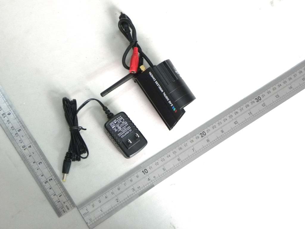
XZF-CM701
Apr 11, 2011DIGITAL WIRELESS CAMERA
Equipment Class
DXX - Part 15 Low Power Communication Device Transmitter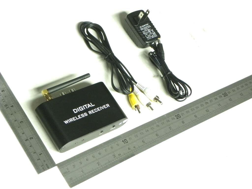
XZF-RC460
Mar 27, 2011DIGITAL WIRELESS RECEIVER
Equipment Class
DXX - Part 15 Low Power Communication Device Transmitter