Y3D-RED4SFFRFID Module
Phychips Inc.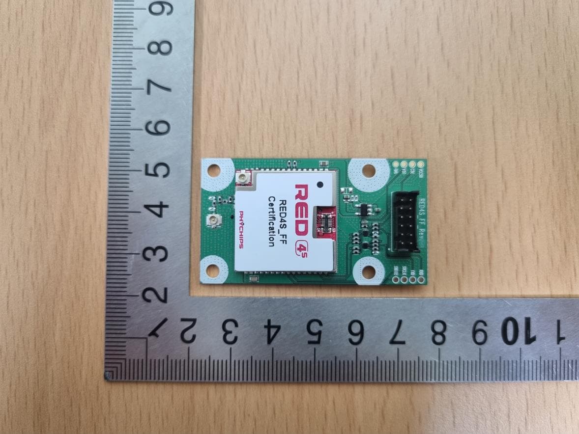
Click to zoom
Application Details
- Equipment Class
- DSS - Part 15 Spread Spectrum Transmitter
- Date of Grant
- Jul 18, 2023
- Application Purpose
- Original Equipment
- Date of Application
- Jul 18, 2023
- Equipment Note
- RFID Module
- Frequency Range
- 917.10000000 - 926.90000000
- Company
- Phychips Inc.
- Country
- South Korea
Documents & Files
Document Text
Text extracted from the exhibit documents filed with the FCC. Open a document above to read the original.
Users Manual
RED4S_FF User’s Manuals 25 July 2023 2 of 10 RED4S_FF User’s Manuals Contents 1 Pin Description .................................................................................................................................. 3 1.1 RED4S_FF Pin Description ................................................................................................................. 3 2 Operation Method .............................................................................................................................. 4 2.1 Power Supply ...................................................................................................................................... 4 2.2 UART ................................................................................................................................................... 4 2.3 RF In/Out ............................................................................................................................................. 4 2.4 GUI Control ......................................................................................................................................... 4 3 Specification ...................................................................................................................................... 8 25 July 2023 3 of 10 RED4S_FF User’s Manuals 1 Pin Description 1 2 43 56 78 910 1112 Figure 1 Pin map of RED4S_FF 1.1 RED4S_FF Pin Description No. Pin Name Description 1,2,6,11,12 GND GND 3 RXD UART Rx(3.3V) 4 VCC50 VCC 5.0V : supply power to RED4S_FF 5 TXD UART Tx(3.3V) 7,10 NC No connection 8 VIO Supply power to Level shifter IC (3.3V) 9 CSE Chip select enable(3.3V) 25 July 2023 4 of 10 RED4S_FF User’s Manuals 2 Operation Method 2.1 Power Supply DC power to operate RED4S_FF is to supply for internal LDO. 2.2 UART The serial interface is assigned with two wires. RS232_TX is for receiving command from host and RS232_RX is for transmitting response to host. Pin connection is shown as below figure. TXDx RXDx GND RED4S_FF Host MCU TXD RXD GND Figure 2 Host MCU Connection 2.3 RF connector RF connector is optimized with 50ohm impedance. Connector’s part number is DF11-12DP-2DSA(Hirose co.,LTD) 2.4 GUI Control The RED Utility helps the user to start working with RED DK RFID reader quickly. Follow below steps to run GUI. Windows Start button Program Menu RED Utility_vX.X.X Figure 3 RED Utility_vX.X.X 25 July 2023 5 of 10 RED4S_FF User’s Manuals 2.4.1 Mode Change RED Utility provides two view modes. User can select view mode depending on purpose of use between Basic View Mode and Extended View Mode. Figure 4 Basic View Mode To change View Mode, click the extension button marked red in Figure 4 above. Figure 5 Extended View Mode Always use Extended View Mode for measurement. 25 July 2023 6 of 10 RED4S_FF User’s Manuals 2.4.2 RED4S_FF Connection If hardware connection is valid, RED utility connect module REDx automatically. If utility cannot connect hardware, please follow below step Click “Connection->Connect” to connect to REDx-DK through USB-to-UART at main window GUI will find the Device and synchronize parameters with REDx module automatically. If the GUI cannot find the device automatically, Click “Connection->Port Setting” and select other Device. Default Baud rate is 115200 bit/s. If the Device connected successfully, status bar will display “OPEN” state and device number and so on. 2.4.3 Hardware Control Click ‘H/W Control Tab.’ To control hardware. 2.4.3.1 Band(Region) Setting To select operating band, band setting should be required. Select band in combo box and click Set button to set operating band in group box ‘Frequency Control.’ 2.4.3.2 Power Class Setting Some countries classify channel number by power class. Click Get button and choose required power class. And then click Set button to set finally. . 2.4.3.3 Output Power setting To set RED output power, select the Output Power combo box and click Set button. 2.4.3.4 CW (Continuous Wave) setting It is only used for hardware debugging. To set CW on, click Turn Tx CW on button. To set CW off, click Tx CW off button. 25 July 2023 7 of 10 RED4S_FF User’s Manuals 2.4.4 Tag Inventory Procedure Click Start button in Tag Information Tab to read UHF RFID tag with RED Utility. Click Start button and Tag’s EPC information is displayed. 25 July 2023 8 of 10 RED4S_FF User’s Manuals 3 Specification No. Item Unit Test Condition Specification Remark min Typ. max 1 Frequency Range NOTE1 MHz 860 960 2 Tx Max. Power dBm 13 27 Attenuator NOTE2 dB 10 3 Tx Dynamic Range dB 14 4 Impedance Ω 50 5 DC Power V 5.0 6 Operating Temperature °C -20 70 7 Operating Humidity % 0 90 8 Current Power Down uA Active current is measured at maximum power with 50ohm load 20 Idle mA 20 Active 550 9 Size mm 54.0 x 30 x 9.6 10 Weight g 8 NOTE1. Frequency range can be adjusted according to operation region NOTE2. 10dB attenuator applied between antenna and RED4S module. •Device Name(Model Name) : RED4S_FF •FCC ID: Y3D-RED4SFF •Name of Grantee: PHYCHIPS Inc. •Production year, month, date: •Manufacturer/Country: Korea 25 July 2023 9 of 10 RED4S_FF User’s Manuals FCC Information to User This device complies with Part 15 of FCC Rules. Operation is subject to the following two conditions: (1) the device may not cause interference, and (2) the device must accept any interference, including interference that may cause undesired operation of this device. Caution : Any changes or modifications in construction of this device which are not expressly approved by the party responsible for compliance could void the user's authority to operate the equipment This equipment has been tested and found to comply with the limits for a Class B digital device, pursuant to part 15 of the FCC Rules. These limits are designed to provide reasonable protection against harmful interference in a residential installation. This device generates, uses and can radiate radio frequency energy and, if not installed and used in acc…
Text truncated - open the document above for the full version.
Attestation Statements
Federal Communications Commission Authorization and Evaluation Division 7435 Oakland Mills Road Columbia, MD 21046 USA Date: 2023-07-18 Ref: Attestation Statements Part 2.911(d)(7) Filing FCC ID: Y3D-RED4SFF [Phychips Inc.] (“the applicant”) certifies that, as of the date of the filing of the application, Fujitsu Frontech North America Inc. is our designated U.S. agent for service of process for the above referenced FCC ID. [Phychips Inc.] accepts to maintain an agent for no less than one year after the grantee has terminated all marketing and importation or the conclusion of any Commission-related proceeding involving the equipment. Fujitsu Frontech North America Inc. accepts, as of the date of the filing of the application, the obligation of the designated U.S. agent for service of process for the above referenced FCC ID. Designated U.S. Agent Information: Name: Fujitsu Frontech North America Inc. Address: 27121 Towne Centre Drive Suite 100, Foothill Ranch, CA 92610, USA. Contact Person: John Poggioli Tell: +1-858-775-5438 Email: [email protected] FRN Number: 0033979949 Sincerely, Phychips Inc. Fujitsu Frontech North America Inc. Khyungjoo, Min John Poggioli
Attestation Statements
Rev 1/26/2023 Federal Communications Commission Authorization and Evaluation Division 7435 Oakland Mills Road Columbia, MD 21046 USA Date: 2023-07-18 Ref: Attestation Statements Part 2.911(d)(5)(i) Filing FCC ID: Y3D-RED4SFF [Phychips Inc.] (“the applicant”) certifies that the equipment for which authorization is sought is not “covered” equipment prohibited from receiving an equipment authorization pursuant to section 2.903 of the FCC rules. Sincerely, Khyungjoo, Min / Principal Research Engineer Rev 1/26/2023 Federal Communications Commission Authorization and Evaluation Division 7435 Oakland Mills Road Columbia, MD 21046 USA Date: 2023-07-18 Ref: Attestation Statements Part 2.911(d)(5)(ii) Filing FCC ID: Y3D-RED4SFF [Phychips Inc.] (“the applicant”) certifies that, as of the date of the filing of the application, the applicant is not identified on the Covered List as an entity producing “covered” equipment. Sincerely, Khyungjoo, Min / Principal Research Engineer
Cover Letter(s)
Jul 18, 2023 Modular Approval Request Letter Applicant: Phychips Inc. FCC ID: Y3D-RED4SFF No. FCC requirements 1 Have its own RF shielding RF block shielded by metal case. 2 Have buffered modulation/data inputs (if such inputs are provided), Yes, the module has buffered data input. 3 The modular transmitter must have its own power supply regulation. We used self own power supply regulation. 4 Meet the antenna requirements of section 15.203 This module meets the antenna requirements of section 15.203. 5 Be tested in a stand-alone configuration, i.e., the antenna, AC or DC power and data input/output lines must be connected to the module but, the module must not be inside another case during testing Yes, the EUT (module) was tested a stand alone configuration. 6 Be labeled with its own FCC ID number, and if the FCC ID is not visible when the module is installed inside another device, then the outside of the device into which the module is installed must also display a label referring to the enclosed module. The proposed FCC ID label format is to be placed on the module. If FCC ID label is not visible when module is install into the system, “Contains FCC ID: Y3D-RED4SFF” shall be placed on the outside of final product. 7 The modular transmitter is manufactured so that the user can not influence the operation of the transmitter that will operate outside of the scope of the regulations. It complies with specific rules or operating requirements. And instruction is included User manual. 8 Address compliance with the Commission`s RF exposure limits in Sections 1.1310 and 2.1093. The RF exposure limit is addressed in RF Exposure Calculation. Sincerely, Khyungjoo Min / Principal Research Engineer
Cover Letter(s)
Federal Communications Commission Authorization and Evaluation Division Confidentiality Request regarding application for certification of FCC ID: Y3D-RED4SFF Pursuant to Sections 0.457 and 0.459 of the Commission’s Rules, we hereby request confidential treatment of information accompanying this application as outlined below: Exhibit Type File Name Block Diagram Schematics Operational Description Part List [RED4S_FF] BLK [RED4S_FF] SCH [RED4S_FF] OpDes [RED4S_FF] Part List The above materials contain trade secrets and proprietary information not customarily released to the public. The public disclosure of these materials may be harmful to the applicant and provide unjustified benefits to its competitors. The applicant understands that pursuant to Section 0.457 of the Rules, disclosure of this application and all accompanying documentation will not be made before the date of the Grant for this application. In additional to above mentioned documents, in order to comply with the marketing regulations in Title 47 CFR §2.803 and the importation rules in Title 47 CFR §2.1204, while ensuring that business sensitive information remains confidential until the actual marketing of newly authorized devices, we request Short Term Confidentiality of the following attachment(s); Exhibit Type File Name External Photos Internal Photos Test Setup Photos Manual [RED4S_FF] EXT Photo [RED4S_FF] INT Photo [RED4S_FF] Test Setup Photo [RED4S_FF] Manual For 45 days, pursuant to Public Notice DA 04-1705. OR For 180 days pursuant to KDB 726920 D01. Sincerely, Khyungjoo, Min / Principal Research Engineer
Cover Letter(s)
Jul 18, 2023 FEDERAL COMMUNICATIONS COMMISSIONS Authorization and Evaluation Division 7435 Oakland Mills Road Columbia, MD 21046 Letter of Authorization We, the undersigned, hereby authorize Jong-Myoung, Shin of EMC Labs Co., Ltd. to act on our behalf in all manners relating to application for equipment authorization for FCC ID: Y3D-RED4SFF including signing of all documents relating to these matters. Any and all acts carried out by Jong-Myoung, Shin of EMC Labs Co., Ltd. on our behalf shall have the same affect as acts of our own. This authorization is valid until further written notice from Phychips Inc. “I, the undersigned, hereby certify that we are not subject to a denial of federal benefits, that includes FCC benefits, pursuant to Section 5301 of the Anti-Drug Abuse Act of 1988, 21 U.S.C. 853(a).” Sincerely, Khyungjoo, Min / Principal Research Engineer
ID Label/Location Info
RED4S_FF Label 13 July 2023 2 of 2 RED4S_FF Label
Internal Photos
Antenna
RF Exposure Info
Electric Field strength (V/m) Magnetic field strength (A/m) Power Density (mW/cm2) Averageing time (minutes) 0.3~1.346141.63*10030 1.34~30824 / f2.19 / f*180 / f230 30~30027.50.0730.230 300~1,500f / 150030 1,500~100,000130 Model Name : FCC ID : (dBm)(dB)(dBm)(mW)(dBi)(numeric) (mW/cm2)(mW/cm2) 917.116.5517.5556.89-1.320.740.00840.61PASS 921.916.4417.4455.46-1.320.740.00810.61PASS 926.916.2717.2753.33-1.320.740.00780.61PASS The EUT will only be used with a separation of 20 centimeters or greater between the antenna and the body of the user. MPE Calculation RED4S_FF Y3D-RED4SFFSeparation distance (R) : 20.0 cm S = EIRP/(4R2π) S = Maximum power density (mW/cm2) P = Power input to the antenna (mW) G = Numeric power gain of the antenna R = Distance to the center of the radiation of the antenna EIRP = Equivalent Isotropic Radiated Power(mW) (=P*G) Frequency range (MHz) Result RFID± 1.00 Modulation Frequency (MHz) Measured Maximum Average power Tune-up tolerance Max. Power with tune-up tolerance ( P) Antenna Gain ( G) Power Density (S) Limit of Power Density (S)
Test Report
Customer 파이칩스 Written Checked Approved Part No. KSA-890MS3226A Date 06-Jan-23 1. Electrical Specifications. Operating Frequency Return Loss Bandwidth in 10 dB Peak Gain @ Fc (VH-SUM) Impedance Polarization 2. Dimensions. Antenna Preliminary Specification SY KIM ITEMSpecifications 890 ± 10 MHz - 15 dB max. 50 Ω Linear 25 MHz min. -5.50 dBi ±0.3 U.FL-R-SMT-1 (Made by Hirose Electric ) ±0.3 Tolerence Unless Otherwise Specified:±0.2 Unit:mm KSA-890MS3226A YYWW 2.2 typ. 2.4 max. 1.7 typ. 1.9 max. ±0.3 0.1 SEC-COP-02-02(0) SANGSHIN ELECOM CO., LTD. A4(210X297mm) 3. Data 3.1) Return Loss 3.2) gain SEC-COP-02-02(0) SANGSHIN ELECOM CO., LTD. A4(210X297mm) 4. Pakage 40pcs / 1 inner sheet 40 pcs (5 inner sheets) / 1 inner box 200 pcs (4 inner boxes) / 1 outter box SEC-COP-02-02(0) SANGSHIN ELECOM CO., LTD. A4(210X297mm)
Test Report
R Report No.: KR0140-RF2307-001 EMCLabs-QPF-26-25 [Enactment_00 / 2022. 09. 07] Page 1 / 49 This test report shall not be reproduced except in full, Without the written approval. 본 시험성적서는 (주)ABCD의 서면 동의 없이 무단 전제 및 복사를 할 수 없습니다. Test Report 1. Client ᆞName : Phychips Inc. ᆞAddress : (Yongsan-dong), Migun Technoworld 2, A-104, 187, Techno 2- ro, Yuseong-gu, Daejeon, Korea 2. Use of Report : FCC Approval 3. Sample Description ᆞProduct Name : RFID Module ᆞModel Name : RED4S_FF 4. Date of Receipt : 2023-02-13 5. Date of Test : 2023-03-28 ~ 2023-03-31 6. Test Method : FCC Part 15 Subpart C 15.247 7. Test Results : Refer to the test results This test report must not be reproduced or reproduced in any way. The results shown in this test report are the results of testing the samples provided. This test report is prepared according to the requirements of ISO / IEC 17025. Affirmation Tested by Jong-Myoung, Shin (signature) Technical Manager Kyung-Taek, Lee (signature) Jul 18, 2023 EMC Labs Co., Ltd. (seal) R Report No.: KR0140-RF2307-001 EMCLabs-QPF-26-25 [Enactment_00 / 2022. 09. 07] Page 2 / 49 This test report shall not be reproduced except in full, Without the written approval. 본 시험성적서는 (주)ABCD의 서면 동의 없이 무단 전제 및 복사를 할 수 없습니다. Contents 1. Applicant & Manufacturer & Test Laboratory Information··································· 4 2. Equipment under Test(EUT) Information······················································· 4 3. Test Summary······················································································· 5 4. Used equipment on test··········································································· 7 5. Antenna Requirement·············································································· 8 6. 20 dB Bandwidth & Occupied Bandwidth (99%)·············································· 9 7. Number of Hopping Frequencies······························································· 12 8. Time of Occupancy (Dwell Time)································································ 14 9. Carrier Frequencies Separation·································································· 16 10. Peak Output Power················································································ 18 11. TX Radiated Spurious Emission and Conducted Spurious Emission······················ 22 12. Conducted Emission·············································································· 45 APPENDIX APPENDIX I TEST SETUP············································································· 46 APPENDIX II UNCERTAINTY··········································································· 48 R Report No.: KR0140-RF2307-001 EMCLabs-QPF-26-25 [Enactment_00 / 2022. 09. 07] Page 3 / 49 This test report shall not be reproduced except in full, Without the written approval. 본 시험성적서는 (주)ABCD의 서면 동의 없이 무단 전제 및 복사를 할 수 없습니다. Version TEST REPORT NO. DATE DESCRIPTION KR0140-RF2307-001 Jul 18, 2023 Initial Issue R Report No.: KR0140-RF2307-001 EMCLabs-QPF-26-25 [Enactment_00 / 2022. 09. 07] Page 4 / 49 This test report shall not be reproduced except in full, Without the written approval. 본 시험성적서는 (주)ABCD의 서면 동의 없이 무단 전제 및 복사를 할 수 없습니다. 1. Applicant & Manufacturer & Test Laboratory Information 1.1 Applicant Information Applicant Phychips Inc. Applicant Address (Yongsan-dong), Migun Technoworld 2, A-104, 187, Techno 2-ro, Yuseong-gu, Daejeon, Korea Contact Person Khyungjoo, Min Telephone No. +82-42-864-2402 Fax No. - E-mail [email protected] 1.2. Manufacturer Information Manufacturer Phychips Inc. Manufacturer Address (Yongsan-dong), Migun Technoworld 2, A-104, 187, Techno 2-ro, Yuseong-gu, Daejeon, Korea 1.3 Test Laboratory Information Laboratory EMC Labs Co., Ltd. Laboratory Address 100, Jangjateo-ro, Hobeop-myeon, Icheon-si, Gyeonggi-do, Republic of Korea Contact Person Jong-Myoung, Shin Telephone No. +82-31-637-8895 Fax No. +82-505-116-8895 FCC Designation No. KR0140 FCC Registration No. 580000 IC Site Registration No. 28751 R Report No.: KR0140-RF2307-001 EMCLabs-QPF-26-25 [Enactment_00 / 2022. 09. 07] Page 5 / 49 This test report shall not be reproduced except in full, Without the written approval. 본 시험성적서는 (주)ABCD의 서면 동의 없이 무단 전제 및 복사를 할 수 없습니다. 2. Equipment under Test(EUT) Information 2.1 General Information Product Name RFID Module Model Name RED4S_FF FCC ID Y3D-RED4SFF Rated Voltage DC 5.0 V 2.2 Additional Information Operating Frequency 917.1 MHz ~ 926.9 MHz Number of channel 50 Modulation Type A1D Antenna Type PCB Pattern Antenna Antenna Gain -4.47 dBi Firmware Version 1.0 Hardware Version 1.0 Test software RED Wizard_v3.0.0 2.3 Test Frequency Test mode Test Frequency (MHz) Low Frequency Middle Frequency High Frequency RFID (900 MHz FHSS) 917.1 921.9 926.9 2.4 Used Test Software Setting Value Test Mode Setting Item Power RFID (900 MHz FHSS) 27 2.5 Mode of operation during the test - The EUT continuous transmission mode during the test with set at Low Channel, Middle Channel, and High Channel. To get a maximum radiated emission levels from the EUT, the EUT was moved throughout the XY, YZ, XZ planes. 2.6 Modifications of EUT - None R Report No.: KR0140-RF2307-001 EMCLabs-QPF-26-25 [Enactment_00 / 2022. 09. 07] Page 6 / 49 This test report shall not be reproduced except in full, Without the written approval. 본 시험성적서는 (주)ABCD의 서면 동의 없이 무단 전제 및 복사를 할 수 없습니다. 3. Test Summary Applied FCC Rule IC Rule Test Items Test Condition Result 15.203 - Antenna Requirement Conducted C 15.247(a) - 20 dB Bandwidth C - RSS GEN (6.7) Occupied Bandwidth (99%) C 15.247(a) RSS-247 (5.1) Number of Hopping Frequencies C 15.247(a) RSS-247 (5.1) Time of Occupancy (Dwell Time) C 15.247(a) RSS-247 (5.1) Carrier Frequencies Separation C 15.247(b) RSS-247 (5.4) Peak Output Power C 15.247(d) RSS-247 (5.5) Conducted Spurious Emission C 15.247(d) 15.205 & 15.209 RSS-247 (5.5) RSS-GEN (8.9 & 8.10) Radiated Spurious Emission Radiated C 15.207 RSS-GEN (8.8) Conducted Emissions AC Line Conducted NA No…
Text truncated - open the document above for the full version.
Test Setup Photos
Below 30 MHz Below 1 GHz Above 1 GHz
Contact Information
Applicant
Khyungjoo Min(Principal Research Engineer)
Test Firm
EMC Labs Co., Ltd.Jong-Myoung Shin
Technical Specifications
| # | Rule Parts | Frequency Range | Power Output |
|---|---|---|---|
| 1 | 15C | 917.1 MHz - 926.9 MHz | 45.20 mW |
Other Applications from Phychips Inc.
Y3DA100U
Aug 19, 2013SMART RFID DONGLE READER
Equipment Class
DSS - Part 15 Spread Spectrum Transmitter
Y3DPRM92K20CE
Jan 13, 2013UHF RFID MODULE
Equipment Class
DSS - Part 15 Spread Spectrum Transmitter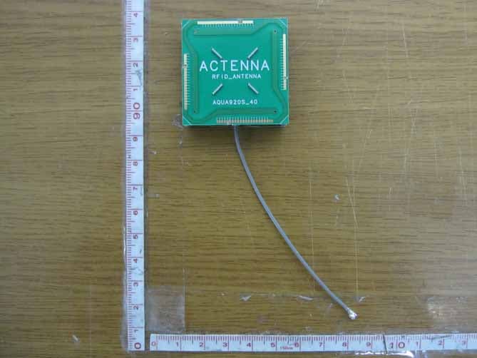
Y3DPRM90U21C
Jan 02, 2012UHF RFID READER HYBRID MODULE
Equipment Class
DSS - Part 15 Spread Spectrum Transmitter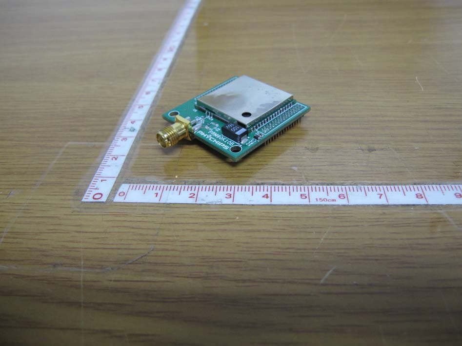
Y3DPRM90U10A
Dec 14, 2010UHF RFID READER HYBRID MODULE
Equipment Class
DSS - Part 15 Spread Spectrum Transmitter