Y3DPRM90U10AUHF RFID READER HYBRID MODULE
Phychips Inc.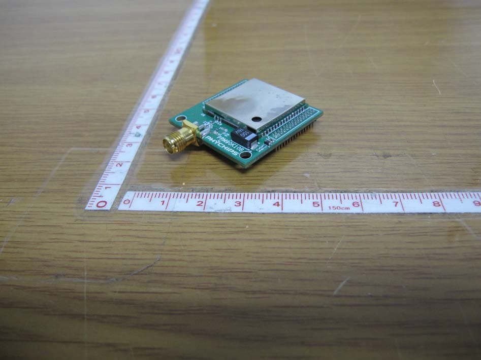
Click to zoom
Application Details
- Equipment Class
- DSS - Part 15 Spread Spectrum Transmitter
- Date of Grant
- Dec 14, 2010
- Application Purpose
- Original Equipment
- Date of Application
- Dec 13, 2010
- Equipment Note
- UHF RFID READER HYBRID MODULE
- Frequency Range
- 902.75000000 - 927.25000000
- Company
- Phychips Inc.
- Country
- South Korea
Documents & Files
Document Text
Text extracted from the exhibit documents filed with the FCC. Open a document above to read the original.
Users Manual
USER’S MANUAL December 2010 9 December 2010 2 of 13 PRM90U10A Specification- Preliminary Version Contents 1 Overview & block composition diagram ................................................... 3 2 Pin Description ............................................................................................ 4 3 Operation method........................................................................................ 6 4 Specification ................................................................................12 9 December 2010 3 of 13 PRM90U10A Specification- Preliminary Version 1 Overview & Block Composition Diagram 1.1 Overview The PRM90U10A is a UHF RFID Reader hybrid module which integrates high performance UHF RFID reader chipset, VC-TCXO, Low Drop Regulator, Balun, Coupler, Saw filter, Power amp, Isolator and low pass filter. UHF RFID reader chipset uses PR9000 of PHYCHIPS which integrates 900MHz radio, baseband processor, industry standard enhanced 8052 MCU, memory (64k Flash & 16k SRAM) and many other features. This module fully compliant with ISO18000-6C/EPC Global Gen II reader protocol and provide all functions of PR9000. Also reduce size, cost and power consumption. 1.2 Block Domposition Diagram PR9000 LDO BALUN DC 3.6V/500mA GPIO SHDNb RF I/O BALUNSAW AMP LPF COUPLER PRM90K10x 19.2MHz TCXO Figure 1 Block Composition Diagram 9 December 2010 4 of 13 PRM90U10A Specification- Preliminary Version 2 Pin Description 7 8 1 2 3 4 5 6 9 10 11 12 13 14 15 16 17 18 19 20 21 22 23 24 25 26 27 28 29 30 7 8 1 2 3 4 5 6 9 10 11 12 13 14 15 16 17 18 19 20 21 22 23 24 25 26 27 28 29 30 12345678910111213141516 35 34 33 32 31 30 29 28 27 26 25 24 23 22 21 20 17 18 19 Figure 2 Pin Description 2.1 J1 Pin Description No. Pin Name Description 1 VDD_3.6V 3.6 V DC Power for SOC(Max. 1A) 2 VDD_3.6V 3.6 V DC Power for SOC(Max. 1A) 3 VDD_3.6V 3.6 V DC Power for SOC(Max. 1A) 4 VDD_3.6V 3.6 V DC Power for SOC(Max. 1A) 5 GND Ground 6 GND Ground 7 GND Ground 8 GND Ground 9 NC Reserved, Not Ground 10 NC Reserved, Not Ground 11 NC Reserved, Not Ground 12 NC Reserved, Not Ground 13 GND Ground 14 GND Ground 15 NC Reserved, Not Ground 16 NC Reserved, Not Ground 17 GND Ground 18 GND Ground 9 December 2010 5 of 13 PRM90U10A Specification- Preliminary Version 19 P2.2 Quasi-bidirectional I/O port 20 NC Reserved, Not Ground 21 MDS_SCL I/O for ISP. The pull-up resistor is always switched on. This port is quasi- bidirectional 22 MDS_SDA I/O for ISP. The pull-up resistor is always switched on. This port is quasi- bidirectional 23 GND Ground 24 RESETb External Reset for SOC 25 P0.1 Quasi-bidirectional I/O port or Serial Port 0 Output 26 P0.0 Quasi-bidirectional I/O port or Serial Port 0 Input 27 NC Reserved, Not Ground 28 P0.2 Quasi-bidirectional I/O port or External Interrupt Input 0 29 P0.5 Quasi-bidirectional I/O port or Timer 1 External Input or SPI Master Output Slave Input 30 P0.4 Quasi-bidirectional I/O port or Timer 0 External Input or SPI Master Input Slave Output 2.2 J2 Pin Description No. Pin Name Description 1 NC Reserved, Not Ground 2 NC Reserved, Not Ground 3 GND Ground 4 GND Ground 5 NC Reserved, Not Ground 6 NC Reserved, Not Ground 7 GND Ground 8 GND Ground 9 TXD1 Quasi-bidirectional I/O port or Serial Port 1 Output 10 RXD1 Quasi-bidirectional I/O port or Serial Port 1 Input 11 GND Ground 12 GND Ground 13 P1.7 Quasi-bidirectional I/O port or External Interrupt 5 (Negative Edge) 14 P1.6 Quasi-bidirectional I/O port or External Interrupt 4 (Positive Edge) 15 P1.5 Quasi-bidirectional I/O port or External Interrupt 3 (Negative Edge) 16 P1.4 Quasi-bidirectional I/O port or External Interrupt 2 (Positive Edge) 17 P1.3 Quasi-bidirectional I/O port or I2C SCL 18 P1.2 Quasi-bidirectional I/O port or I2C SDA 19 P1.1 Quasi-bidirectional I/O port or Timer/ Counter 2 Capture/Reload Trigger 20 P1.0 Quasi-bidirectional I/O port or External Input for Timer/Counter 2 21 P0.7 Quasi-bidirectional I/O port or SPI Slave Select Bar 22 P0.6 Quasi-bidirectional I/O port or SPI SCK 23 NC Reserved, Not Ground 24 NC Reserved, Not Ground 25 NC Reserved, Not Ground 26 NC Reserved, Not Ground 27 GND Ground 28 GND Ground 29 SHDNb Module Enable/Disable Enable : Open Disable : Ground 9 December 2010 6 of 13 PRM90U10A Specification- Preliminary Version 30 SHDNb Module Enable/Disable Enable : Open Disable : Ground 2.3 S1 Pin Description(RF I/O) 3 Operation method DC 3.6V /150mA DC 3.6V /350mA NC NC ANT 1nF 0.1uF10uF 1nF 0.1uF10uF100uF ISP RESET MDS_SDA MDS_SCK VDD GND OPEN : NORMAL CLOSE : SHUT DOWN UART TXD RXD PRM90U10A VDD_36 GND NC TXD1 RXD1 GND P1.7 P1.6 P1.5 P1.4 P1.3 P1.2 P1.1 P1.0 P0.7 P0.6 P0.5 GNDRFIOGND NC GND P0.4 VDDPA_36 VDDPA_36 GND GND SHDN P2.2 MDS_SCL MDS_SDA RESET P0.0 P0.1 P0.2 1 2 3 4 5 6 7 8 9 10 11 12 13 14 15 16 17 1819 20 21 22 23 24 25 26 27 28 29 30 31 32 33 34 35 Figure 3 Application Circuit 3.1 Power Supply PRM90U10A should be supplied by 2 kinds of 3.6 volts DC power; VDD_36(Pin 1) and VDDPA_36(Pin 20, 21). VDD_36 is for operating of PR9000 RFID reader chipset which current consumption is about 150mA. VDDPA_36 is for operating of power amp which current consumption is 350mA typically. Additionally, decoupling capacitors should be placed as close as possible these pins. The decoupling capacitors should be placed in the same layer as the module, to avoid any additional parasitic inductance caused by vias. 3.2 Hardware Mode Control PRM90U10A provides normal mode and shut down mode. The mode can control by SHDNb(Pin 24). Normal mode should be controlled by SHDN pin to open which can activate the module. Otherwise, If SHDNb pin contact to ground, supplied power of the module is shut down internally. In shut down mode, all GPIO ports and UART ports should not input any signal and positive voltage. 3.3 UART The serial interface assigned to two pins. RXD1(Pin 13) is for receiving command from host and TXD1(Pin 14) is for transmitting response to host. Pin connection is shown as below figure. 9 December 2010 7 of 13…
Text truncated - open the document above for the full version.
Attestation Statements
#205 Migun Technoworld 1, 533, Yongsan-dong, Yuseong- gu, Daejeon, Korea, 305-500 TEL No : +82-42-864-2402 FAX No : +82-42-864-2403 ATTESTATION STATEMENT In re : Phychips Inc. FCC ID: Y3DPRM90U10A Date : December 9, 2010 15.247(a)(1) The hopping sequence must be pseudorandom all Channels are used equally on average the receiver input bandwidth is approximately equal to the transmit ba ndwidth the receiver hops in sequence with the transmitted signal 15.247(g) The system is designed to comply with all of the regulations in Section 15.247 when the transmitter is presented with a continuous data (or information) 15.247(h) The system does not coordinate its channel selection/hopping sequence with oth er frequency hopping systems for the express purpose of avoiding the simultane ous occupancy of individual hopping frequencies by multiple transmitters. Sincerely, Laekyu Chang Manager
Cover Letter(s)
#205 Migun Technoworld 1, 533, Yongsan-dong, Yuseong-gu, Daejeon, Korea, 305-500 TEL No : +82-42-864-2402 FAX No : +82-42-864-2403 December 8, 2010 Timco Engineering, Inc. 849 NW State Road 45 P.O.Box 370 Newberry,m Florida 32669 LETTER OF AUTHORIZATION To whom it may concern: We, the undersigned, hereby authorize LTA Co., Ltd., to act on our behalf in all manners relating to application for equipment authorization for FCC ID: Y3DPRM90U10A including signing of all documents relating to these matters. Any and all acts carried out by LTA Co., Ltd., on our behalf shall have the same affect as acts of our own. This authorization is valid until further written notice from Phychips Inc. LTA Co.,LTD. (Contact Person) Contact name: LEE, Kyung-Taek Position: Manager Phone:(82)31-323-6008 E-mail: [email protected] Sincerely, Laekyu Chang Manager
Cover Letter(s)
#205 Migun Technoworld 1, 533, Yongsan-dong, Yuseong-gu, Daejeon, Korea, 305-500 TEL No : +82-42-864-2402 FAX No : +82-42-864-2403 December 8, 2010 Federal Communications Commission Equipment Authorization Branch 7435 Oakland Mills Road Columbia, MD 21046 In re : Phychips Inc. FCC ID: Y3DPRM90U10A Request for Confidentiality Pursuant to Sections 0.457 and 0.459 of the Commission’s Rules (CFR 47), and Section 552 (b) (4) of the Freedom of Information Act, Phychips Inc.hereby requests confidentiality and treatment of certain information accompanying this application. The materials contain trade secrets and proprietary information not customarily released to the public. The public disclosure of these matters might be harmful to the Applicant and provide unjustified benefits to its competitors. We are also hereby request Short-Term Confidentiality for 180 days after the grant as outlined in Public Notice DA 04-1705. This provision will give Phychips Inc. temporary confidentiality of commercially sensitive information prior to product release. The requested Confidential and Temporary Confidential exhibits are listed as follows: Exhibit Type File Name Schematics CONF APPENDIX Y3DPRM90U10A SCH DIA.pdf Parts list CONF APPENDIX Y3DPRM90U10A PL.pdf Block diagram CONF APPENDIX Y3DPRM90U10A BLK DIA.pdf CONFIDENTIAL Operational description CONF APPENDIX Y3DPRM90U10A OpDes.pdf External Photos SHORT-TERM CONF Y3DPRM90U10A EXT Photo.pdf Internal Photos SHORT-TERM CONF Y3DPRM90U10A INT Photo.pdf Test-Setup Photos SHORT-TERM CONF Y3DPRM90U10A Test Photo.pdf SHORT-TERM CONFIDENTIAL User’s Manual SHORT-TERM CONF Y3DPRM90U10A Manual.pdf The Applicant understands that pursuant to Rule 0.457, disclosure of this application and all accompanying documentations, where applicable, will not be made public before the date of the Grant for this application. Sincerely, Laekyu Chang Manager
Cover Letter(s)
#205 Migun Technoworld 1, 533, Yongsan-dong, Yuseong-gu, Daejeo n, Korea, 305-500 TEL No : + 82-42-864-2402 FAX No : + 82-42-864-2403 FCC ID: Y3DPRM90U10A Request for Single Modular Approval Transmitter Module Characteristics The module will be used to the manufactured product by Phychips Inc. No Requirements EUT 1 Have its own RF shielding Device is equipped with metal shielding to cover RF section. Refer to external photos. 2 Have buffered modulation/data inputs (if such inputs are provided) All inputs to the modules are buffered th ought logic or microprocessor inputs. 3 Have it own power supply regulation The part numbe r of the power regulator is (MIC5205-3.3Y(B)M5) 4 Meet the antenna requirements of Section 15.203 T he antenna connector is the reverse SMA connector. 5 Be tested in a stand-alone configuration, i.e., the antenna, AC or DC power and data input/output lines must be connected to the module but, the module must not be inside another case during testing Please reference exhibition Test Conf iguration Photo for the stand-alone test configuration 6 Be labeled with its own FCC ID number, and if the FCC ID is not visible when the module is installed inside another device, then the out side of the device into which the module is installed must also display a label referring to the enclosed module Label is to be placed in front of the EUT(PR M90U10A), and other label is to be placed in the User’s Guide. Refer to FCC ID label format. 7 The modular transmitter is manufactured so t hat the user cannot influence the operation of the transmitter that will operate outsi de of the scope of the regulations. The EUT is compliant whith all applicable FCC rules. Detail instructions for maintaining compliance are given in the Users Manual. 8 Address compliance with the Commission’s RF exposure limits in Sections 1.1310 and 2.1091. In addition, spread spectrum transmitters operating under Section 15.247 are required to address RF exposure compliance in accordance with Section 15.247(b)(4). Please refer exhibition RF Exposure for th e compliance of MPE RF exposure rule.
External Photos
FCC ID: Y3DPRM90U10A Copyright ○ c 2010, LTA Co., Ltd. Page 1 of 2 FCC ID: Y3DPRM90U10A Copyright ○ c 2010, LTA Co., Ltd. Page 2 of 2 ANT
ID Label/Location Info
FCC ID: Y3DPRM90U10A Copyright Ⓒ 2010, LTA Co., Ltd. SAMPLE LABEL & LOCATION FCC ID: Y3DPRM90U10A M/N: PRM90U10A Made in Korea
Internal Photos
FCC ID: Y3DPRM90U10A Copyright ○ c 2010, LTA Co., Ltd. Page 1 of 2 FCC ID: Y3DPRM90U10A Copyright ○ c 2010, LTA Co., Ltd. Page 2 of 2
RF Exposure Info
ATTACHMENT FCC ID: Y3DPRM90U10A ** MPE Calculations ** The EUT will only be used with a separation of 20 centimeters or greater between the antenna and the body of the user. The MPE calculation for this exposure is shown below. The peak radiated output power (EIRP) is calculated as follows: EIRP = P + G EIRP = 23.58 dBm + (2.5)dBi EIRP = 26.08dBm Where, P = Power input to the antenna (mW) G = Power gain of the antenna (dBi) Power density at the specific separation: S = PG/(4R 2 π) S = (228.03 * 1.78) / (4 * 20 2 * π) S = 0.0807 mW/cm 2 Where, S = Maximum power density (mW/cm 2 ) P = Power input to the antenna (mW) G = Numeric power gain of the antenna R = Distance to the center of the radiation of the antenna (20cm = limit for MPE) The Maximum permissible exposure (MPE) for the general population is 1 mW/cm 2 . The power density at 20cm does not exceed the 1 mW/cm 2 limit. Therefore, the exposure condition is compliant with FCC rules. Estimated safe separation: R = √(PG / 4π) R = √(228.03 * 1.78/ 4π) R = 5.68Cm Where, P = Power input to the antenna (mW) G = Numeric power gain of the antenna R = Distance to the center of the radiation of the antenna (20cm = limit for MPE) The numeric gain(G) of the antenna with a gain specified in dB is determined by: G = Log -1 (dB antenna gain / 10) G = Log-1 ((2.5) / 10) G = 1.78
Test Report
Ref. No.: LR500111012G Copyright ○ c 2010, LTA Co., Ltd. Page 1 of 28 243 Jubug-Ri,Yangji-Myeon, Yongin-Si, Gyeonggi-Do, Korea 449-822 Tel: +82-31-323-6008 Fax: +82-31-323-6010 http://www.ltalab.com CERTIFICATION OF COMPLIANCE FCC ID. APPLICANT FCC Classification : FHSS Sequence Spread Spectrum (FHSS) Manufacturing Description : UHF RFID Reader hybrid module Manufacturer : Phychips Inc. Model name : PRM90U10A Test Device Serial No.: : Identification Rule Part(s) : FCC Part 15.247 Subpart C; ANSI C-63.4-2003 Frequency Range : 902.75 ~ 927.25MHz RF power : 0.23W - Conducted Data of issue : December 9, 2010 This test report is issued under the authority of: The test was supervised by: Kyung-Taek LEE, Technical Manager Hyun-Chae You, Test Engineer This test result only responds to the tested sample. It is not allowed to copy this report even partly without the allowance of the test laboratory. This report must not be used by the applicant to claim product endorsement by any agency. NVLAP LAB Code.: 200723-0 Dates of Tests: December 1~9, 2010 Test Report S/N: LR500111012G Test Site : LTA CO., LTD. Y3DPRM90U10A Phychips Inc. Ref. No.: LR500111012G Copyright ○ c 2010, LTA Co., Ltd. Page 2 of 28 TABLE OF CONTENTS 1. GENERAL INFORMATION’S -------------------------------------------------------------------------- 2. INFORMATION’S ABOUT TEST ITEM ------------------------------------------------------------- 3. TEST REPORT --------------------------------------------------------------------------------------------- 3.1 SUMMARY OF TESTS ------------------------------------------------------------------------------ 3.2 TECHNICAL CHARACTERISTICS TEST ------------------------------------------------------- 3.2.1 CARRIER FREQUENCY SEPARATION ---------------------------------------------------- 3.2.2 NUMBER OF HOPPING FREQUENCIES -------------------------------------------------- 3.2.3 20 dB BANDWIDTH ---------------------------------------------------------------------------- 3.2.4 TIME OF OCCUPANCY (Dwell Time) ------------------------------------------------------- 3.2.5 TANSMITTER OUTPUT POWER ---------------------------------------------------------- 3.2.6 BAND – EDGE (Conducted) ------------------------------------------------------------------- 3.2.7 FIELD STRENGTH OF HARMONICS ------------------------------------------------------ 3.2.8 AC CONDUCTED EMISSIONS -------------------------------------------------------------- APPENDIX APPENDIX TEST EQUIPMENT USED FOR TESTS ------------------------------------------- 3 4 5 5 6 6 8 10 13 15 18 23 26 27 Ref. No.: LR500111012G Copyright ○ c 2010, LTA Co., Ltd. Page 3 of 28 1. General information’s 1-1 Test Performed Company name : LTA Co., Ltd. Address : 243, Jubug-ri,Yangji-Myeon,Youngin-Si, Kyunggi-Do, Korea. 449-822 Web site : http://www.ltalab.com E-mail : [email protected] Telephone : +82-31-323-6008 Facsimile +82-31-323-6010 Quality control in the testing laboratory is implemented as per ISO/IEC 17025 which is the “General requirements for the competents of calibration and testing laboratory”. 1-2 Accredited agencies LTA Co., Ltd. is approved to perform EMC testing by the following agencies: Agency Country Accreditation No. Validity Reference NVLAP U.S.A 200723-0 2011-09-30 ECT accredited Lab. RRL KOREA KR0049 2011-06-20 EMC accredited Lab. FCC U.S.A 610755 2011-04-22 FCC filing VCCI JAPAN R2133, C2307 2011-06-21 VCCI registration IC CANADA IC5799 2012-05-14 IC filing Ref. No.: LR500111012G Copyright ○ c 2010, LTA Co., Ltd. Page 4 of 28 2. Information’s about test item 2-1 Applicant & Manufacturer Company name : Phychips Inc. Address : #205 Migun Technoworld 1, 533, Yongsan-dong, Yuseong-gu, Daejeon, Korea, 305-500 Tel / Fax : +82-42-864-2402/ +82-42-864-2403 2-2 Equipment Under Test (EUT) Trade name : UHF RFID Reader hybrid module FCC ID : Y3DPRM90U10A Model name : PRM90U10A Serial number : Identification Date of receipt : December 1, 2010 EUT condition : Pre-production, not damaged Antenna type : Quadrifilar Spiral Antenna Max Gain 2.5dBi Frequency Range : 902.75 ~ 927.25MHz RF output power : 0.23 W- Conducted Number of channels : 50 Channel spacing : 500KHz Channel Access Protocol : Frequency Hopping Power Source : 3.6VDC 2-3 Tested frequency LOW MID HIGH Frequency (MHz) 902.75 914.75 927.25 2-4 Ancillary Equipment Equipment Model No. Serial No. Manufacturer Notebook SENS P28 N/A Samsung PRINTER STYLUS C65 N/A EPSON Ref. No.: LR500111012G Copyright ○ c 2010, LTA Co., Ltd. Page 5 of 28 3. Test Report 3.1 Summary of tests FCC Part Section(s) Parameter Limit Test Condition Status (note 1) 15.247(a) Carrier Frequency Separation > 25 kHz C 15.247(a) Number of Hopping Frequencies ≥ 50 hops C 15.247(a) 20 dB Bandwidth - C 15.247 Dwell Time < 0.4 seconds C 15.247(b) Transmitter Output Power < 1Watt C 15.247(d) Conducted Spurious emission > 20 dBc C 15.247(d) Band Edge > 20 dBc Conducted C 15.249 / 15.209 Field Strength of Harmonics Emission Radiated C 15.207 AC Conducted Emissions Emissions Conducted NA note3 Note 1: C=Complies NC=Not Complies NT=Not Tested NA=Not Applicable Note 2: The data in this test report are traceable to the national or international standards. Note 3: This device is only operated by DC The sample was tested according to the following specification: FCC Parts 15.247; ANSI C-63.4-2003 Antenna Requirement The Phychips Inc. PRM90U10A unit complies with the requirement of §15.203. The Antenna type is Reversed Type ; Refer to the External photo Ref. No.: LR500111012G Copyright ○ c 2010, LTA Co., Ltd. Page 6 of 28 3.2 Transmitter requirements 3.2.1 Carrier Frequency Separation Procedure: The carrier frequency separation was measured with a spectrum analyzer connected to the antenna terminal, while EUT had its hopping function enabled. After the trace being stable, the reading value between the peaks of the adjacent channels using the marker-delta function was recorded as the measurement results. The spectrum analyzer is set to: Span = 1…
Text truncated - open the document above for the full version.
Test Setup Photos
FCC ID: Y3DPRM90U10A Copyright Ⓒ 2010, LTA Co., Ltd. Radiated Emission
Contact Information
Applicant
Khyungjoo Min(Principal Research Engineer)
Test Firm
LTA Co.,Ltd.Michael AHN
Technical Specifications
| # | Rule Parts | Frequency Range | Power Output |
|---|---|---|---|
| 1 | 15C | 902.75 MHz - 927.25 MHz | 230.00 mW |
Other Applications from Phychips Inc.
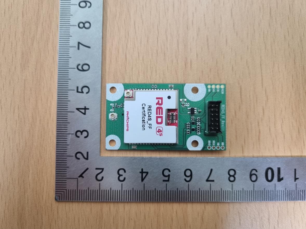
Y3D-RED4SFF
Jul 18, 2023RFID Module
Equipment Class
DSS - Part 15 Spread Spectrum TransmitterY3DA100U
Aug 19, 2013SMART RFID DONGLE READER
Equipment Class
DSS - Part 15 Spread Spectrum Transmitter
Y3DPRM92K20CE
Jan 13, 2013UHF RFID MODULE
Equipment Class
DSS - Part 15 Spread Spectrum Transmitter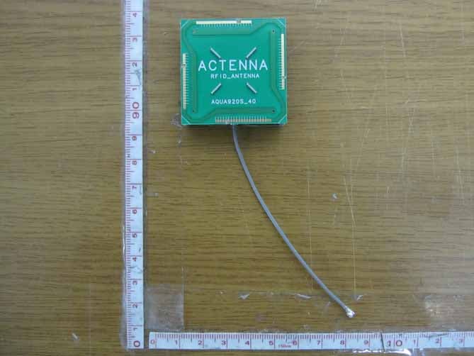
Y3DPRM90U21C
Jan 02, 2012UHF RFID READER HYBRID MODULE
Equipment Class
DSS - Part 15 Spread Spectrum Transmitter