Y478818C24Universal Small Cell 8818 LTE/LTE Module
SpiderCloud Wireless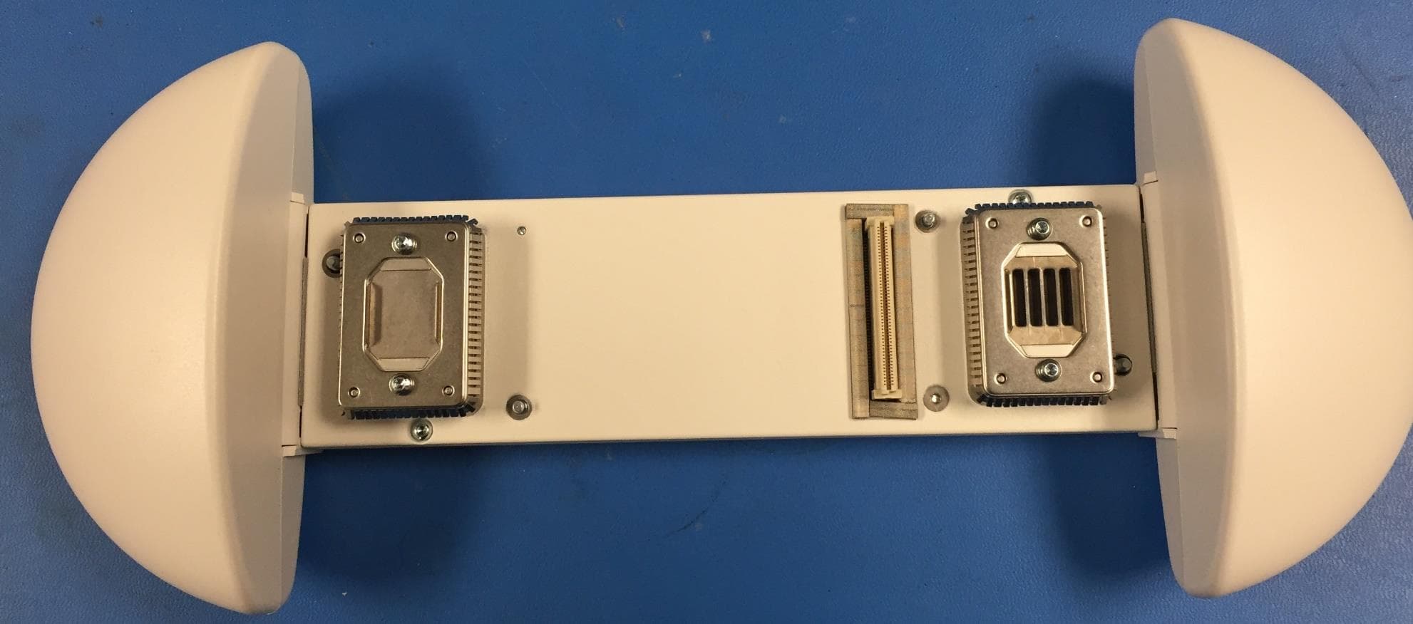
Click to zoom
Application Details
- Equipment Class
- PCB - PCS Licensed Transmitter
- Date of Grant
- Nov 23, 2015
- Application Purpose
- Original Equipment
- Date of Application
- Nov 23, 2015
- Equipment Note
- Universal Small Cell 8818 LTE/LTE Module
- Frequency Range
- 2120.00000000 - 2145.00000000
- Company
- SpiderCloud Wireless
- Country
- United States
Documents & Files
Document Text
Text extracted from the exhibit documents filed with the FCC. Open a document above to read the original.
Users Manual
Cisco USC 8718/8818 Installation Guide Cisco USC 8718/8818Dual-ModeSmall Cell ModuleInstallation2 BeforeYou Begin2 InstallYour SmallCell Module5 AntennaPatterns13 SafetyInstructions19 Revised: October 26, 2015, Cisco USC 8718/8818 Dual-Mode Small Cell Module Installation Before You Begin The CiscoUniversalSmallCell (USC)8718 dual-modesmallcell moduleprovideseither3G or 4G cellularcoveragein an indoor environmentwhereimprovedcoverageand capacityis desiredfor cellularservices.The USC 8818 smallcell moduleprovidesLTE cellularcoverageon a software-selectableLTE band.The smallcell modulesare specificallydesignedto workwith CiscoAironet 3600/3700seriesWi-Fi accesspoints(APs)or the USC 5030 smallcell chassis.Each smallcell moduleis capableof supporting eitherUniversalMobileTelecommunicationsSystem(UMTS),whereapplicable,or LongTerm Evolution(LTE) radioprotocolsin a singleplatform,is 3GPPcompliantand supportsUMTSRelease7 and LTE Release9 standards. Each USC 8718 modulecan supporteither: • up to 32 simultaneousUMTSvoiceand data channels,a peak downlinkrate of 21 Mbpsand a peak uplinkrate of 5 Mbps • up to 32 activeLTE usersper radio,a peak downloadrate of 100 Mbps,and a peak uploadof 50 Mbpswhenused with 20 MHz channelbandwidth The USC 8818 is a dual-band,LTE-only, software-switchablemodulethat can supportup to 32 simultaneousLTE channelson either LTE cell, a peak downloadrate of 100 Mbps,and uplinkof 50 Mbpswhenused with 20 MHzchannelbandwidth. 2 Thesesmallcell modulesenablemobileoperatorsto offer dedicated,in-buildingcoverageand capacityfor UMTSand LTE services. Theyare managedby the CiscoUSC 8088 controllerinstalledin the enterprise. Figure 1: Small Cell Relationship to Enterprise and Mobile Operator Core Networks System Requirements The varioussmallcell modulesare designedfor use with the followinghardware: Table 1: Small Cell Modules and Supported Hardware Supported HardwareMonitor BandsTransmit BandsSmall Cell Module Aironet3700 AP Rev 2 USC 5030 UMTSBands1, 8 LTE Bands3, 7, 20 GSM925-960MHzand 1805-1880MHz UMTSBand1 LTE Band7 USC8718-M17-K9 3 Supported HardwareMonitor BandsTransmit BandsSmall Cell Module Aironet3600 AP Aironet3700 AP USC 5030 UMTSBands2, 5 LTE Bands2, 4 GSM869-894MHz UMTSBand2 LTE Band4 USC 8718-M24-K9 Aironet3600 AP Aironet3700 AP USC 5030 UMTSBands1, 8 LTE Bands3, 7, 20 GSM925-960MHzand 1805-1880MHz UMTSBand1 LTE Band3 USC8718-M13-K9 Aironet3600 AP Aironet3700 AP USC 5030 UMTSBands1, 5, 8 LTE Bands1, 3, 7 GSM925-960MHzand 1805-1880MHz LTE Band1 LTE Band3 USC8818-C13-K9 USC 8000 seriesmodulesare compatiblewith the CiscoAironet–i variantswith internalantennaswhen they are ceilingmounted(for example,Cisco3700i).Theyare not compatiblewith CiscoAironet–e variantswhenhorizontalmountedor with externalantennas(for example,Cisco3700e). Note The smallcell modulesare not designedfor use with otheraccesspoints.The smallcell modulesare managedby the CiscoUSC 8088 controllerinstalledin the enterprise.The controllerhas two variants,one for high capacityand anotherfor low capacity. These two variantsdiffer in relationto the accessmodulesinstalledin the hardware. Software Requirements The smallcell modulesare supportedon Release4.1.5 and above. The smallcell modulesare compatiblewith softwarerelease8.1 MR or beyondof the wirelessLANcontroller. Pleaseverifythat the properreleaseversionis availableon the wirelessLANcontrollerat the time of installation. Power Considerations Installationof your smallcell modulecan requirean additional10 wattsto powerthe CiscoAironetaccesspoint.With a smallcell moduleinstalled,the accesspointrequiresthe full Powerover EthernetPlus (PoE+)of 25.5 Watts at the egressswitchport and a cablerun of less than 300 feet (100 meters). Poweroptionsfor the accesspointinclude: • IEEE802.3atPOE+25.5 W deliveredfrom the upstreamEthernetswitch • Cisco3600 SeriesPowerInjector(AIR-PWRINJ4=) • Cisco3600 Serieslocal powersupply(AIR-PWR-B=) The smallcell modulehas a powerlimit circuitrythat shutsdownthe moduleif it drawsmorepowerthan allowed. 4 Installation Considerations Installyour smallcell: • in a centrallocation,in an area wherepeopleare most likelyto makecalls • awayfrom windows,to avoidthe signalleakingoutsideor externalsignalsleakingin • in an open area with airflow;not in a closedcabinetwhichreducesthe signalstrength • at least 5 meters(16 feet) from an externalwall. This distancemaximizesindoorcoverageand minimizesRF leakageoutside the building.Referto the CiscoUSC 8000 SeriesDeploymentPlanningGuidefor Dual-ModeSystemsand CiscoUSC 8000 SeriesDeploymentPlanningGuidefor LTE Systemsfor moreinformationaboutsmallcell placement. If you have thick internalwalls,or metal,fire or rotatingdoors,plan to placeunits at eitherside of the obstructionat a distanceshorter than 49 feet (15 m). Installa unit acrossfrom a cornerto providecoverageon both sides of the corner. For moreinformation,refer to the "CiscoAironetAP Modulefor WirelessSecurityand SpectrumIntellgence(WSSI)Deployment Guide"at the followingURL:http://www.cisco.com/en/US/products/ps11983/products_tech_note09186a0080bed15d.shtml. Install Your Small Cell Module The smallcell modulecan be installedin eithera CiscoAironet3600 seriesaccesspoint(AP),a CiscoAironet3700 seriesAP or the CiscoUSC 5030 chassisaccordingto theseinstructions: 5 Procedure Step 1 Removethe modulefrom the packaging. Step 2 Powerdownthe accesspointif you are installingthe smallcell moduleinto an operationalaccesspoint. Step 3 Peel off the label from the back of the AP to revealthe moduleport connector. Figure 2: Backside of Cisco Aironet 3600 Access Point Openingsfor module'santennas1 Labelcoveringport connector2 6 Step 4 Alignthe moduleconnectorwith the connectoron the back of the AP or USC 5030 chassissuch that the male and female 100-pinmezzanineconnectorsmate. Figure 3: Installing Module in the Cisco 5030 Chassis 10/100Base-TEthernetport4Smallcell module1 Powerport for DC powersource5Openingsfor moduleantennas2 Port connector3 Step 5 Hold both units in …
Text truncated - open the document above for the full version.
Cover Letter(s)
SCS-F18: Project and Product Certification Representative Authorization Letter Page 1 of 2 Rev 5.0 775 Montague Expressway Milpitas, CA 95035 Tel: 408-526-1188 Fax: 408-526-1088 Email: [email protected] Project and Product Certification Representative Authorization Letter Reason for Amendment (current / obsolete) Revision History Approved Date From To Initial Release (obsolete) 1.0 1.0 Nov-14-2006 Revised wording (obsolete) 1.0 2.0 Sept–25-2007 Updated company template (obsolete) 2.0 3.0 Jan-31-2012 Updated letter information (obsolete) 3.0 4.0 May-23-2014 Added FCC ID field (current) 4.0 5.0 Sept 16 2014 SCS-F18: Project and Product Certification Representative Authorization Letter Page 2 of 2 Rev 5.0 11/20/2015 To: SIEMIC, Inc. 775 Montague Expressway, Milpitas, CA 95035 USA Dear Sir/Madam, Re: Project and Product Certification Representative Authorization Letter We, SpiderCloud Wireless, hereby authorize SIEMIC, Inc. to act as Certification Body for certifying for the following project(s): FCC ID: Y478818C24 Product description: Universal Small Cell 8818 LTE/LTE Module Model number: USC8818-C24-K9 We affirm that between SIEMIC, Inc. and SpiderCloud Wireless, any difference in understanding, including test plan, measurement methods, applicable standards and relevant procedures and processes have been resolved prior to commencement of testing activities. Sincerely, Tassos Michail / Director Product Management SpiderCloud Wireless 408 E. Plumeria Drive, San Jose 95134 [email protected] / 408-235-2910
Cover Letter(s)
SCS-F19: Confidentiality Request Letter Page 1 of 3 Rev 4.0 775 Montague Expressway Milpitas, CA 95035 Tel: 408-526-1188 Fax: 408-526-1088 Email: [email protected] Confidentiality Request Letter Reason for Amendment (current / obsolete) Revision History Approved Date From To Initial Release (obsolete) 1.0 1.0 Nov-14-2006 Adding CFR 2.459 (obsolete) 1.0 2.0 August – 11 - 2008 Updated company template & Added text box (obsolete) 2.0 3.0 Jan-31-2012 Added IC confidentiality letter form (current) 3.0 4.0 March-26-2015 SCS-F19: Confidentiality Request Letter Page 2 of 3 Rev 4.0 11/20/2015 To: Federal Communications Commission Authorization and Evaluation Division 7435 Oakland Mills Road Columbia, MD Subject: Permanent Confidentiality Request for FCC ID: Y478818C24 We hereby request confidential treatment of information accompanying this application as outlined below: - Block Diagram - Schematics - Operational Description - Tune up Procedure - Part List The above materials contain trade secrets and proprietary information not customarily released to the public. The public disclosure of these materials may be harmful to the applicant and provide unjustified benefits to its competitors. The applicant understands that pursuant to Section 0.457 & 0.459 of the Rules, disclosure of this application and all accompanying documentation will not be made before the date of the Grant for this application. Sincerely, Tassos Michail / Director Product Management SpiderCloud Wireless 408 E. Plumeria Drive, San Jose 95134 [email protected] / 408-235-2910 SCS-F19: Confidentiality Request Letter Page 3 of 3 Rev 4.0 11/20/2015 To: Federal Communications Commission Office of Engineering and Technology Equipment Authorization Division 7345 Oakland Mills Road Columbia, Maryland 21046 Subject: Short Term Confidentiality Request for FCC ID: Y478818C24 To Whom It May Concern: Pursuant to sections 0.457 and 0.459 of CFR 47 and to avoid premature release of sensitive information prior to marketing or release of the product to the public, the applicant requests the following documents contained in this certification application be temporarily withheld from public disclosure for an initial period of 45 or 180 days (please check one). - User Manual - Internal Photos The above materials contain trade secrets and proprietary information not customarily released to the public. The public disclosure of these materials may be harmful to the applicant and provide unjustified benefits to its competitors. Sincerely, Tassos Michail / Director Product Management SpiderCloud Wireless 408 E. Plumeria Drive, San Jose 95134 [email protected] / 408-235-2910
External Photos
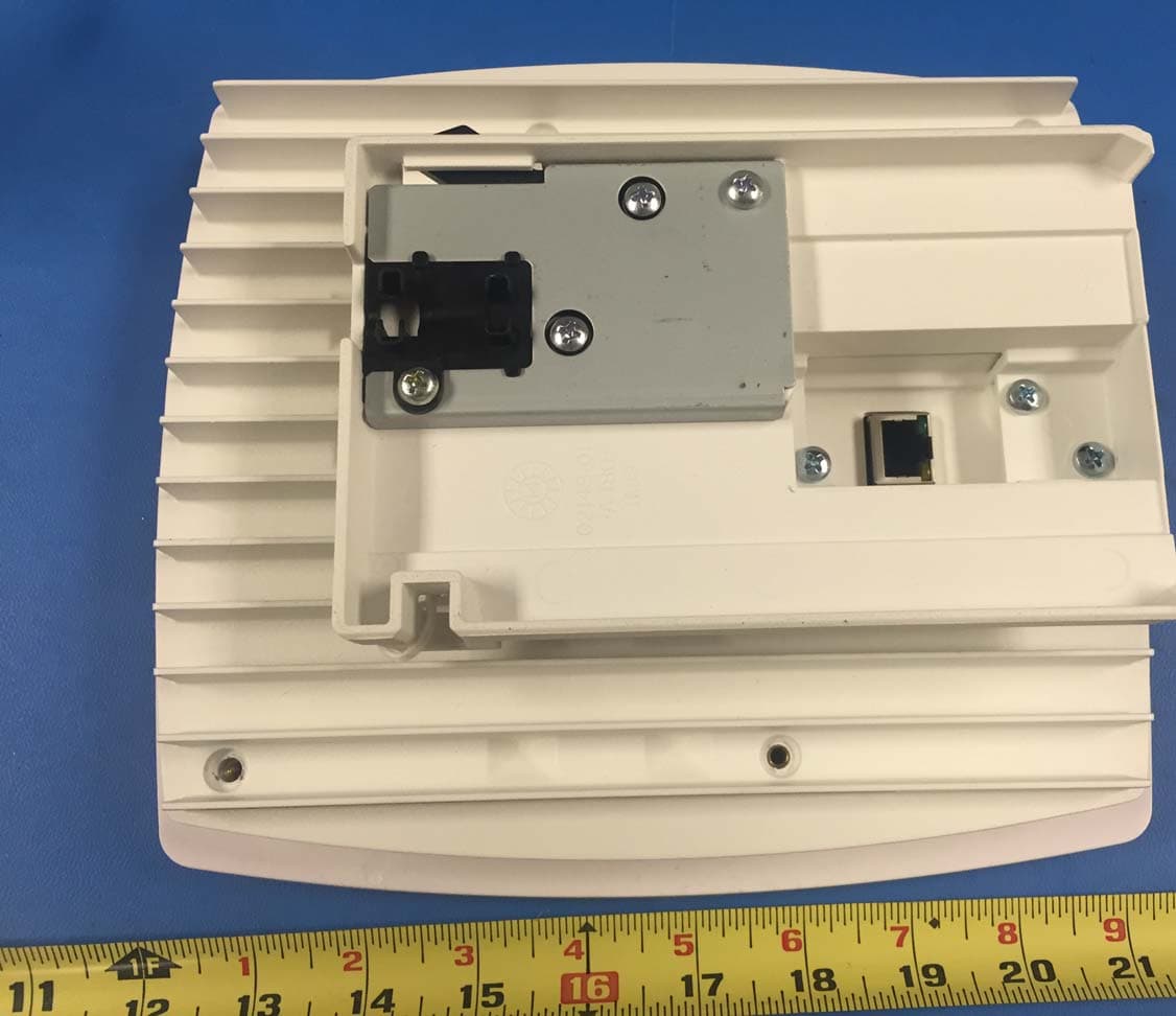
External Photos Front Back
Internal Photos
Internal Photos Connector Side Up Side Up Side Without Shield
RF Exposure Info
775 Montague Expressway, Milpitas, CA 95035, USA • Phone: (+1) 408 526 1188 • Facsimile (+1) 408 526 1088 Visit us at: www.siemic.com; Follow us at: Issued By: SIEMIC Laboratories 775 Montague Expressway, Milpitas, 95035 CA RF Exposure Report Report No.: FCC_MPE_SL15090401-SPC-046_0402 Supersede Report No.: None This Test Report is Issued Under the Authority of: Chen Ge Nima Molaei Test Engineer Reviewer Engineer This test report may be reproduced in full only Test result presented in this test report is applicable to the tested sample only Applicant : SpiderCloud Wireless, Inc. Product Name : Universal Small Cell USC8818 Band 2/4 LTE/LTE Module Model No. : USC8818-C24-K9 RF Exposure Requirements : 47 CFR §1.1307(b) RF Exposure Limits : 47 CFR §1.1310 RF Radiation Exposure Guidelines : FCC OST/OET Bulletin Number 65 Issue Date : 11/17/2015 Test Result : ☒ Pass ☐ Fail Equipment complied with the specification [ X ] Equipment did not comply with the specification [ ] Test report No. FCC_MPE_SL15090401-SPC-046_0402 Page 2 of 9 775 Montague Expressway, Milpitas, CA 95035, USA • Phone: (+1) 408 526 1188 • Facsimile (+1) 408 526 1088 Visit us at: www.siemic.com; Follow us at: Laboratory Introduction SIEMIC, headquartered in the heart of Silicon Valley, with superior facilities in US and Asia, is one of the leading independent testing and certification facilities providing customers with one-stop shop services for Compliance Testing and Global Certifications. In addition to testing and certification, SIEMIC provides initial design reviews and compliance management throughout a project. Our extensive experience with China, Asia Pacific, North America, European, and International compliance requirements, assures the fastest, most cost effective way to attain regulatory compliance for the global markets. Accreditations for Conformity Assessment Country/Region Accreditation Body Scope USA FCC, A2LA EMC, RF/Wireless, Telecom Canada IC, A2LA, NIST EMC, RF/Wireless, Telecom Taiwan BSMI, NCC, NIST EMC, RF, Telecom, Safety Hong Kong OFTA, NIST RF/Wireless, Telecom Australia NATA, NIST EMC, RF, Telecom, Safety Korea KCC/RRA, NIST EMI, EMS, RF, Telecom, Safety Japan VCCI, JATE, TELEC, RFT EMI, RF/Wireless, Telecom Mexico NOM, COFETEL, Caniety Safety, EMC, RF/Wireless, Telecom Europe A2LA, NIST EMC, RF, Telecom, Safety Israel MOC, NIST EMC, RF, Telecom, Safety Accreditations for Product Certifications Country Accreditation Body Scope USA FCC TCB, NIST EMC, RF, Telecom Canada IC FCB, NIST EMC, RF, Telecom Singapore iDA, NIST EMC, RF, Telecom EU NB EMC & R&TTE Directive Japan MIC (RCB 208) RF, Telecom Hong Kong OFTA (US002) RF, Telecom Test report No. FCC_MPE_SL15090401-SPC-046_0402 Page 3 of 9 775 Montague Expressway, Milpitas, CA 95035, USA • Phone: (+1) 408 526 1188 • Facsimile (+1) 408 526 1088 Visit us at: www.siemic.com; Follow us at: CONTENTS 1 REPORT REVISION HISTORY ....................................................................................................................................... 4 2 EXECUTIVE SUMMARY ................................................................................................................................................. 5 3 CUSTOMER INFORMATION .......................................................................................................................................... 5 4 TEST SITE INFORMATION ............................................................................................................................................ 5 5 MODIFICATION ............................................................................................................................................................. 5 6 EUT INFORMATION ...................................................................................................................................................... 6 6.1 EUT Description ........................................................................................................................................................ 6 7 FCC RF EXPOSURE EVALUATION ................................................................................................................................ 7 7.1 Limits ....................................................................................................................................................................... 7 7.2 MPE Calculation Formula ........................................................................................................................................... 7 7.3 MPE Calculations ...................................................................................................................................................... 7 7.4 MPE Calculation Results ............................................................................................................................................ 7 ANNEX A. SIEMIC ACCREDITATION ..................................................................................................................................... 8 Test report No. FCC_MPE_SL15090401-SPC-046_0402 Page 4 of 9 775 Montague Expressway, Milpitas, CA 95035, USA • Phone: (+1) 408 526 1188 • Facsimile (+1) 408 526 1088 Visit us at: www.siemic.com; Follow us at: 1 Report Revision History Report No. Report Version Description Issue Date FCC_MPE_SL15090401-SPC-046_0402 None Original 11/17/2015 Test report No. FCC_MPE_SL15090401-SPC-046_0402 Page 5 of 9 775 Montague Expressway, Milpitas, CA 95035, USA • Phone: (+1) 408 526 1188 • Facsimile (+1) 408 526 1088 Visit us at: www.siemic.com; Follow us at: 2 Executive Summary The purpose of this test program was to demonstrate compliance of following product Company: SpiderCloud Wireless, Inc. Product: Universal Small Cell USC8818 Band 2/4 LTE/LTE Model: USC8818-C24-K9 against the current Stipulated Standards. The specified model product stated above has demonstrated compliance with the Stipulated Standard listed…
Text truncated - open the document above for the full version.
Test Report
775 Montague Expressway, Milpitas, CA 95035, USA • Phone: (+1) 408 526 1188 • Facsimile (+1) 408 526 1088 Visit us at: www.siemic.com; Follow us at: Report No.: FCC_RF_SL15090401-SPC-046_0402 Rev 1.0 Supersede Report No.: FCC_RF_SL15090401-SPC-046_0402 Applicant SpiderCloud Wireless, Inc. Product Name Universal Small Cell USC8818 Band 2/4 LTE/LTE Module Model No. USC8818-C24-K9 Test Standard 47CFR Part 24/27 Test Method TIA-603-D: 2010 FCC ID Y478818C24 Date of test 04/13/2015 - 05/03/2015 10/26/2015 - 11/02/2015 Issue Date 03/10/2017 Test Result Pass Fail Equipment complied with the specification [ x ] Equipment did not comply with the specification [ ] Chen Ge Nima Molaei Test Engineer Engineer Reviewer This test report may be reproduced in full only Test result presented in this test report is applicable to the tested sample only Issued By: SIEMIC Laboratories 775 Montague Expressway, Milpitas, 95035 CA RF TEST REPORT Test report No. FCC_RF_SL15090401-SPC-046_0402 Rev 1.0 Page 2 of 76 775 Montague Expressway, Milpitas, CA 95035, USA • Phone: (+1) 408 526 1188 • Facsimile (+1) 408 526 1088 Visit us at: www.siemic.com; Follow us at: Laboratory Introduction SIEMIC, headquartered in the heart of Silicon Valley, with superior facilities in US and Asia, is one of the leading independent testing and certification facilities providing customers with one-stop shop services for Compliance Testing and Global Certifications. In addition to testing and certification, SIEMIC provides initial design reviews and compliance management throughout a project. Our extensive experience with China, Asia Pacific, North America, European, and International compliance requirements, assures the fastest, most cost effective way to attain regulatory compliance for the global markets. Accreditations for Conformity Assessment Country/Region Accreditation Body Scope USA FCC, A2LA EMC , RF/Wireless , Telecom Canada IC, A2LA, NIST EMC, RF/Wireless , Telecom Taiwan BSMI , NCC , NIST EMC, RF, Telecom , Safety Hong Kong OFTA , NIST RF/Wireless ,Telecom Australia NATA, NIST EMC, RF, Telecom , Safety Korea KCC/RRA, NIST EMI, EMS, RF , Telecom, Safety Japan VCCI, JATE, TELEC, RFT EMI, RF/Wireless, Telecom Mexico NOM, COFETEL, Caniety Safety, EMC , RF/Wireless, Telecom Europe A2LA, NIST EMC, RF, Telecom , Safety Israel MOC, NIST EMC, RF, Telecom, Safety Accreditations for Product Certifications Country Accreditation Body Scope USA FCC TCB, NIST EMC , RF , Telecom Canada IC FCB , NIST EMC , RF , Telecom Singapore iDA, NIST EMC , RF , Telecom EU NB EMC & R&TTE Directive Japan MIC (RCB 208) RF , Telecom HongKong OFTA (US002) RF , Telecom Test report No. FCC_RF_SL15090401-SPC-046_0402 Rev 1.0 Page 3 of 76 775 Montague Expressway, Milpitas, CA 95035, USA • Phone: (+1) 408 526 1188 • Facsimile (+1) 408 526 1088 Visit us at: www.siemic.com; Follow us at: CONTENTS 1 REPORT REVISION HISTORY ....................................................................................................................................... 4 2 EXECUTIVE SUMMARY ................................................................................................................................................. 5 3 CUSTOMER INFORMATION .......................................................................................................................................... 5 4 TEST SITE INFORMATION ............................................................................................................................................ 5 5 MODIFICATION ............................................................................................................................................................. 5 6 EUT INFORMATION ...................................................................................................................................................... 6 6.1 EUT Description ........................................................................................................................................................ 6 6.2 Radio Description ...................................................................................................................................................... 7 6.3 EUT test modes/configuration Description.................................................................................................................... 8 6.4 EUT Photos - External ............................................................................................................................................... 9 6.5 EUT Photos - Internal .............................................................................................................................................. 10 6.6 EUT Test Setup Photos ........................................................................................................................................... 11 7 SUPPORTING EQUIPMENT/SOFTWARE AND CABLING DESCRIPTION ....................................................................... 12 7.1 Supporting Equipment ............................................................................................................................................. 12 7.2 Test Software Description ........................................................................................................................................ 12 8 TEST SUMMARY ......................................................................................................................................................... 13 9 MEASUREMENT UNCERTAINTY ................................................................................................................................. 14 10 MEASUREMENTS, EXAMINATION AND DERIVED RESULTS .................................................................................. 15 10.1 RF Output Power ........................................................................................................................................…
Text truncated - open the document above for the full version.
Test Report
Test report No. FCC_RF_SL15090401-SPC-046_0402 Rev 1.0 Page 52 of 76 775 Montague Expressway, Milpitas, CA 95035, USA • Phone: (+1) 408 526 1188 • Facsimile (+1) 408 526 1088 Visit us at: www.siemic.com; Follow us at: Test Plots for LTE Band2 QPSK OBW- Band2-10M BW-Low OBW- Band2-20M BW-Low OBW- Band2-10M BW-Mid OBW- Band2-20M BW-Mid OBW- Band2-10M BW-High OBW- Band2-20M BW-High Test report No. FCC_RF_SL15090401-SPC-046_0402 Rev 1.0 Page 53 of 76 775 Montague Expressway, Milpitas, CA 95035, USA • Phone: (+1) 408 526 1188 • Facsimile (+1) 408 526 1088 Visit us at: www.siemic.com; Follow us at: Test Plots for LTE Band2 QPSK OBW- Band2-5M BW-Low OBW- Band2-15M BW-Low OBW- Band2-5M BW-Mid OBW- Band2-15M BW-Mid OBW- Band2-5M BW-High OBW- Band2-15M BW-High Test report No. FCC_RF_SL15090401-SPC-046_0402 Rev 1.0 Page 54 of 76 775 Montague Expressway, Milpitas, CA 95035, USA • Phone: (+1) 408 526 1188 • Facsimile (+1) 408 526 1088 Visit us at: www.siemic.com; Follow us at: Test Plots for LTE Band2 64QAM OBW- Band2 -10M BW-Low OBW- Band2 -20M BW-Low OBW- Band2 -10M BW-Mid OBW- Band2-20M BW-Mid OBW- Band2 -10M BW-High OBW- Band2-20M BW-High Test report No. FCC_RF_SL15090401-SPC-046_0402 Rev 1.0 Page 55 of 76 775 Montague Expressway, Milpitas, CA 95035, USA • Phone: (+1) 408 526 1188 • Facsimile (+1) 408 526 1088 Visit us at: www.siemic.com; Follow us at: Test Plots for LTE Band2 64QAM OBW- Band2-5M BW-Low OBW- Band2-15M BW-Low OBW- Band2-5M BW-Mid OBW- Band2-15M BW-Mid OBW- Band2-5M BW-High OBW-Band2-15M BW-High Test report No. FCC_RF_SL15090401-SPC-046_0402 Rev 1.0 Page 56 of 76 775 Montague Expressway, Milpitas, CA 95035, USA • Phone: (+1) 408 526 1188 • Facsimile (+1) 408 526 1088 Visit us at: www.siemic.com; Follow us at: 10.4 Band Edge Requirement(s): Spec Item Requirement Applicable 47CFR27.53 - Out of band emissions. The power of any emission outside of the authorized operating frequency ranges must be attenuated below the transmitting power (P) by a factor of at least 43 + 10 log(P) dB. ☒ 47CFR24.238 - Out of band emissions. The power of any emission outside of the authorized operating frequency ranges must be attenuated below the transmitting power (P) by a factor of at least 43 + 10 log(P) dB. ☒ Test Setup Test Procedure 1. EUT was set for low , mid, high channel with modulated mode and highest RF output power. 2. The spectrum analyzer was connected to the antenna terminal. 3. A RBW of 1% greater than the 26 dB emission bandwidth should be used for band edge measurement or if narrower RBW is used, a correct factor calculated with formula 10*log (EBW/BWmeas) will be added to the result. Test Date 04/30/2015 - 05/03/2015 10/26/2015 – 11/02/2015 Environmental condition Temperature 22 o C Relative Humidity 48% Atmospheric Pressure 1008mbar Remark The EUT was scanned up to 25GHz. Both horizontal and vertical polarities were investigated. The results show only the worst case. Limit calculation: Emission limit = PdBm – [ 43+ 10 log (PW)] = 10log(1000 x PW) - 43 - 10log(PW) = 30 dBm - 43 = -13 dBm 100KHz RBW was used to make measurement for LTE Band 4 with 20MHz BW, so the correction factor will be added to correct the result to be using 200 KHz RBW. Result ☒ Pass ☐ Fail Test Data ☒ Yes ☐ N/A Test Plot ☒ Yes (See below) ☐ N/A Test report No. FCC_RF_SL15090401-SPC-046_0402 Rev 1.0 Page 57 of 76 775 Montague Expressway, Milpitas, CA 95035, USA • Phone: (+1) 408 526 1188 • Facsimile (+1) 408 526 1088 Visit us at: www.siemic.com; Follow us at: Band Edge Measurement Data for LTE band 4 Type Channel Channel Frequency (MHz) Measurement Band Edge (dBm) RBW Correction factor (dB) Corrected Band Edge (dBm) Limit (dBm) 5MHz BW, QPSK Low 2115 -23.19 0 -23.19 -13 High 2150 -26.13 0 -26.13 -13 5MHz BW, 16QAM Low 2115 -38.97 0 -38.97 -13 High 2150 -34.55 0 -34.55 -13 5MHz BW, 64QAM Low 2115 -26.10 0 -26.10 -13 High 2150 -29.02 0 -29.02 -13 10MHz BW, QPSK Low 2120 -32.03 0 -32.03 -13 High 2145 -32.66 0 -32.66 -13 10MHz BW, 16QAM Low 2120 -42.35 0 -42.35 -13 High 2145 -42.59 0 -42.59 -13 10MHz BW, 64QAM Low 2120 -34.03 0 -34.03 -13 High 2145 -35.73 0 -35.73 -13 15MHz BW, QPSK Low 2115 -36.39 3.01 -33.38 -13 High 2150 -37.51 3.01 -34.50 -13 15MHz BW, 16QAM Low 2115 -41.83 3.01 -38.82 -13 High 2150 -40.24 3.01 -37.23 -13 15MHz BW, 64QAM Low 2115 -38.90 3.01 -35.89 -13 High 2150 -37.41 3.01 -34.40 -13 20MHz BW, QPSK Low 2120 -37.83 3.01 -34.82 -13 High 2145 -39.44 3.01 -36.43 -13 20MHz BW, 16QAM Low 2120 -45.58 3.01 -42.57 -13 High 2145 -43.42 3.01 -40.41 -13 20MHz BW, 64QAM Low 2120 -40.24 3.01 -37.23 -13 High 2145 -40.52 3.01 -37.51 -13 Band Edge Measurement Data for LTE band 2 Type Channel Channel Frequency (MHz) Measurement Band Edge (dBm) Limit (dBm) 5MHz BW, QPSK Low 1932.5 -38.28 -13 High 1987.5 -51.94 -13 5MHz BW, 64QAM Low 1932.5 -38.28 -13 High 1987.5 -52.28 -13 10MHz BW, QPSK Low 1935 -38.26 -13 High 1985 -48.27 -13 10MHz BW, 64QAM Low 1935 -37.53 -13 High 1985 -47.39 -13 15MHz BW, QPSK Low 1937.5 -39.98 -13 High 1982.5 -47.55 -13 15MHz BW, 64QAM Low 1937.5 -36.06 -13 High 1982.5 -47.72 -13 20MHz BW, QPSK Low 1940 -46.08 -13 High 1980 -48.38 -13 20MHz BW, 64QAM Low 1940 -45.63 -13 High 1980 -47.90 -13 Test report No. FCC_RF_SL15090401-SPC-046_0402 Rev 1.0 Page 58 of 76 775 Montague Expressway, Milpitas, CA 95035, USA • Phone: (+1) 408 526 1188 • Facsimile (+1) 408 526 1088 Visit us at: www.siemic.com; Follow us at: Test Plots BandEdge-LTE-Band4-5MHz-QPSK-Low BandEdge-LTE-Band4-5MHz-QPSK-High BandEdge-LTE-Band4-5MHz-16QAM-Low BandEdge-LTE-Band4-5MHz-16QAM-High BandEdge-LTE-Band4-5MHz-64QAM-Low BandEdge-LTE-Band4-5MHz-64QAM-High Test report No. FCC_RF_SL15090401-SPC-046_0402 Rev 1.0 Page 59 of 76 775 Montague Expressway, Milpitas, CA 95035, USA • Phone: (+1) 408 526 1188 • Facsimile (+1) 408 526 1088 Visit us at: www.siemic.com; Follow us at: BandEdge-LTE-Band4-10MHz-QPSK-Low BandEdge-LTE-Band4-10MHz-QPSK-High BandEdge-LTE-Band4-10MHz-16QAM-Low BandEdge-LTE-Band4-10MHz-16QAM-High BandEdge-LTE-Band4-10MHz-64…
Text truncated - open the document above for the full version.
Test Report
Test report No. FCC_RF_SL15090401-SPC-046_0402 Rev 1.0 Page 72 of 76 775 Montague Expressway, Milpitas, CA 95035, USA • Phone: (+1) 408 526 1188 • Facsimile (+1) 408 526 1088 Visit us at: www.siemic.com; Follow us at: 10.7 Frequency Stability Requirement(s): Spec Item Requirement Applicable 47 CFR 2.1055, 47 CFR - The frequency stability of the transmitter shall be maintained within ±0.0001 percent (±1 ppm) of the center frequency over a temperature variation of −30 °Celsius to +50 °Celsius at normal supply voltage, and over a variation in the primary supply voltage of 85 percent to 115 percent of the rated supply voltage at a temperature of 20 °Celsius. ☒ 47 CFR 2.1055, 47 CFR 24.135(a), - The frequency stability of the transmitter shall be maintained within ±0.0001 percent (±1 ppm) of the center frequency over a temperature variation of −30 °Celsius to +50 °Celsius at normal supply voltage, and over a variation in the primary supply voltage of 85 percent to 115 percent of the rated supply voltage at a temperature of 20 °Celsius. ☒ 47 CFR 2.1055, 47 CFR 27.54 - The frequency stability shall be sufficient to ensure that the fundamental emissions stay within the authorized bands of operation. ☒ Test Setup Test Procedure The carrier frequency of the transmitter is measured at room temperature (20°C to provide a reference). 1. The equipment is turned on in a “standby” condition for one minute before applying power to the transmitter. Measurement of the carrier frequency of the transmitter is made within one minute after applying power to the transmitter. 2. Frequency measurements are made at 10°C intervals ranging from -30°C to +50°C. A period of at least one half hour is provided to allow stabiliza…
Text truncated - open the document above for the full version.
Contact Information
Applicant
Timothy Lam(Sr. QA Manager)
Test Firm
SIEMIC LabsLeslie BAI
[email protected]4085261188
Technical Specifications
| # | Rule Parts | Frequency Range | Power Output | Emission | Tolerance |
|---|---|---|---|---|---|
| 8 | 27 | 2.12 GHz - 2.15 GHz | 120.00 mW | 17M8W7D | 0.009 ppm |
Other Applications from SpiderCloud Wireless
Y47RN310B4B2E
Oct 08, 2015SpiderCloud Radio Node
Equipment Class
PCB - PCS Licensed Transmitter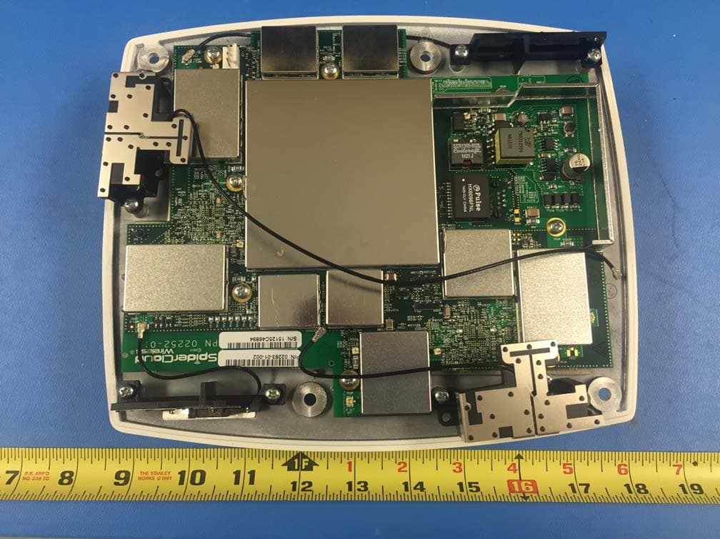
Y47RN310B4B13E
Oct 08, 2015SpiderCloud Radio Node
Equipment Class
TNB - Licensed Non-Broadcast Station Transmitter
Y478718M24
May 14, 2015Universal Small Cell 8718
Equipment Class
PCB - PCS Licensed TransmitterY47RN310B7B2
Dec 21, 2014SpiderCloud Radio Node
Equipment Class
PCB - PCS Licensed Transmitter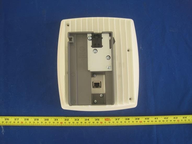
Y47RN310B4B13
Mar 30, 2014SpiderCloud Radio Node
Equipment Class
TNB - Licensed Non-Broadcast Station Transmitter