Y47RN310B4B13ESpiderCloud Radio Node
SpiderCloud Wireless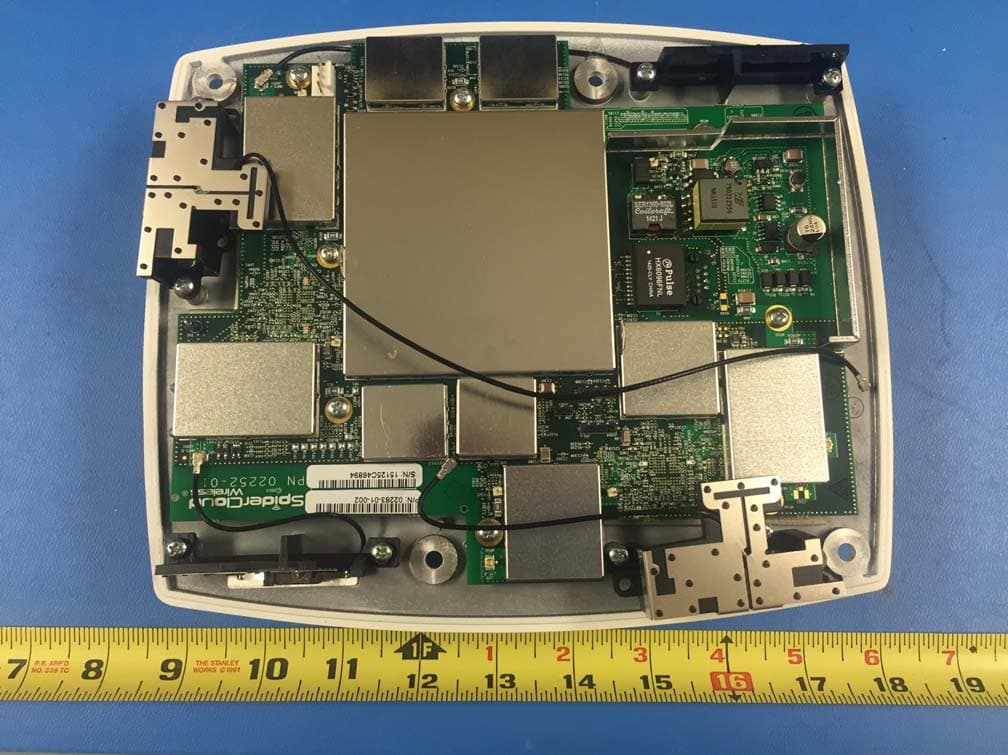
Click to zoom
Application Details
- Equipment Class
- TNB - Licensed Non-Broadcast Station Transmitter
- Date of Grant
- Oct 08, 2015
- Application Purpose
- Original Equipment
- Date of Application
- Sep 22, 2015
- Equipment Note
- SpiderCloud Radio Node
- Frequency Range
- 2120.00000000 - 2145.00000000
- Company
- SpiderCloud Wireless
- Country
- United States
Documents & Files
Document Text
Text extracted from the exhibit documents filed with the FCC. Open a document above to read the original.
Users Manual
SpiderCloud ® Radio Node - SCRN-310 Hardware Installation Guide Part number: DOC-SCRN-310-HW-01, Rev. 0.1 DRAFT Published: February 2014 ® 2 FCC Statements Caution: Any changes or modification cautions to this device not explicitly approved by manufacturer could void your authority to operate this equipment. This equipment complies with FCC radiation exposure limits set forth for an uncontrolled environment. This equipment should be installed and operated with minimum 20 cm between the radiator and your body. This transmitter must not be collocated or operating in conjunction with any other antenna or transmitter unless authorized to do so by the FCC. Legal Notice Customer agrees that the Software, including the specific design and structure of individual programs, and the Documentation are protected by United States and foreign copyright and trade secret laws. Customer agrees not to reproduce, disclose, alter, provide or otherwise make available such trade secrets or copyrighted material in any form to any third party without the prior written consent of SpiderCloud Wireless. Customer agrees to implement reasonable security measures to protect such trade secrets and copyrighted material at least to the extent that Customer protects its own information of a similar nature. The information contained herein is subject to change without notice. Although all information is believed to be accurate at the date of publication, SpiderCloud assumes no responsibility for inaccuracies contained herein. Copyright © 2014 SpiderCloud Wireless, Inc. SpiderCloud Wireless is a registered trademark and SmartCloud a trademark of SpiderCloud Wireless, Inc. All rights reserved. SpiderCloud Wireless 408 East Plumeria Drive San Jose, CA 95134, USA http://www.spidercloud.com Tel: +1 408 567-9165 Email: [email protected] Revision History RevisionDateSummary of Changes 0.12/19/2014Initial draft document release SpiderCloud Wireless, Inc. SpiderCloud Radio Node - SCRN-310 Hardware Installation Guide 3 Table of Contents About this Manual . . . . . . . . . . . . . . . . . . . . . . . . . . . . . . . . . . . . . . . . . . . . . . . . . . . . . . . . . . . 5 System Overview . . . . . . . . . . . . . . . . . . . . . . . . . . . . . . . . . . . . . . . . . . . . . . . . . . . . . . . . . . . . 5 Radio Node Features . . . . . . . . . . . . . . . . . . . . . . . . . . . . . . . . . . . . . . . . . . . . . . . . . . . . . . 6 Radio Node System Isometric Top View and Bottom View. . . . . . . . . . . . . . . . . . . . . . . . . . 6 System Specifications . . . . . . . . . . . . . . . . . . . . . . . . . . . . . . . . . . . . . . . . . . . . . . . . . . . . . . . . 7 Frequency Bands of Operation . . . . . . . . . . . . . . . . . . . . . . . . . . . . . . . . . . . . . . . . . . . . . . . 7 Size and Dimensions. . . . . . . . . . . . . . . . . . . . . . . . . . . . . . . . . . . . . . . . . . . . . . . . . . . . . . . 7 Environmental Requirements . . . . . . . . . . . . . . . . . . . . . . . . . . . . . . . . . . . . . . . . . . . . . . . . 7 Power . . . . . . . . . . . . . . . . . . . . . . . . . . . . . . . . . . . . . . . . . . . . . . . . . . . . . . . . . . . . . . . . . . 8 Compliance . . . . . . . . . . . . . . . . . . . . . . . . . . . . . . . . . . . . . . . . . . . . . . . . . . . . . . . . . . . . . . 8 Radio Node Models . . . . . . . . . . . . . . . . . . . . . . . . . . . . . . . . . . . . . . . . . . . . . . . . . . . . . . . . . . 8 Antennas. . . . . . . . . . . . . . . . . . . . . . . . . . . . . . . . . . . . . . . . . . . . . . . . . . . . . . . . . . . . . . . . . . . 9 Ports . . . . . . . . . . . . . . . . . . . . . . . . . . . . . . . . . . . . . . . . . . . . . . . . . . . . . . . . . . . . . . . . . . . . . . 9 The Top-Panel LED . . . . . . . . . . . . . . . . . . . . . . . . . . . . . . . . . . . . . . . . . . . . . . . . . . . . . . . . . . 9 Input Power . . . . . . . . . . . . . . . . . . . . . . . . . . . . . . . . . . . . . . . . . . . . . . . . . . . . . . . . . . . . . . . . 10 Select the Radio Node Location . . . . . . . . . . . . . . . . . . . . . . . . . . . . . . . . . . . . . . . . . . . . . . . . 11 Installation and Mount Bracket Assembly. . . . . . . . . . . . . . . . . . . . . . . . . . . . . . . . . . . . . . . . 12 Bracket Mounting and Cabling Guidelines . . . . . . . . . . . . . . . . . . . . . . . . . . . . . . . . . . . . . . 13 Typical Radio Node Mounting Options . . . . . . . . . . . . . . . . . . . . . . . . . . . . . . . . . . . . . . . . . 13 Installing the Radio Node . . . . . . . . . . . . . . . . . . . . . . . . . . . . . . . . . . . . . . . . . . . . . . . . . . . 13 Installing the Radio Node (Method 1) . . . . . . . . . . . . . . . . . . . . . . . . . . . . . . . . . . . . . . . . . . 13 Installing the Radio Node (Method 2) . . . . . . . . . . . . . . . . . . . . . . . . . . . . . . . . . . . . . . . . . . 15 Completing the Installation . . . . . . . . . . . . . . . . . . . . . . . . . . . . . . . . . . . . . . . . . . . . . . . . . . 17 Detaching the Radio Node from the Mount Bracket . . . . . . . . . . . . . . . . . . . . . . . . . . . . . . . 17 Boot Sequence and Services Node Communication . . . . . . . . . . . . . . . . . . . . . . . . . . . . . . . 18 Radio Node LED Boot Sequence . . . . . . . . . . . . . . . . . . . . . . . . . . . . . . . . . . . . . . . . . . . . . . . 19 Radio Node LED Management . . . . . . . . . . . . . . . . . . . . . . . . . . . . . . . . . . . . . . . . . . . . . . . . . 20 The SpiderCloud Documentation Set . . . . . . . . . . . . . . . . . . . . . . . . . . . . . . . . . . . . . . . . . . . 22 Appendix AUMTS Antenna Patterns . . . . . . . . . . . . . . . . . . . . . . . . . . . . . . . . . . . . . . . . . 23 Appendix BLTE Antenna Patterns . . . . . . . . . . . . . . . . . . . . . . . . . . . . . . . . . . . . . . . . . . 27 SpiderCloud Wireless, Inc. Contents 4 SpiderCloud Wireless, Inc. 5 SpiderCloud Radio Node - SCRN-310 Hardware Installat…
Text truncated - open the document above for the full version.
Users Manual
SpiderCloud Radio Node - SCRN-310 Hardware Installation Guide SpiderCloud Wireless, Inc. 15 Figure 12 Fully Mounted Installing the Radio Node (Method 2) To route the cable directly and mount the radio node Step 1 Route the Ethernet cable through the large hole in the mounting bracket. Figure 13 Mount Bracket with Direct Cable Routing Step 2 With two user-provided screws, attach the mount bracket assembly to a wall or ceiling. The screw holes are sized for an M4 (#10) screw. Ensure the screws have a snug fit onto the studs, sheetrock, anchor, or other material you are bolting onto. Step 3 Insert the RJ-45 connector into the Ethernet port as shown in Figure 14: Transmit Side SpiderCloud Radio Node - SCRN-310 Hardware Installation Guide SpiderCloud Wireless, Inc. 16 Figure 14 Route and Terminate the Cable Step 4 Push as much cable back through the wall or ceiling as possible. The mount bracket assembly has room for some cable slack. Step 5 Slide the pedestal base of the radio node into the groove opening in the mount bracket. When the pedestal reaches the end of the trough, a spring clip will secure the unit into place. Figure 15 Fully Mounted RJ-45 Connector in Ethernet Port SpiderCloud Radio Node - SCRN-310 Hardware Installation Guide SpiderCloud Wireless, Inc. 17 Completing the Installation Step 1 Attach a padlock or cable tie wrap through the cutout lock holes in the mount bracket and pedestal base. Figure 16 Padlock and Lock Holes The lock in the above figure is shown schematically. The orientation is for illustration purposes (not accurate) since the bracket is typically wall or ceiling mounted. Step 2 The radio node boots up and attempts to connect to the services node. Refer to Boot Sequence and Services Node Communication on page 18 for more information. Detaching the Radio Node from the Mount Bracket To remove the radio node from the bracket assembly Step 1 If needed, remove the padlock or cable tie wrap securing the radio node. Step 2 Depress the spring clip on the pedestal base and slide the radio node out of the mount bracket. Step 3 Detach the RJ-45 clip from the Ethernet port and remove the cable from cable brackets and cable opening. SpiderCloud Radio Node - SCRN-310 Hardware Installation Guide SpiderCloud Wireless, Inc. 18 Boot Sequence and Services Node Communication On initial boot, the radio node performs the following boot sequence and communicates with the services node. It performs this boot sequence twice, first for the UMTS subsystem, then again for the LTE subsystem. This sequence takes about one minute to complete for each subsystem. When finished, all devices are reachable. Figure 17 shows the radio node boot sequence: Figure 17 Radio Node Boot Sequence UMTS Sequence Description: 1. When the radio node is powered on, the device sends a DHCP Request to the services node DHCP server to get IP information. The DHCP server is configured on the services node to respond only to DHCP requests from SpiderCloud Wireless radio nodes. Refer to the SpiderCloud OS (SCOS) Administrator Guide for more information about the services node DHCP server configuration. 2. The server responds with the IP addresses of the radio node and the services node (the master of the radio node). 3. Using its own IP address, the radio node sends a Join Request message to the services node. The radio node seeks to join the cellular network. 4. The services node responds with a Join Response message indicating whether the radio node is allowed to join the network or not. 5. The arrival sequence begins. Based on the configuration of the radio node, the radio node will join the system and get its configuration. The services node sends the SpiderCloud software image (the system image and configuration settings) to the radio node. 6. The radio node reboots and mounts the SpiderCloud software image as a RAM-based file system. 7. The radio node contacts the services node and joins the network. USBCONSOLE LKAT LKAT LKAT LKAT LKAT LKAT LKAT LKAT 81234567 LNKACT MGMT POWERSTATUS12 SIM 0SIM 1 Radio NodeServices Node DHCP Request for IP Address DHCP Response (RN, IP, Controller IP) Join Request Join Response (Join Grant, Redirect, Denied) Arrival sequence begins Send SpiderCloud software package Mount package, join the network SpiderCloud Radio Node - SCRN-310 Hardware Installation Guide SpiderCloud Wireless, Inc. 19 Radio Node LED Boot Sequence The radio node state machine is sequential and progresses in the following order: State 0 -> State 1 -> State 2 -> State 3 -> State 4 -> State 5 A normal boot sequence transitions through all these states sequentially and the LED state transitions accordingly. If the radio node fails to transition to the next state, the system restarts the boot sequence, starting with State 0. You can determine the progress during the booting stages by observing the LED color transitions. On failure, the last LED state will display the state that encountered the failure. Ta b l e 3 shows the radio node boot sequence and corresponding LED behavior: Table 3: Radio Node LED Boot Sequence StateLED ColorDescriptionPossible Failures and Actions 0. Power On/ Reset Flashing Green This is the initial state on startup. The radio node bootup is controlled by firmware in this state. It will go through a lamp test in this state. A lamp test involves cycling through all LED colors. This state should be very short lived and should transition to the next state immediately. A radio node should not stay in this state indefinitely. Note: Flashing Green is also used to indicate a radio node that has been administratively disabled. This can be determined from the CLI. 1. DHCPSolid Red The radio node starts by sending out a DHCP Request. The radio node moves to the next state (State 2) upon receiving a DHCP response and an IP Address. No DHCP Response, IP Address not allocated. Check cabling, DHCP Server configuration. 2. JoinSolid Blue The radio node has an IP Address and sends a UDP Join request to the S…
Text truncated - open the document above for the full version.
Cover Letter(s)
SCS-F18: Project and Product Certification Representative Authorization Letter Page 1 of 2 Rev 5.0 775 Montague Expressway Milpitas, CA 95035 Tel: 408-526-1188 Fax: 408-526-1088 Email: [email protected] Project and Product Certification Representative Authorization Letter Reason for Amendment (current / obsolete) Revision History Approved Date From To Initial Release (obsolete) 1.0 1.0 Nov-14-2006 Revised wording (obsolete) 1.0 2.0 Sept–25-2007 Updated company template (obsolete) 2.0 3.0 Jan-31-2012 Updated letter information (obsolete) 3.0 4.0 May-23-2014 Added FCC ID field (current) 4.0 5.0 Sept 16 2014 SCS-F18: Project and Product Certification Representative Authorization Letter Page 2 of 2 Rev 5.0 09/25/2015 To: SIEMIC, Inc. 775 Montague Expressway, Milpitas, CA 95035 USA Dear Sir/Madam, Re: Project and Product Certification Representative Authorization Letter We, SpiderCloud Wireless, hereby authorize SIEMIC, Inc. to act as Certification Body for certifying for the following project(s): FCC ID: Y47RN310B4B2E Product description: SpiderCloud Radio Node Model name: SCRN-310-0413-E We affirm that between SIEMIC, Inc. and SpiderCloud Wireless, any difference in understanding, including test plan, measurement methods, applicable standards and relevant procedures and processes have been resolved prior to commencement of testing activities. Sincerely, Tassos Michail / Director Product Management SpiderCloud Wireless 408 E. Plumeria Drive, San Jose 95134 [email protected] / 408-235-2910
Cover Letter(s)
SCS-F19: Confidentiality Request Letter Page 1 of 3 Rev 4.0 775 Montague Expressway Milpitas, CA 95035 Tel: 408-526-1188 Fax: 408-526-1088 Email: [email protected] Confidentiality Request Letter Reason for Amendment (current / obsolete) Revision History Approved Date From To Initial Release (obsolete) 1.0 1.0 Nov-14-2006 Adding CFR 2.459 (obsolete) 1.0 2.0 August – 11 - 2008 Updated company template & Added text box (obsolete) 2.0 3.0 Jan-31-2012 Added IC confidentiality letter form (current) 3.0 4.0 March-26-2015 SCS-F19: Confidentiality Request Letter Page 2 of 3 Rev 4.0 09/25/2015 To: Federal Communications Commission Authorization and Evaluation Division 7435 Oakland Mills Road Columbia, MD Subject: Permanent Confidentiality Request for FCC ID: Y47RN310B4B13E We hereby request confidential treatment of information accompanying this application as outlined below: - Block Diagram - Schematics - Operational Description - Tune up Procedure - Part List The above materials contain trade secrets and proprietary information not customarily released to the public. The public disclosure of these materials may be harmful to the applicant and provide unjustified benefits to its competitors. The applicant understands that pursuant to Section 0.457 & 0.459 of the Rules, disclosure of this application and all accompanying documentation will not be made before the date of the Grant for this application. Sincerely, Tassos Michail / Director Product Management SpiderCloud Wireless 408 E. Plumeria Drive, San Jose 95134 [email protected] / 408-235-2910 SCS-F19: Confidentiality Request Letter Page 3 of 3 Rev 4.0 09/25/2015 To: Federal Communications Commission Office of Engineering and Technology Equipment Authorization Division 7345 Oakland Mills Road Columbia, Maryland 21046 Subject: Short Term Confidentiality Request for FCC ID: Y47RN310B4B13E To Whom It May Concern: Pursuant to sections 0.457 and 0.459 of CFR 47 and to avoid premature release of sensitive information prior to marketing or release of the product to the public, the applicant requests the following documents contained in this certification application be temporarily withheld from public disclosure for an initial period of 45 or 180 days (please check one). - User Manual - Internal Photos The above materials contain trade secrets and proprietary information not customarily released to the public. The public disclosure of these materials may be harmful to the applicant and provide unjustified benefits to its competitors. Sincerely, Tassos Michail / Director Product Management SpiderCloud Wireless 408 E. Plumeria Drive, San Jose 95134 [email protected] / 408-235-2910
ID Label/Location Info
1 234 567 D C B AA B C D 765 432 1 MODIFICATIONS REVISIONDESCRIPTIONDATE © 2015 SPIDERCLOUD WIRELESS C SIZEDRAWING BY TITLE SPIDERCLOUD ENGINEER DATE DRAWING NUMBER TOLERANCES REV PROPRIETARY AND CONFIDENTIAL THE INFORMATION CONTAINED IN THIS DRAWING IS THE SOLE PROPERTY OF SPIDERCLOUD WIRELESS. ANY REPRODUCTION IN PART OR WHOLE WITHOUT THE WRITTEN PERMISSION OF SPIDERCLOUD WIRELESS IS PROHIBITED. ALL RIGHTS RESERVED 02531-0101 09/8/15 SEE NOTES LABEL, AGENCY + RATINGS, SCRN-310-0413-E Sheet 1 of 1 01INITIAL RELEASE9/8/2015 408 East Plumeria Drive San Jose, CA 95134 NOTES: 1. ALL DIMENSIONS ARE IN INCHES. INTERPRET DIMENSIONS AND TOLERANCES PER ANSI Y14.5 1994. 2. TOLERANCES: DECIMALS .X = ± 0.05 .XX = ± 0.025 ANGLES = ± 0.5• 3. MATERIAL: .002” MATTE SILVER POLYESTER WITH .001” MATTE LAMINATION. 4. ADHESIVE: CLEAR, PERMANENT, ACRYLIC ADHESIVE. 5. COLOR: BACKGROUND: SILVER. GRAPHICS: PMS BLACK. 6. LABEL MATERIAL, ADHESIVE AND PRINTING PROCESS TO CONFORM TO UL STANDARDS FOR USE ON ABS PLASTIC AND METAL SURFACES. 7. VISUAL INSPECTION OF PART TO MEET CLASS A PER SPIDERCLOUD COSMETIC SPECIFICATION. 8. OUTLINES AND FEATURE LINES ARE FOR REFERENCE ONLY AND DO NOT PRINT. THIS FILE CONTAINS ARTWORK AND ART SPECIFICATIONS. Model: SCRN-310-0413-E Input Rating: 56V 0.6A ® CUS Model: SCRN-310-0413-E Input Rating: 56V 0.6A ® CUS 200% for reference only R 0.05 (4X) 5.45 .33 FCC ID: Y47RN310B4B13E FCC ID: Y47RN310B4B13E SpiderCloud WirelessStanley Mercado
Internal Photos
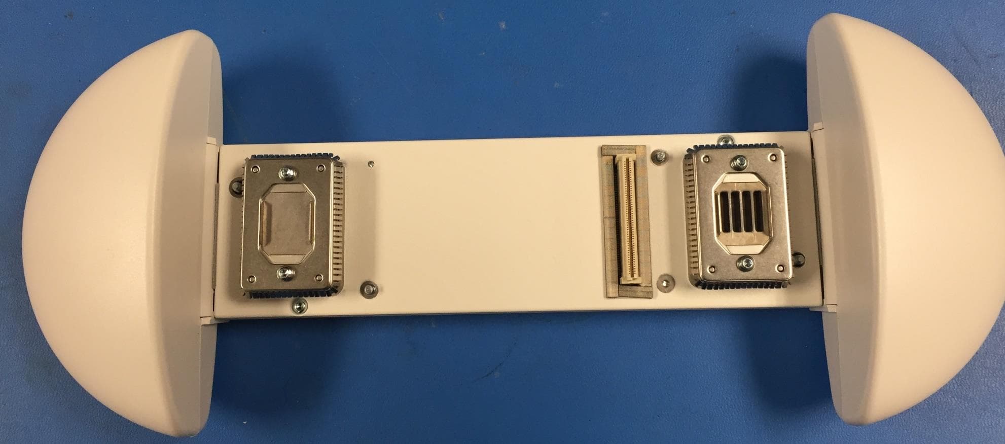
Pictures for SCRN‐310‐0413
RF Exposure Info
775 Montague Expressway, Milpitas, CA 95035, USA • Phone: (+1) 408 526 1188 • Facsimile (+1) 408 526 1088 Visit us at: www.siemic.com; Follow us at: Issued By: SIEMIC Laboratories 775 Montague Expressway, Milpitas, 95035 CA RF Exposure REPORT Report No.: FCC-IC_MPE_SL15083101-SPC-042_0413 Supersede Report No.: NONE This Test Report is Issued Under the Authority of: Nima Molaei Chen Ge Test Engineer Reviewer Engineer This test report may be reproduced in full only Test result presented in this test report is applicable to the tested sample only Applicant : SpiderCloud Wireless, Inc. Product Name : SpiderCloud Radio Node Model No. : SCRN-310-0413-E RF Exposure Requirements : 47 CFR §1.1307(b), RSS-102 Issue 5, March 2015 RF Exposure Limits : 47 CFR §1.1310, RSS-102 Issue 5, March 2015 RF Radiation Exposure Guidelines : FCC OST/OET Bulletin Number 65 RSS-102 Issue 5, March 2015 Issue Date : 05/04/2015 Test Result : ☒ Pass ☐ Fail Equipment complied with the specification [ X ] Equipment did not comply with the specification [ ] Test report No. FCC-MPE_SL15083101-SPC-042_0413 Page 2 of 11 775 Montague Expressway, Milpitas, CA 95035, USA • Phone: (+1) 408 526 1188 • Facsimile (+1) 408 526 1088 Visit us at: www.siemic.com; Follow us at: Laboratory Introduction SIEMIC, headquartered in the heart of Silicon Valley, with superior facilities in US and Asia, is one of the leading independent testing and certification facilities providing customers with one-stop shop services for Compliance Testing and Global Certifications. In addition to testing and certification, SIEMIC provides initial design reviews and compliance management throughout a project. Our extensive experience with China, Asia Pacific, North America, European, and International compliance requirements, assures the fastest, most cost effective way to attain regulatory compliance for the global markets. Accreditations for Conformity Assessment Country/Region Accreditation Body Scope USA FCC, A2LA EMC, RF/Wireless, Telecom Canada IC, A2LA, NIST EMC, RF/Wireless, Telecom Taiwan BSMI, NCC, NIST EMC, RF, Telecom, Safety Hong Kong OFTA, NIST RF/Wireless, Telecom Australia NATA, NIST EMC, RF, Telecom, Safety Korea KCC/RRA, NIST EMI, EMS, RF, Telecom, Safety Japan VCCI, JATE, TELEC, RFT EMI, RF/Wireless, Telecom Mexico NOM, COFETEL, Caniety Safety, EMC, RF/Wireless, Telecom Europe A2LA, NIST EMC, RF, Telecom, Safety Israel MOC, NIST EMC, RF, Telecom, Safety Accreditations for Product Certifications Country Accreditation Body Scope USA FCC TCB, NIST EMC, RF, Telecom Canada IC FCB, NIST EMC, RF, Telecom Singapore iDA, NIST EMC, RF, Telecom EU NB EMC & R&TTE Directive Japan MIC (RCB 208) RF, Telecom Hong Kong OFTA (US002) RF, Telecom Test report No. FCC-MPE_SL15083101-SPC-042_0413 Page 3 of 11 775 Montague Expressway, Milpitas, CA 95035, USA • Phone: (+1) 408 526 1188 • Facsimile (+1) 408 526 1088 Visit us at: www.siemic.com; Follow us at: CONTENTS 1 REPORT REVISION HISTORY ....................................................................................................................................... 4 2 EXECUTIVE SUMMARY ................................................................................................................................................. 5 3 CUSTOMER INFORMATION .......................................................................................................................................... 5 4 TEST SITE INFORMATION ............................................................................................................................................ 5 5 MODIFICATION ............................................................................................................................................................. 5 6 EUT INFORMATION ...................................................................................................................................................... 6 6.1 EUT Description ........................................................................................................................................................ 6 7 RF EXPOSURE ............................................................................................................................................................. 7 7.1 Limits ....................................................................................................................................................................... 7 7.2 MPE Calculation Formula ........................................................................................................................................... 7 7.3 MPE Calculations ...................................................................................................................................................... 7 7.4 MPE Calculation Results ............................................................................................................................................ 7 8 IC RF EXPOSURE EVALUATION ................................................................................................................................... 8 8.1 RSS-102 2.5.1, Exemption from Routine Evaluation Limits – SAR Evaluation .................................................................. 8 8.2 RSS-102, 2.5.2, Exemption from Routine Evaluation Limits – RF Exposure Evaluation .................................................... 9 8.3 RF Exposure Evaluation ............................................................................................................................................ 9 8.4 RF Exposure Evaluation Result .................................................................................................................................. 9 ANNEX A. SIEMIC ACCREDITATION ................................................................................................................................... 10 Test report No. FCC-MPE_SL15083101-SPC-042_0413 Page…
Text truncated - open the document above for the full version.
Test Report
775 Montague Expressway, Milpitas, CA 95035, USA • Phone: (+1) 408 526 1188 • Facsimile (+1) 408 526 1088 Visit us at: www.siemic.com; Follow us at: Report No.: FCC_RF_SL15083101-SPC-042_0413 Supersede Report No.: NONE Applicant SpiderCloud Wireless, Inc. Product Name SpiderCloud Radio Node Model No. SCRN-310-0413-E Test Standard 47CFR Part27 Test Method TIA-603-D: 2009 FCC ID Y47RN310B4B13L Date of test 02/13/2014 - 04/13/2015 Issue Date 09/23/2015 Test Result Pass Fail Equipment complied with the specification [ x ] Equipment did not comply with the specification [ ] Nima Molaei Chen Ge Test Engineer Engineer Reviewer This test report may be reproduced in full only Test result presented in this test report is applicable to the tested sample only Issued By: SIEMIC Laboratories 775 Montague Expressway, Milpitas, 95035 CA RF TEST REPORT Test report No. FCC_RF_SL15083101-SPC-042_0413 Page 2 of 57 775 Montague Expressway, Milpitas, CA 95035, USA • Phone: (+1) 408 526 1188 • Facsimile (+1) 408 526 1088 Visit us at: www.siemic.com; Follow us at: Laboratory Introduction SIEMIC, headquartered in the heart of Silicon Valley, with superior facilities in US and Asia, is one of the leading independent testing and certification facilities providing customers with one-stop shop services for Compliance Testing and Global Certifications. In addition to testing and certification, SIEMIC provides initial design reviews and compliance management throughout a project. Our extensive experience with China, Asia Pacific, North America, European, and International compliance requirements, assures the fastest, most cost effective way to attain regulatory compliance for the global markets. Accreditations for Conformity Assessment Country/Region Accreditation Body Scope USA FCC, A2LA EMC , RF/Wireless , Telecom Canada IC, A2LA, NIST EMC, RF/Wireless , Telecom Taiwan BSMI , NCC , NIST EMC, RF, Telecom , Safety Hong Kong OFTA , NIST RF/Wireless ,Telecom Australia NATA, NIST EMC, RF, Telecom , Safety Korea KCC/RRA, NIST EMI, EMS, RF , Telecom, Safety Japan VCCI, JATE, TELEC, RFT EMI, RF/Wireless, Telecom Mexico NOM, COFETEL, Caniety Safety, EMC , RF/Wireless, Telecom Europe A2LA, NIST EMC, RF, Telecom , Safety Israel MOC, NIST EMC, RF, Telecom, Safety Accreditations for Product Certifications Country Accreditation Body Scope USA FCC TCB, NIST EMC , RF , Telecom Canada IC FCB , NIST EMC , RF , Telecom Singapore iDA, NIST EMC , RF , Telecom EU NB EMC & R&TTE Directive Japan MIC (RCB 208) RF , Telecom HongKong OFTA (US002) RF , Telecom Test report No. FCC_RF_SL15083101-SPC-042_0413 Page 3 of 57 775 Montague Expressway, Milpitas, CA 95035, USA • Phone: (+1) 408 526 1188 • Facsimile (+1) 408 526 1088 Visit us at: www.siemic.com; Follow us at: CONTENTS 1 REPORT REVISION HISTORY ....................................................................................................................................... 4 2 EXECUTIVE SUMMARY ................................................................................................................................................. 5 3 CUSTOMER INFORMATION .......................................................................................................................................... 5 4 TEST SITE INFORMATION ............................................................................................................................................ 5 5 MODIFICATION ............................................................................................................................................................. 5 6 EUT INFORMATION ...................................................................................................................................................... 6 6.1 EUT Description ........................................................................................................................................................ 6 6.2 Radio Description ...................................................................................................................................................... 7 6.3 EUT test modes/configuration Description.................................................................................................................... 7 6.4 EUT Photos – External .............................................................................................................................................. 8 6.5 EUT Photos - Internal ................................................................................................................................................ 9 6.6 EUT Test Setup Photos ........................................................................................................................................... 10 7 SUPPORTING EQUIPMENT/SOFTWARE AND CABLING DESCRIPTION ....................................................................... 11 7.1 Supporting Equipment ............................................................................................................................................. 11 7.2 Test Software Description ........................................................................................................................................ 11 8 TEST SUMMARY ......................................................................................................................................................... 12 9 MEASUREMENT UNCERTAINTY ................................................................................................................................. 13 10 MEASUREMENTS, EXAMINATION AND DERIVED RESULTS .................................................................................. 14 10.1 RF Output Power ................................................................................................................................................ 14 10.2 Peak-Average Ratio ...................................................................…
Text truncated - open the document above for the full version.
Test Report
Test report No. FCC_RF_SL15083101-SPC-042_0413 Page 30 of 57 775 Montague Expressway, Milpitas, CA 95035, USA • Phone: (+1) 408 526 1188 • Facsimile (+1) 408 526 1088 Visit us at: www.siemic.com; Follow us at: PK-AV-Ratio-Band4-64QAM-5M BW-Low PK-AV-Ratio-Band4-64QAM-15M BW-Low PK-AV-Ratio-Band4-64QAM-5M BW-Mid PK-AV-Ratio-Band4-…
Text truncated - open the document above for the full version.
Contact Information
Applicant
Timothy Lam(Sr. QA Manager)
Test Firm
SIEMIC LabsLeslie BAI
[email protected]4085261188
Technical Specifications
| # | Rule Parts | Frequency Range | Power Output | Emission | Tolerance |
|---|---|---|---|---|---|
| 9 | 27 | 2.12 GHz - 2.15 GHz | 258.00 mW | 17M8W7D | 1 ppm |
Other Applications from SpiderCloud Wireless
Y478818C24
Nov 23, 2015Universal Small Cell 8818 LTE/LTE Module
Equipment Class
PCB - PCS Licensed Transmitter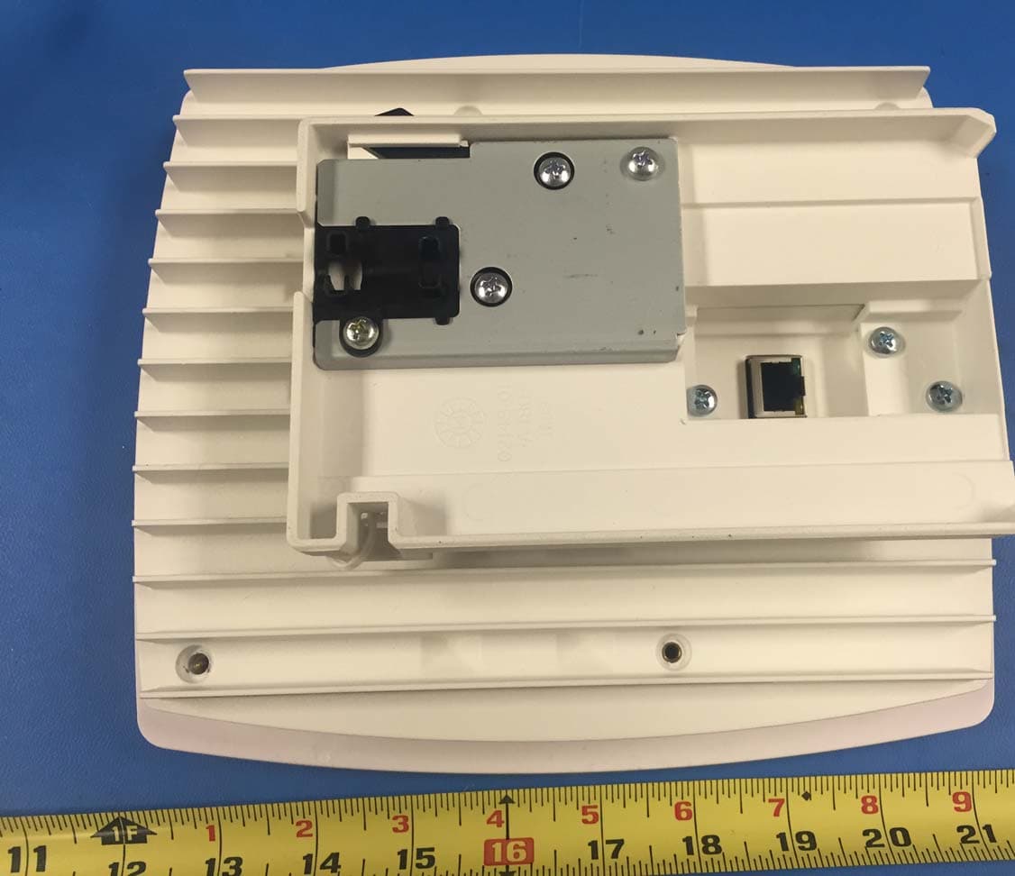
Y47RN310B4B2E
Oct 08, 2015SpiderCloud Radio Node
Equipment Class
PCB - PCS Licensed Transmitter
Y478718M24
May 14, 2015Universal Small Cell 8718
Equipment Class
PCB - PCS Licensed TransmitterY47RN310B7B2
Dec 21, 2014SpiderCloud Radio Node
Equipment Class
PCB - PCS Licensed Transmitter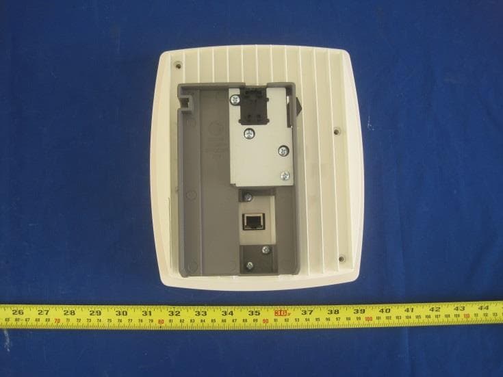
Y47RN310B4B13
Mar 30, 2014SpiderCloud Radio Node
Equipment Class
TNB - Licensed Non-Broadcast Station Transmitter