Y4B-ACM1110Arrayent Connect 900 Module
Arrayent Inc.
Click to zoom
Application Details
- Equipment Class
- DTS - Digital Transmission System
- Date of Grant
- Nov 07, 2013
- Application Purpose
- Original Equipment
- Date of Application
- Nov 07, 2013
- Equipment Note
- Arrayent Connect 900 Module
- Frequency Range
- 908.40000000 - 919.65000000
- Company
- Arrayent Inc.
- Country
- United States
Documents & Files
Document Text
Text extracted from the exhibit documents filed with the FCC. Open a document above to read the original.
Users Manual
ACM Data Sheet Version 1.3 Revision 3 November 7, 2013 ACM Data Sheet - November 7, 2013 - Version 1.3 Revision 3 Table of Contents 1 Overview.......................................................................................................................................................3 1.1 Description............................................................................................................................................3 1.2 Benefits.................................................................................................................................................3 1.3 Features................................................................................................................................................4 2 Hardware.......................................................................................................................................................4 2.1 Space Requirements.............................................................................................................................4 2.2 Pinout....................................................................................................................................................5 2.3 Electrical Characteristics......................................................................................................................8 2.4 UART Configuration..............................................................................................................................9 2.5 Antenna...............................................................................................................................................10 3 External Flash and SPI - Usage and Requirements...................................................................................10 4 SKU Nomenclature.....................................................................................................................................11 5 Label Nomenclature....................................................................................................................................11 6 ACM Development Kits and Additional Documentation.............................................................................11 7 FCC NOTICE...............................................................................................................................................12 8 IC NOTICE...................................................................................................................................................12 9 Document Information.................................................................................................................................13 9.1 Document Versioning..........................................................................................................................13 9.2 Revision History...................................................................................................................................14 2 ACM Data Sheet - November 7, 2013 - Version 1.3 Revision 3 1Overview The ACM (“Arrayent Connect Module”, “ACM”, or “Module” for short) is a family of surface-mount modules for enabling consumer products to communicate wirelessly to the Arrayent Connect Platform, a global Platform-as-a-Service (PaaS) for connected products. 1.1Description The ACM is physically composed of an integrated crystal, internal voltage regulator, matching circuitry, and filtering. The ACM is based on the CC1110 SoC from Texas Instruments. It measures 0.75 by 0.885 inches and is intended for use as a surface-mount module to be soldered on to the PCB of a consumer product. The ACM's energy-aware algorithms support long battery life. When powered by three AA batteries, the ACM by itself can sustain power for over twelve months. The ACM has received regulatory approval for modular devices in the United States (FCC), Canada (IC), and Europe (ETSI). 1.2Benefits The ACM has been optimized to connect low-cost consumer products to the Arrayent Connect Platform. Benefits include: •Fast time to market 3 ACM Data Sheet - November 7, 2013 - Version 1.3 Revision 3 •Low-power consumption: 2.2uA when sleeping, 165uA when operating normally •Minimal RF and computer networking experience necessary •100% RF-tested in production •Easy to implement on a two-layer PCB •Supports whole-house coverage (line of sight range: 150 meters, 10 dBm power output) •FCC 15.247a2 / 15.249, IC RSS-201 certified •Compliant with ETSI EN 300 328 1.3Features Features of the ACM include: •2.3V to 5.5V input •Three antenna options: external coaxial antenna, wire antenna via through-hole antenna port, and PCB antenna via ACM pin (PCB antenna option will require additional FCC certification testing) •Efficient UART interface •Operates in unlicensed ISM bands (915 MHz in United States, 868MHz in European Union) 2Hardware This chapter describes the various hardware requirements and characteristics of the ACM. 2.1Space Requirements The ACM is designed to be surface-mounted on a carrier board. The ACM requires 0.75 by 0.855 inches of space on your carrier board. 4 ACM Data Sheet - November 7, 2013 - Version 1.3 Revision 3 2.2Pinout The main interface between the ACM and the Client MCU are the electrical pins of the ACM. If a pin is not noted in the table below, then it should be considered reserved for internal use and should not be connected to the circuit of the carrier board. In the table below, direction is from the perspective of the ACM (input = client MCU ACM, output = → ACM client MCU).→ Pin #RequiredFunctionDirectionDescription 1-7, 14, 23, 34- 36, 37, xACM GroundConnected to carrier board ground. Best practice is to connect all pins to ground. At minimum, customer should connect one ground from each corner to 5 ACM Data Sheet - November 7, 2013 - Version 1.3 Revision 3 Pin #RequiredFunctionDirectionDescription 39ensure good coupling. 20xSPI_CS_NOutput/Hi-ZSPI S…
Text truncated - open the document above for the full version.
Block Diagram
ACM1110 Block Diagram CC1110 SoC Radio Balun 26Mhz Xtal 915Mhz, Q=1 I/O Pins Voltage Regulator
Cover Letter(s)
FCC Authorization May 10, 2013 FEDERAL COMMUNICATIONS COMMISSIONS Authorization and Evaluation Division 7435 Oakland Mills Road Columbia, MD 21046 Subject: Agent Authorization To whom it may concern: We Arrayent Incorporated, the undersigned, hereby authorizes Bay Area Compliance Laboratory Corporation to act on its behalf in all matters relating to application for Equipment authorization, including the signing of all documents relating to these matters. All acts carried out by Bay Area Compliance Laboratory Corporation on our behalf shall have the same effect as our own action. We, the undersigned, hereby certify that we are not subject to a denial of federal benefits, that includes FCC benefits, pursuant to Section 5301 of the Anti-Drug Abuse Act of 1988, 21 U.S.C. 853(a). This authorization is valid until further written notice from the applicant. Sincerely Yours, Shane Dyer, President Arrayent Incorporated 2317 Broadway Street Suite 20 Redwood City, CA 94063
Cover Letter(s)
FCC Confidential Authorization October 4, 2013 FEDERAL COMMUNICATIONS COMMISSIONS Authorization and Evaluation Division 7435 Oakland Mills Road Columbia, MD 21046 Subject: Confidentiality Request regarding application for certification of FCC ID: Y4B- ACM1110 In accordance with Sections 0.457 and 0.459 of the Commission’s Rules, Arrayent Incorporated hereby requests short-term confidential treatment of information accompanying this application as outlined below: • Internal Photos • External Photos • Test set-up photos • Users Manual • Circuit Descriptions, Schematics, and Block Diagrams The above materials contain proprietary and confidential information not customarily released to the public. The public disclosure of these materials provides unjustified benefits to its competitors in the market. Sincerely, Mr. Shane Dyer President Arrayent Incorporated 2317 Broadway Street Suite 20 Redwood City, CA 94063
Cover Letter(s)
Modular Approval Letter Date: October 3, 2013 The Device, FCC ID: Y4B-ACM1110, is seeking FCC authorization as a modular transmitter. The EUT meets the requirement for modular approval as detailed in FCC Public Notice DA 00- 1407. Compliance to each of the requirements is described below: 1. The modular transmitter does have its own RF shielding. 2. The modular transmitter does have buffered modulation/data inputs. 3. The modular transmitter does have its own power supply regulator 4. The modular transmitter complies with the antenna requirement of section 15.203 and 15.204(c) 5. The modular transmitter must be tested in a stand-alone configuration. Power will be supplied via a test fixture with the device fully exposed. The control for the device is available via a connector on the test fixture. 6. The modular transmitter must be labeled with its own FCC ID number 7. The modular transmitter must comply with any specific rule or operating requirements and the manufacturer must provide adequate instruction along with the module to explain any such requirements 8. The modular transmitter must comply with any applicable RF exposure requirements Sincerely, Mr. Shane Dyer President Arrayent Incorporated 2317 Broadway Street Suite 20 Redwood City, CA 94063
External Photos
Arrayent, Inc. FCC ID: Y4B-ACM1110; IC: 10122A-ACM1110 Report Number: R1304091-247 Page 44 of 46 FCC Part 15C/IC RSS-210 Test Report 15 Exhibit C – EUT Photographs 15.1 EUT – Top View 15.2 EUT – Bottom View Arrayent, Inc. FCC ID: Y4B-ACM1110; IC: 10122A-ACM1110 Report Number: R1304091-247 Page 45 of 46 FCC Part 15C/IC RSS-210 Test Report 15.3 EUT – Top View w/o Shielding 15.4 EUT – On Supporting Board View Arrayent, Inc. FCC ID: Y4B-ACM1110; IC: 10122A-ACM1110 Report Number: R1304091-247 Page 46 of 46 FCC Part 15C/IC RSS-210 Test Report 15.5 EUT – Antenna View (Wire) 15.6 EUT – Antenna View (Dipole) --- END OF REPORT ---
Internal Photos
Arrayent, Inc. FCC ID: Y4B-ACM1110; IC: 10122A-ACM1110 Report Number: R1304091-247 Page 44 of 46 FCC Part 15C/IC RSS-210 Test Report 15 Exhibit C – EUT Photographs 15.1 EUT – Top View 15.2 EUT – Bottom View Arrayent, Inc. FCC ID: Y4B-ACM1110; IC: 10122A-ACM1110 Report Number: R1304091-247 Page 45 of 46 FCC Part 15C/IC RSS-210 Test Report 15.3 EUT – Top View w/o Shielding 15.4 EUT – On Supporting Board View Arrayent, Inc. FCC ID: Y4B-ACM1110; IC: 10122A-ACM1110 Report Number: R1304091-247 Page 46 of 46 FCC Part 15C/IC RSS-210 Test Report 15.5 EUT – Antenna View (Wire) 15.6 EUT – Antenna View (Dipole) --- END OF REPORT ---
Operational Description
FCC ID: Y4B-ACM1110 FCC 15.247 Certification Information Operational Description 1. Circuit Principle: The ACM1110 product incorporates a Texas Instruments CC1110 system-on-chip radio transceiver. This implements a direct down conversion radio transceiver operating in the 900MHz ISM band. The maximum transmitter output power of this device is 10dBm. The AIC- EGW devices utilize a wideband digital modulation physical layer with the addition of a carrier sense multiple access (CSMA) medium access control (MAC) layer on each frequency channel. The data transmission rate is set to 100kpbs maximum. Modulation 2-FSK, 240Khz frequency deviation Radio Type Low-IF Super heterodyne Data rate 100kbps Radio IF Frequency 270.13Khz (fixed) Signal RF Bandwidth (6db) 540Khz Maximum transmit power 5dBm RF transmit frequencies 908.40 + 1.123*n MHz (where 0<=n<10) RF channel spacing 1123.54Khz Maximum packet size 1392 bits MAC protocol Carrier sense multiple access (CSMA) PHY protocol Digital modulation spread spectrum (>500Khz) Table 1 Transmitter Details of Operation Frequency channel Transmitter Base Channel frequency (MHz) Receiver Base Channel frequency (MHz) Frequency channel Transmitter Base Channel frequency (MHz) Receiver Base Channel frequency (MHz) 1 908.40 908.40 6 914.02 914.02 2 909.52 909.52 7 915.14 915.14 3 910.65 910.65 8 916.26 916.26 4 911.77 911.77 9 917.38 917.38 5 912.89 912.89 10 918.50 918.50 11 919.65 919.65 Table 2 Radio Frequency Channels 2. Radio Signal Flow and Baseband Operations: The Radio is based on the Texas Instrument CC1110 system-on-chip (SoC) module. The CC1110 features a low-IF receiver. The received RF signal is amplified by the low noise amplifier (LNA) and down-converted in quadrature (I and Q) to the intermediate frequency (IF). At IF, the I/Q signals are digitized by the ADCs. Automatic gain control (AGC), fine channel filtering, demodulation, and bit/packet synchronization is performed digitally. The transmitter part of the CC1110 is based on direct synthesis of the RF frequency. The frequency synthesizer includes a complete on-chip LC VCO and a 90 degrees phase shifter for generating the I and Q signals to the down-conversion. 3. Antenna: There are two supported antenna options Option 1: The module is a connected attached to a ¼ wavelength monopole. The antenna is permanently affixed to the PCB with a solder junction. Option 2: The antenna is connected through a coaxial connector on the PCB. The connector is a U.FL or compatible type. This supports a cabled connection to one of the validated third party antenna equipment types.
Schematics
C AIC-MOD Title Size Document Number Rev Date: Sheet of 1 2 B 01-FEB-2013 5 4 3 2 1 D C B A 1 2 3 4 5 A B C D Internet Connect Module 2. Power + CC1110 1. Title Sheet Schematic Pages Title Page FIDUCIAL FID1 FIDUCIAL FID2 FIDUCIAL FID3 SHIELD S1 BMIS-102 C Title Size Document Number Rev Date: Sheet of 2 2 B AIC-MOD 01-FEB-2013 5 4 3 2 1 D C B A 1 2 3 4 5 A B C D Battery Voltage Regulator CC1110 CC1110 Wire Antenna Pad Not Installed External Antenna (U.FL) Status LED Not Installed Bottom Solder Pads Off Module Pad C34 0.1uF C18 220pF R10 1% 56.0K CC1110Fx 2 DVDD 10 DVDD 28 DGUARD 29 DVDD 30 DCOUPL 19 AVDD 22 AVDD 25 AVDD 26 AVDD 14 P2_0 15 P2_1 16 P2_2 4 P1_0/LED 3 P1_1/LED 1 P1_2 36 P1_3 35 P1_4 34 P1_5 33 P1_6 32 P1_7 5 P0_0/ATEST 6 P0_1 7 P0_2 8 P0_3 9 P0_4 11 P0_5 12 P0_6 13 P0_7 31 NRESET 23 RF_P 24 RF_N 17 P2_3/XOSC32_O1 18 P2_4/XOSC32_O2 21 XOSC_O1 20 XOSC_O2 27 RBIAS 37 GND U4 CC1110Fx C11 0.1uF C15 0.1uF C12 0.1uF C14 0.01uF C13 2.2pF C17 0.01uF 1 UBAL 2 GND 3 BAL1 6 NC 5 GND 4 BAL2 U6 0896BM15A A1 C4 1.8pF L5 5.6nH C33 100pF FB1 1000 OHM R9 100K R8 100K C32 2.2uF C25 0.1uF 1 SIGNAL 2 GND 3 GND A2 U.FL-R-SMT FB2 1000 OHM 4 3 1 2 Y1 26.000Mhz C7 18pF C8 18pF R1 47 Ohm D1 LED P1 P2 P3 P4 P5 P6 P7 P8 P9 P10 P11 P12 P13 P14 P15 P16 P17 P18 P20 P21 P22 P19 C31 1000pF R7 2.7K C10 2.2uF P26 P23 P24 P25 P27 P28 P29 P30 P31 P32 P33 P34 P35 P36 P37 P38 1 GND 2 VIN 3 VOUT U2 MCP1700T-3302E P39 VCC_CC1110 VCC_CC1110 VCC_3.3 P1_4 P1_5 P1_3 P1_2 P0_0 P0_1 P0_2 P0_3 P0_4 P1_6 P0_6 P0_5 P1_0 P1_7 P1_1 P2_1 P2_2 P0_7 P2_0 P2_4 P2_3 P0_6 VBAT P2_4 VBAT P1_7 CC1110_NRESET P1_5 P1_6 P2_3 P2_4 P2_2 P0_7 P0_6 P0_4 P0_5 P0_3 P0_1 P0_2 P0_0 P1_0 P1_1 P1_2 P1_3 P1_4 P2_1 P2_0 CC1110_NRESET VCC_3.3 VCC_3.3
Test Report
Note: This test report is prepared for the customer shown above and for the device described herein. It may not be duplicated or used in part without prior written consent from Bay Area Compliance Laboratories Corp. This report must not be used by the customer to claim product certification, approval, or endorsement by A2LA*, NIST, or any agency of the Federal Government. * This report may contain data that are not covered by the A2LA accreditation and are marked with an asterisk “*” (Rev.2) FCC PART 15, SUBPART C IC RSS-210, ISSUE 8, DECEMBER 2010 TEST AND MEASUREMENT REPORT For Arrayent, Inc. 2317 Broadway Street, Suite 10, Redwood City, CA 94063, USA R e p o r t T y p e : O r i g i n a l R e p o r t P r o d u c t T y p e : 9 0 0 M H z R F M o d u l e Prepared By: Lionel Lara Report Number: R1304091-247 Report Date: 2013-10-30 Reviewed By: Victor Zhang RF/EMC Lead Bay Area Compliance Laboratories Corp. 1274 Anvilwood Avenue, Sunnyvale, CA 94089, USA Tel: (408) 732-9162 Fax: (408) 732-9164 FCC ID: Y4B-ACM1110 IC: 10122A-ACM1110 Arrayent, Inc. FCC ID: Y4B-ACM1110; IC: 10122A-ACM1110 Report Number: R1304091-247 Page 2 of 46 FCC Part 15C/IC RSS-210 Test Report TABLE OF CONTENTS 1 General Description ..................................................................................................................................................... 5 1.1 Product Description for Equipment Under Test (EUT) ...................................................................................... 5 1.2 Mechanical Description of EUT ......................................................................................................................... 5 1.3 Objective ............................................................................................................................................................. 5 1.4 Related Submittal(s)/Grant(s) ............................................................................................................................. 5 1.5 Test Methodology ............................................................................................................................................... 5 1.6 Measurement Uncertainty ................................................................................................................................... 5 1.7 Test Facility ........................................................................................................................................................ 6 2 System Test Configuration.......................................................................................................................................... 7 2.1 Justification ......................................................................................................................................................... 7 2.2 EUT Exercise Software....................................................................................................................................... 7 2.3 Special Equipment .............................................................................................................................................. 7 2.4 Equipment Modifications.................................................................................................................................... 7 2.5 Local Support Equipment ................................................................................................................................... 7 2.6 EUT Internal Configuration Details .................................................................................................................... 7 2.7 Interface Ports and Cables .................................................................................................................................. 7 2.8 Power Supply List and Details ............................................................................................................................ 7 3 Summary of Test Results ............................................................................................................................................ 8 4 FCC §15.247 (i), §2.1091 & IC RSS-102 – RF Exposure .......................................................................................... 9 4.1 Applicable Standard ............................................................................................................................................ 9 4.2 MPE Prediction ................................................................................................................................................. 10 4.3 MPE Results ..................................................................................................................................................... 10 5 FCC §15.203 & IC RSS-Gen §7.1.2 – Antenna Requirements ................................................................................ 11 5.1 Applicable Standard .......................................................................................................................................... 11 5.2 Antenna List ...................................................................................................................................................... 11 6 FCC §2.1051, §15.247(d) & IC RSS-210 §A8.5 – Spurious Emissions at Antenna Terminals .............................. 12 6.1 Applicable Standard .......................................................................................................................................... 12 6.2 Measurement Procedure.................................................................................................................................... 12 6.3 Test Equipment List and Details ....................................................................................................................... 12 6.4 Test Environmental Conditions .........................................................................…
Text truncated - open the document above for the full version.
Test Setup Photos
Arrayent, Inc. FCC ID: Y4B-ACM1110; IC: 10122A-ACM1110 Report Number: R1304091-247 Page 41 of 46 FCC Part 15C/IC RSS-210 Test Report 14 Exhibit B – Test Setup Photographs 14.1 Radiated Emission Front View (Wire Antenna) 14.2 Radiated Emission below 1 GHz Rear View (Wire Antenna) Arrayent, Inc. FCC ID: Y4B-ACM1110; IC: 10122A-ACM1110 Report Number: R1304091-247 Page 42 of 46 FCC Part 15C/IC RSS-210 Test Report 14.3 Radiated Emission above 1 GHz Rear View (Wire Antenna) 14.4 Radiated Emission Front View (Dipole Antenna) Arrayent, Inc. FCC ID: Y4B-ACM1110; IC: 10122A-ACM1110 Report Number: R1304091-247 Page 43 of 46 FCC Part 15C/IC RSS-210 Test Report 14.5 Radiated Emission below 1 GHz Rear View (Dipole Antenna) 14.6 Radiated Emission above 1 GHz Rear View (Dipole Antenna)
Contact Information
Applicant
Dustin McIntire(Systems Architect)
Test Firm
Bay Area Compliance Laboratories Corp.Lisa Tang
Technical Specifications
| # | Rule Parts | Frequency Range | Power Output |
|---|---|---|---|
| 1 | 15C | 908.4 MHz - 919.65 MHz | 2.76 mW |
Other Applications from Arrayent Inc.
Y4B-MST-RFM
Jul 25, 2012Monster Smart Power Module
Equipment Class
DTS - Digital Transmission System
Y4B-FAL-EGW
Feb 08, 2012Arrayent Internet Connect Ethernet Gateway
Equipment Class
DXX - Part 15 Low Power Communication Device Transmitter
Y4B-AIC-EGW
May 16, 2011Arrayent Internet Connect Ethernet Gatewa
Equipment Class
DTS - Digital Transmission System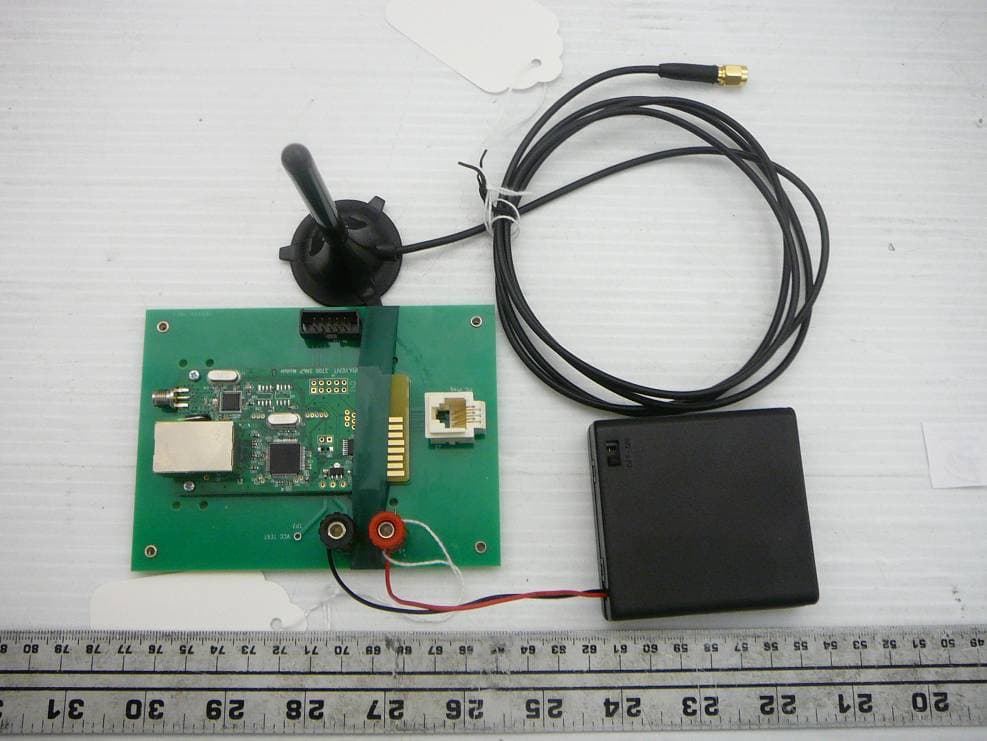
Y4B3700-SNMP
May 16, 20113700 RF/IP Card
Equipment Class
DTS - Digital Transmission System