Y4B-FAL-EGWArrayent Internet Connect Ethernet Gateway
Arrayent Inc.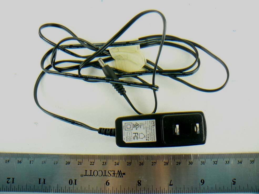
Click to zoom
Application Details
- Equipment Class
- DXX - Part 15 Low Power Communication Device Transmitter
- Date of Grant
- Feb 08, 2012
- Application Purpose
- Original Equipment
- Date of Application
- Feb 08, 2012
- Equipment Note
- Arrayent Internet Connect Ethernet Gateway
- Frequency Range
- 909.00000000 - 922.92000000
- Company
- Arrayent Inc.
- Country
- United States
Documents & Files
Document Text
Text extracted from the exhibit documents filed with the FCC. Open a document above to read the original.
Users Manual
Gateway User Manual FCC Notice This equipment has been tested and found to comply with the limits for a Class B digital device, pursuant to part 15 of the FCC Rules. These limits are designed to provide reasonable protection against harmful interference in a residential installation. This equipment generates, uses and can radiate radio frequency energy and, if not installed and used in accordance with the instructions, may cause harmful interference to radio communications. However, there is no guarantee that interference will not occur in a particular installation. If this equipment does cause harmful interference to radio or television reception, which can be determined by turning the equipment off and on, the user is encouraged to try to correct the interference by one or more of the following measures: • Reorient or relocate the receiving antenna. • Increase the separation between the equipment and receiver. • Connect the equipment into an outlet on a circuit different from that to which the receiver is connected. • Consult an experienced radio technician for help. FCC Warning Changes or modifications not expressly approved by the party responsible for compliance could void the user's authority to operate the equipment. FCC Radiation Exposure Statement To comply with FCC RF exposure compliance requirements, the antenna used for this transmitter must be installed to provide a separation distance of at least 20 cm from all persons and must not be co-located or operating in conjunction with any other antenna or transmitter. FCC Modular Approval Statement This equipment is sold only to OEM integrators and must be installed by the OEM or OEM integrators under the following conditions: 1) The antennas used for this transmitter must be installed to provide a separation distance of at least 20 cm from all persons and 2) The transmitter must not be co-located with any other antenna or transmitter. FCC Label This device complies with part 15 of the FCC Rules. Operation is subject to the following two conditions: (1) This device may not cause harmful interference, and (2) this device must accept any interference received, including interference that may cause undesired operation. Model: OLGATEWAY (Arrayent Inc.) FCC ID: Y4B-FAL-EGW IC: 10122A-FALEGW Introduction The ONELINK Gateway provides Internet connectivity to ONELINK Wireless Ecosystem products. The ONELINK Gateway utilizes Internet Protocol to connect to a central ONELINK server that provides the monitoring and control capability from any web browser. Features The ONELINK Gateway provides the following capabilities: • Simple and fast set up – no configuration required • Compatibility with most home and enterprise Internet routers • Internet connectivity to any web browser anywhere in the world • Wireless radio coverage of up to 5000 square feet of home or light commercial structures. This document describes how to install and use the ONELINK Gateway. Requirements Broadband connection In order to connect the ONELINK Gateway to the Internet, a broadband Internet connection will be required. Contact your local broadband connectivity provider to arrange for a connection to be installed if you do not have an Internet connection. IP infrastructure The ONELINK Gateway requires the following facility IP (Internet Protocol) infrastructure: • Broadband router or modem/router with available Ethernet connection (10 Megabits/second or better) on RJ-45 jack. Any home broadband router available in most electronic stores or provided by your broadband provider will work. Some enterprise class routers may require further configuration, refer to Appendix A for information in such situations. • DHCP (Dynamic Host Configuration Protocol) enabled in the router with IP Gateway and DNS (Domain Name System) server information must be configured. Any home broadband router will already have this service available. Some enterprise level routers will require configuration to enable this service. Tools No tools are required for installation. If you wish to mount the Ethernet Gateway on a surface or wall, double sided mounting tape may be used. Packing List Locate the following materials in the package: • ONELINK Gateway • DC power adapter (ONELINK Gateway requires 4.5 to 6V, 200mA power supply, with 2.5mm barrel connector, center positive). Equipment Description The ONELINK Gateway has the following physical features. Locate them in the accompanying diagram. 1) RJ-45 Ethernet jack 2) Power jack 3) Connection LED 4) Antenna Installation Location Prior to installation, find a suitable location for placing the ONELINK Gateway. Use the following recommendations to find such a location. • The ONELINK Gateway can cover a 5000 square foot wood construction (typical home) facility. This implies a circular coverage area of about 40 feet in radius. Place the ONELINK Gateway in a central location so that this 40 foot circle covers the entire facility. • If your facility is larger than this, consider using two or more ONELINK Gateways to provide adequate coverage. • Best wireless coverage is achieved by placing the ONELINK Gateway at least 3 feet above ground level. • Note that large concentrations of metal, such as home appliances, water heaters, fireplace hoods, or automobiles create a “radio shadow” which can disrupt wireless connectivity. Avoid placing the ONELINK Gateway near such obstacles. • If a wireless connection cannot be established between the ONELINK Gateway and a ONELINK Wireless Ecosystem product, try moving the ONELINK Gateway horizontally or vertically by a few feet. Moving the ONELINK Gateway will often shift “radio shadows” around, which may be preventing the wireless connection from working. Physical Installation Follow these steps to install the ONELINK Gateway. • Plug an Ethernet cable (CAT-5 or higher rated) into the RJ-45 Ethernet jack on the ONELINK Gateway. • Plug the other end of the Ethernet cable into an Internet router, or an Ethernet LAN that is c…
Text truncated - open the document above for the full version.
Block Diagram
OLGATEWAY Block Diagram CC1110 SoC Radio Balun 26Mhz Xtal 915Mhz, Q=1 Transformer RJ45 PIC18 MCU 25Mhz Xtal LDO Power Jack LED
External Photos
Arrayent, Inc. FCC ID: Y4B-FAL-EGW; IC: 10122A-FALEGW Report Number: R1112153-249 Page 35 of 39 FCC Part 15.249/IC RSS-210 Test Report 12 Exhibit C - EUT Photos 12.1 EUT Top View 12.2 EUT Button View Arrayent, Inc. FCC ID: Y4B-FAL-EGW; IC: 10122A-FALEGW Report Number: R1112153-249 Page 36 of 39 FCC Part 15.249/IC RSS-210 Test Report 12.3 EUT Front View 12.4 EUT Rear View Arrayent, Inc. FCC ID: Y4B-FAL-EGW; IC: 10122A-FALEGW Report Number: R1112153-249 Page 37 of 39 FCC Part 15.249/IC RSS-210 Test Report 12.5 EUT Side View 12.6 AC/DC Power Supply
ID Label/Location Info
Arrayent, Inc. FCC ID: Y4B-FAL-EGW; IC: 10122A-FALEGW Report Number: R1112153-249 Page 30 of 39 FCC Part 15.249/IC RSS-210 Test Report 10 Exhibit A – FCC & IC Equipment Labeling Requirements 10.1 FCC ID Label Requirements As per FCC §2.925, (a) Each equipment covered in an application for equipment authorization shall bear a nameplate or label listing the following: (1) FCC Identifier consisting of the two elements in the exact order specified in §2.926. The FCC Identifier shall be preceded by the term FCC ID in capital letters on a single line, and shall be of a type size large enough to be legible without the aid of magnification. Example: FCC ID: XXX123 Where: XXX—Grantee Code, 123—Equipment Product Code As per FCC §15.19, (a) In addition to the requirements in part 2 of this chapter, a device subject to certification, or verification shall be labeled as follows: (3) All other devices shall bear the following statement in a conspicuous location on the device: This device complies with part 15 of the FCC Rules. Operation is subject to the following two conditions: (1) This device may not cause harmful interference, and (2) this device must accept any interference received, including interference that may cause undesired operation. (4) Where a device is constructed in two or more sections connected by wires and marketed together, the statement specified above is required to be affixed only to the main control unit. If the EUT is integrated within another device then a label affixed to the host shall also state, “Contains FCC ID: XXXXXX” (5) When the device is so small or for such use that it is not practicable to place the statement specified under paragraph (a) of this section on it, the information required by this paragraph shall be placed in a prominent location in the instruction manual or pamphlet supplied to the user or, alternatively, shall be placed on the container in which the device is marketed. However, the FCC identifier or the unique identifier, as appropriate, must be displayed on the device. 10.2 IC Label Requirements As per IC RSS-Gen § 5, the certification number shall appear as follows: IC: XXXXXX-YYYYYYYY Where: • "XXXXXX-YYYYYYYY" is the certification number • "XXXXXX" is the Certificate Holder Number (CHN), made of at most 6 alphanumeric characters (A-Z, 0-9), assigned by Industry Canada; and • "YYYYYYYY" is the Unique Product Number (UPN), made of at most 11 alphanumeric characters (A-Z, 0-9) assigned by the applicant. • Note 1: The term "IC" before the equipment certification number only signifies that the Industry Canada technical specifications were met. • Note 2: Note 1 shall be conspicuously placed in the equipment user manual. • Note 3: Permitted alphanumeric characters used in the CHN and UPN are limited to capital letters (A-Z) and digits (0-9). Other characters, such as "#", "/" or "-", shall not be used. Arrayent, Inc. FCC ID: Y4B-FAL-EGW; IC: 10122A-FALEGW Report Number: R1112153-249 Page 31 of 39 FCC Part 15.249/IC RSS-210 Test Report 10.3 As per RSS-Gen §5.2 Equipment Labeling: Equipment subject to certification under the applicable RSS shall be permanently labeled on each item, or as an inseparable combination. The label must contain the following information for full compliance: (a) the certification number, prefixed by the term “IC:”; (b) the manufacturer's name, trade name or brand name; and (c) a model name or number. Equipment for which a certificate has been issued is not considered certified if it is not properly labeled. The information on the Canadian label can be combined with the manufacturer’s other labeling requirements. If the device size is too small to put a label, the label can be included in the user’s manual, upon agreement with Industry Canada. 10.4 FCC ID & IC Label Contents 10.5 FCC ID and IC Label Location Label here
Internal Photos
Arrayent, Inc. FCC ID: Y4B-FAL-EGW; IC: 10122A-FALEGW Report Number: R1112153-249 Page 38 of 39 FCC Part 15.249/IC RSS-210 Test Report 12.7 EUT Cover off View 12.8 EUT Main Board View - 1 Arrayent, Inc. FCC ID: Y4B-FAL-EGW; IC: 10122A-FALEGW Report Number: R1112153-249 Page 39 of 39 FCC Part 15.249/IC RSS-210 Test Report 12.9 EUT Main Board View - 2 --- END OF REPORT ---
Operational Description
FCC ID: Y4B-FAL-EGW MODEL: OLGATEWAY FCC 15.247 and 15.249 Certification Information Operational Description The Arrayent/First Alert Ethernet Gateway (EGW) provides Internet connectivity for an ecosystem of home security products using the Arrayent communications network. In addition the product is able to operate on the First Alert Onelink network (FCC ID reference M7U5001L). The EGW acts as a hub and access point for the wireless communications. As the wireless hub for these 900 MHZ wireless products, it manages frequency allocation and packet switching. As the access point it converts radio packets to Internet packets allowing monitoring and control of wireless products from the Internet. 1. Circuit Principle: The OLGATEWAY product incorporates a Texas Instruments CC1110 system-on-chip radio transceiver. This implements a direct down conversion radio transceiver operating in the 900MHz ISM band. The following sections describe the products operation in both it primary mode licensed under 15.247 and its secondary mode licensed under 15.249. Primary Operation The maximum transmitter output power of this device is 10dBm. The OLGATEWAY devices utilize a wideband digital modulation physical layer with the addition of a carrier sense multiple access (CSMA) medium access control (MAC) layer on each frequency channel. The data transmission rate is set to 100kpbs. Modulation 2-FSK, 240Khz frequency deviation Radio Type Low-IF Super heterodyne Data rate 100kbps Radio IF Frequency 270.13Khz (fixed) Signal RF Bandwidth (6db) 540Khz Maximum transmit power 10dBm RF transmit frequencies 908.40 + 1.123*n MHz (where 0<=n<=10) RF channel spacing 1123.54Khz Maximum packet size 1392 bits MAC protocol Carrier sense multiple access (CSMA) PHY protocol Digital modulation spread spectrum (>500Khz) Table 1 Transmitter Details of Operation Table 2 15.247 Radio Frequency Channels Secondary Operation When the gateway receives a command via its Internet connection, it will switch from the primary operation mode to the secondary mode of operation. This is accomplished by reprogramming the radio’s software registers to comply with the following radio specification: Modulation 2-FSK, 75Khz frequency deviation Radio Type Low-IF Super heterodyne Data rate 8.84kbps Radio IF Frequency 270.13Khz (fixed) Signal RF Bandwidth (6db) 200Khz Maximum transmit power 0dBm RF transmit frequencies 909.00 MHz, 913.32 MHz and 922.92 MHz Maximum packet size 104 bits MAC protocol Carrier sense multiple access (CSMA) When the gateway receives a command via its Internet connection, it will switch from the primary mode of operation to the secondary mode of operation. In this mode the gateway operates compliant with FCC Part 15.249. The maximum packet length while operating in the secondary mode is 13 bytes. 2. Radio Signal Flow and Baseband Operations: The Radio is based on the Texas Instrument CC1110 system-on-chip (SoC) module. The CC1110 features a low-IF receiver. The received RF signal is amplified by the low noise amplifier (LNA) and down-converted in quadrature (I and Q) to the intermediate frequency (IF). At IF, the I/Q signals are digitized by the ADCs. Automatic gain control (AGC), fine channel filtering, demodulation, and bit/packet synchronization is performed digitally. The transmitter part of the CC1110 is based on direct synthesis of the RF frequency. The frequency synthesizer includes a complete on-chip LC VCO and a 90 degrees phase shifter for generating the I and Q signals to the down-conversion. Frequency channel Transmitter Base Channel frequency (MHz) Receiver Base Channel frequency (MHz) Frequency channel Transmitter Base Channel frequency (MHz) Receiver Base Channel frequency (MHz) 1908.40908.406914.02914.02 2909.52909.527915.14915.14 3910.65910.658916.26916.26 4911.77911.779917.39917.39 5912.89912.8910918.51918.51 11919.65919.65 3. Antenna: The antenna is a permanently attached ¼ wavelength monopole. The antenna is permanently affixed to the PCB.
Schematics
AIC-EGW Title Size Document Number Rev Date: Sheet of 1 3 B Oct 12, 2011 H 5 4 3 2 1 D C B A 1 2 3 4 5 A B C D Internet Connect - Ethernet Gateway 2. CC1111 1. Title Sheet Schematic Pages Internet Connect Ethernet Gateway - Title Page 3. PIC18F67J60 ARRAYENT CONFIDENTIAL HOLE MTG MTG2.0MM HOLE MTG MTG2.0MM FIDUCIAL FIDUCIAL HOLE MTG MTG2.0MM FIDUCIAL HOLE MTG MTG2.0MM H AIC-EGW Title Size Document Number Rev Date: Sheet of 2 3 B Oct 12, 2011 5 4 3 2 1 D C B A 1 2 3 4 5 A B C D 3.3V Power Regulator CC1110 Status LED Internet Connect Ethernet Gateway - CC1110 Programming Interface Wire Antenna Pad Not Installed User Pushbutton ARRAYENT CONFIDENTIAL Not Installed R3 1% 56.0K C8 220pF R2 47 Ohm R4 10K C3 0.1uF D1 LED C4 0.1uF C18 0.1uF C32 1uF + 1 2 C1 20V 10uF FB1 1000 OHM 2 1 3 D4 BAT54C 2 3 1 J6 PJ-007 A1 C19 1.8pF L5 5.6nH C33 100pF J7 SMA C12 100pF 1 UBAL 2 GND 3 BAL1 6 NC 5 GND 4 BAL2 U5 0896BM15A C5 0.01uF C6 0.01uF C7 2.2pF C14 33pF C15 33pF CC1110Fx 2 DVDD 10 DVDD 28 DGUARD 29 DVDD 30 DCOUPL 19 AVDD 22 AVDD 25 AVDD 26 AVDD 14 P2_0 15 P2_1 16 P2_2 4 P1_0/LED 3 P1_1/LED 1 P1_2 36 P1_3 35 P1_4 34 P1_5 33 P1_6 32 P1_7 5 P0_0/ATEST 6 P0_1 7 P0_2 8 P0_3 9 P0_4 11 P0_5 12 P0_6 13 P0_7 31 NRESET 23 RF_P 24 RF_N 17 P2_3/XOSC32_O1 18 P2_4/XOSC32_O2 21 XOSC_O1 20 XOSC_O2 27 RBIAS 37 GND U1 CC1110Fx C9 0.1uF 1 2 Y1 26.000Mhz 1 2 SW1 TL1015 TP5 TP6 TP7 TP8 TP9 TP15 2 GND 3 VIN 1 VOUT U3 1722A33PXT VCC_3.3_CC1110 VCC_3.3_CC1110 VCC_3.3_CC1110 CC1110_STATUS_NLED0 VCC_3.3_CC1110 VCC_3.3 CC1110_NRESET CC1110_STATUS_NLED0 PIC_UART_TX PIC_UART_RX PIC_IRQ0 PIC_IRQ1 PIC_IRQ2 PIC_SCK PIC_CC1111_NCS PIC_MOSI PIC_MISO CC1110_DD CC1110_DC PIC_IRQ2 VCC_3.3_CC1110 CC1110_DD CC1110_DC CC1110_NRESET PIC_STATUS_LED2 PIC_STATUS_LED1 H AIC-EGW Title Size Document Number Rev Date: Sheet of 3 3 B Oct 12, 2011 5 4 3 2 1 D C B A 1 2 3 4 5 A B C D ICD Interface Ethernet RJ45 SPI SRAM or Flash - Optional Status LED Internet Connect Ethernet Gateway - PIC18F67JXX PIC18 Ethernet Production Pogo Testpoints ARRAYENT CONFIDENTIAL Not Installed Not Installed Bicolor Status LED EMI Filter NOT INSTALLED 1 RE1/P2C 2 RE0/P2D 3 RB0/INT0/FLT0 4 RB1/INT1 5 RB2/INT2 6 RB3/INT3 7 *MCLR 8 RG4/CCP5/P1D 9 VSS 10 VDDCORE/VCAP 11 RF7/*SS1 12 RF6/AN11 13 RF5/AN10/CVREF 14 RF4/AN9 15 RF3/AN8 16 RF2/AN7/C1OUT 17 RF1/AN6/C2OUT 18 ENVREG 19 AVDD 20 AVSS 21 RA3/AN3/VREF_ 22 RA2/AN2/VREF_ 23 RA1/LEDB/AN1 24 RA0/LEDA/AN0 25 VSS_1 26 VDD 27 RA5/AN4 28 RA4/T0CKI 29 RC1/T1OSI/ECCP2/P2A 30 RC0/T1OSO/T13CKI 31 RC6/TX1/CK1 32 RC7/RX1/DT1 33 RC2/ECCP1/P1A 34 RC3/SCK1/SCL1 35 RC4/SDI1/SDA1 36 RC5/SDO1 37 RB7/KBI3/PGD 38 VDD_1 39 OSC1/CLKI 40 OSC2/CLKO 41 VSS_2 42 RB6/KBI2/PGC 43 RB5/KBI1 44 RB4/KBI0 45 VSSRX 46 TPIN_ 47 TPIN__2 48 VDDRX 49 VDDTX 50 TPOUT_ 51 TPOUT__2 52 VSSTX 53 RBIAS 54 VDDPLL 55 VSSPLL 56 VSS_3 57 VDD_2 58 RD2/CCP4/P3D 59 RD1/ECCP3/P3A 60 RD0/P1B 61 RE5/P1C 62 RE4/P3B 63 RE3/P3C 64 RE2/P2B U2 PIC18F67J60 C2 0.1uF C10 0.1uF C20 0.1uF C21 0.1uF C23 1uF C24 0.1uF C25 0.1uF C22 0.1uF FB2 1000 OHM C26 0.1uF R5 2.26K TP10 R71 1% 49.9 OHM R8 1% 49.9 OHM R9 1% 49.9 OHM R10 1% 49.9 OHM FB3 60 OHM C31 0.1uF C34 0.1uF C44 0.1uF 4 GND 8 VCC 5 SI 1 NCS 6 SCK 2 SO 7 NHOLD U9 N25S830HA C28 0.1uF R6 10K R17 330 Ohm D7 LED R7 1M C16 33pF C17 33pF TP14 TP13 TP12 TP11 TP1 TP2 TP3 TP4 1 2 Y2 25.000Mhz R15 2.26K RX 1:1 TX 1:1 6 7 8 9 10 11 14 15 16 2 3 1 T1 TH015 RJ45 1 TXP 2 TXN 3 RXP 4 NC1 5 NC2 6 RXN 7 NC3 8 NC4 J1 NN3J0A023 R149 75 OHM R150 75 OHM R1 75 OHM R11 75 OHM C11 1000pF C13 56pF C27 56pF FB4 120 OHM FB5 120 OHM D2 R12 330 Ohm R13 330 Ohm VCORE VCC_3.3 AVCC_3.3 VCC_3.3 PIC_NRESET PIC_RB7 PIC_RB6 PIC_SCK PIC_MOSI PIC_MISO PIC_UART_TX PIC_UART_RX PIC_RAM_NCS PIC_CC1111_NCS PIC_TD+ PIC_TD- PIC_RD- PIC_RD+ VCC_3.3 PIC_RD- PIC_RD+ VCC_3.3 PIC_SCK PIC_MISO PIC_MOSI PIC_RAM_NCS PIC_STATUS_LED1 VCC_3.3 PIC_NRESET PIC_IRQ0 PIC_IRQ1 PIC_IRQ2 CC1110_NRESET PIC_STATUS_LED1 PIC_RB6 PIC_RB7 VCC_3.3 PIC_TD_FLT+ PIC_ETH_CT PIC_TD_FLT- PIC_RD+ PIC_RD- PIC_ETH_CT PIC_TD+ PIC_TD- PIC_STATUS_LED1 PIC_STATUS_LED2 PIC_STATUS_LED2
Test Report
Note: This test report is prepared for the customer shown above and for the device described herein. It may not be duplicated or used in part without prior written consent from Bay Area Compliance Laboratories Corp. This report must not be used by the customer to claim product certification, approval, or endorsement by NVLAP*, NIST, or any agency of the Federal Government. * This report may contain data that are not covered by the NVLAP accreditation and are marked with an asterisk “*” (Rev.2) FCC PART 15.249 IC RSS-210, ISSUE 8, DEC 2010 TEST AND MEASUREMENT REPORT For Arrayent, Inc. 2317 Broadway Street, Suite 140, Redwood City, CA 94063, USA FCC ID: Y4B-FAL-EGW IC: 10122A-FALEGW Report Type: Original Product Type: 900 MHz Low Power Transceiver Test Engineer: Ning Ma Report Number: R1112153-249 Report Date: 2012-01-31 Reviewed By: Victor Zhang EMC/RF Lead Prepared By: (84) Bay Area Compliance Laboratories Corp. 1274 Anvilwood Avenue, Sunnyvale, CA 94089, USA Tel: (408) 732-9162 Fax: (408) 732 9164 Arrayent, Inc. FCC ID: Y4B-FAL-EGW; IC: 10122A-FALEGW Report Number: R1112153-249 Page 2 of 39 FCC Part 15.249/IC RSS-210 Test Report TABLE OF CONTENTS 1 GENERAL INFORMATION ..................................................................................................................................... 5 1.1 PRODUCT DESCRIPTION FOR EQUIPMENT UNDER TEST (EUT)............................................................................. 5 1.2 MECHANICAL DESCRIPTION OF EUT ................................................................................................................... 5 1.3 OBJECTIVE........................................................................................................................................................... 5 1.4 RELATED SUBMITTAL(S)/GRANT(S) .................................................................................................................... 5 1.5 TEST METHODOLOGY.......................................................................................................................................... 5 1.6 MEASUREMENT UNCERTAINTY........................................................................................................................... 5 1.7 TEST FACILITY.................................................................................................................................................... 6 2 SYSTEM TEST CONFIGURATION ........................................................................................................................ 7 2.1 JUSTIFICATION..................................................................................................................................................... 7 2.2 EUT EXERCISE SOFTWARE.................................................................................................................................. 7 2.3 SPECIAL ACCESSORIES........................................................................................................................................ 7 2.4 EQUIPMENT MODIFICATIONS...............................................................................................................................7 2.5 LOCAL SUPPORT EQUIPMENT.............................................................................................................................. 7 2.6 EUT INTERNAL CONFIGURATION AND DETAILS.................................................................................................. 7 2.7 INTERFACE PORTS AND CABLING........................................................................................................................ 7 2.8 POWER SUPPLY AND LINE FILTERS...................................................................................................................... 7 3 SUMMARY OF TEST RESULTS ............................................................................................................................. 8 4 FCC §15.203 & IC RSS-GEN §7.1.2 – ANTENNA REQUIREMENTS ................................................................. 9 4.1 APPLICABLE STANDARD...................................................................................................................................... 9 4.2 RESULTS.............................................................................................................................................................. 9 5 FCC §15.207 & IC RSS-GEN §7.2.4 - CONDUCTED EMISSIONS....................................................................... 10 5.1 APPLICABLE STANDARD.................................................................................................................................... 10 5.2 TEST SETUP....................................................................................................................................................... 10 5.3 TEST PROCEDURE.............................................................................................................................................. 10 5.4 TEST SETUP BLOCK DIAGRAM........................................................................................................................... 11 5.5 CORRECTED AMPLITUDE & MARGIN CALCULATION......................................................................................... 11 5.6 TEST EQUIPMENT LIST AND DETAILS................................................................................................................ 12 5.7 TEST ENVIRONMENTAL CONDITIONS................................................................................................................. 12 5.8 SUMMARY OF TEST RESULTS............................................................................................................................. 12 5.9 CONDUCTED EMISSIONS TEST PLOTS AND DATA.............................................................................................. 13 6 FCC §15.249 (A) & IC RSS-210 §A2.9 – FIELD STRENGTH OF …
Text truncated - open the document above for the full version.
Test Setup Photos
Arrayent, Inc. FCC ID: Y4B-FAL-EGW; IC: 10122A-FALEGW Report Number: R1112153-249 Page 32 of 39 FCC Part 15.249/IC RSS-210 Test Report 11 Exhibit B – Test Setup Photographs 11.1 Conducted Emissions – Front View 11.2 Conducted Emissions – Side View Arrayent, Inc. FCC ID: Y4B-FAL-EGW; IC: 10122A-FALEGW Report Number: R1112153-249 Page 33 of 39 FCC Part 15.249/IC RSS-210 Test Report 11.3 Radiated Emissions (Below 1 GHz) – Front View 11.4 Radiated Emissions (Below 1 GHz) – Rear View Arrayent, Inc. FCC ID: Y4B-FAL-EGW; IC: 10122A-FALEGW Report Number: R1112153-249 Page 34 of 39 FCC Part 15.249/IC RSS-210 Test Report 11.5 Radiated Emissions (Above 1 GHz) – Rear View .
Contact Information
Applicant
Dustin McIntire(Systems Architect)
Test Firm
Bay Area Compliance LaboratoryJohn Chan
Technical Specifications
| # | Rule Parts | Frequency Range | Power Output |
|---|---|---|---|
| 1 | 15C | 909 MHz - 922.92 MHz | - |
Other Applications from Arrayent Inc.
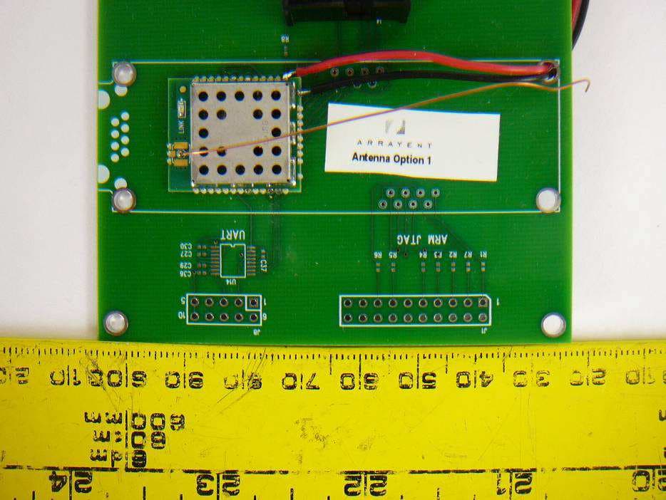
Y4B-ACM1110
Nov 07, 2013Arrayent Connect 900 Module
Equipment Class
DTS - Digital Transmission System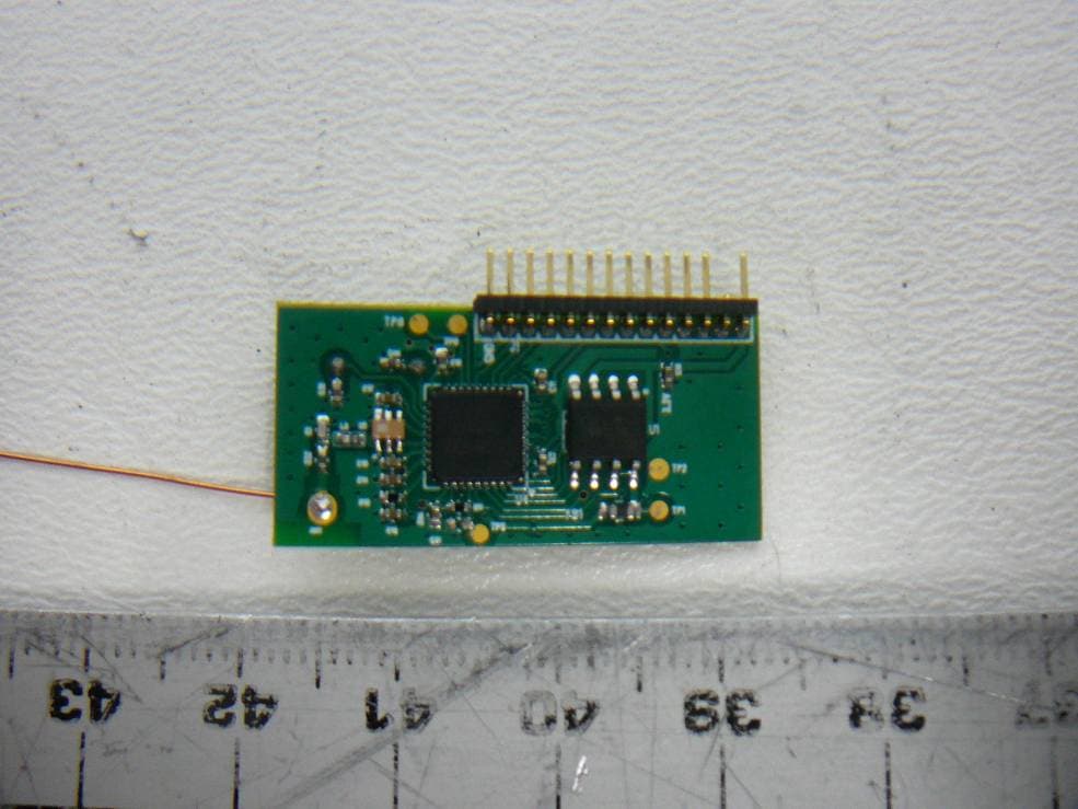
Y4B-MST-RFM
Jul 25, 2012Monster Smart Power Module
Equipment Class
DTS - Digital Transmission System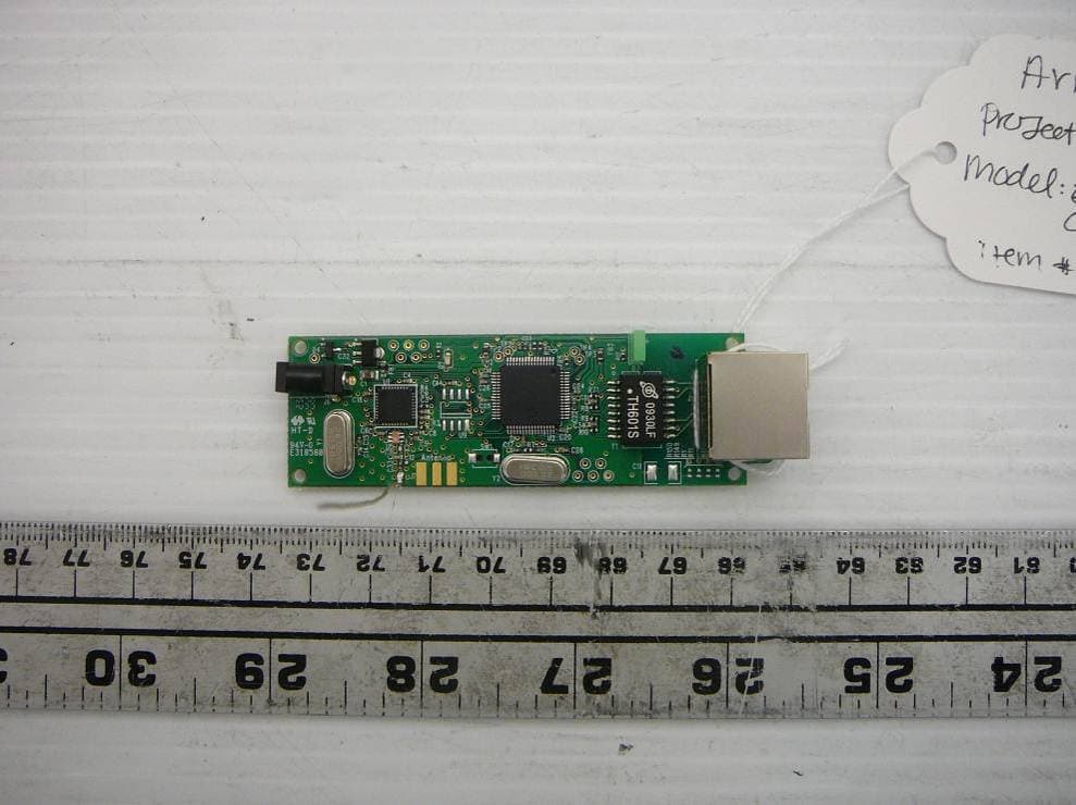
Y4B-AIC-EGW
May 16, 2011Arrayent Internet Connect Ethernet Gatewa
Equipment Class
DTS - Digital Transmission System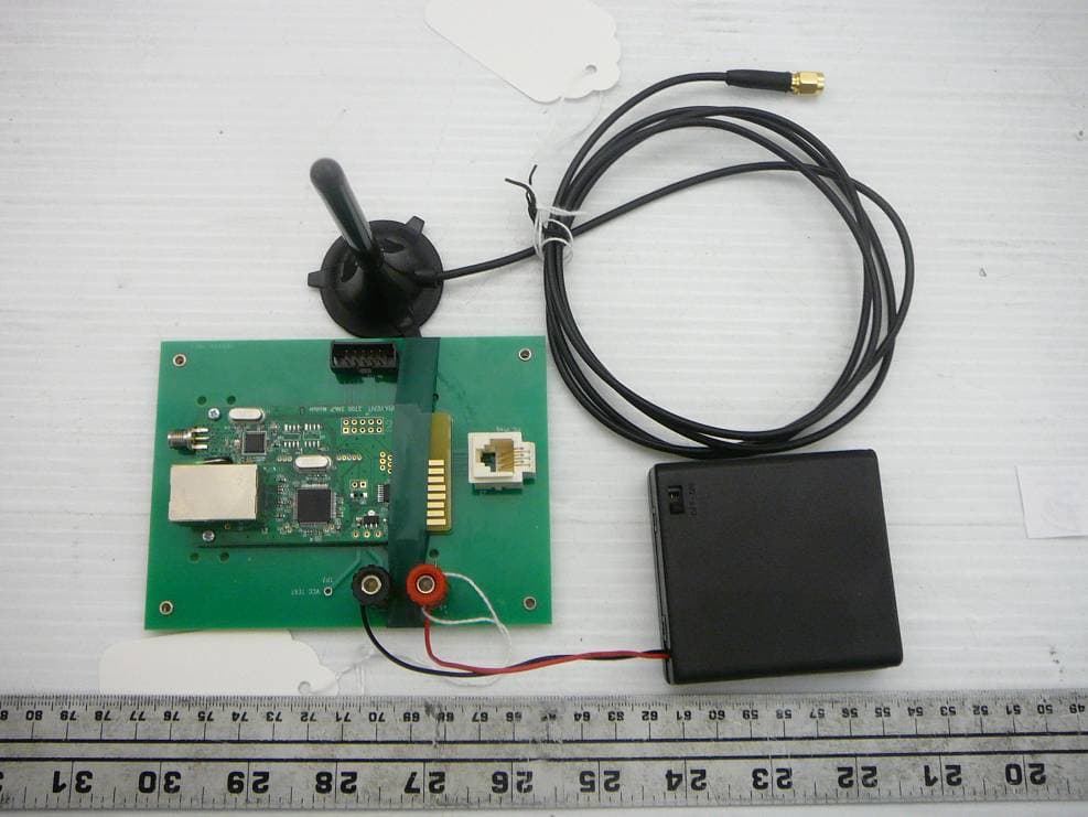
Y4B3700-SNMP
May 16, 20113700 RF/IP Card
Equipment Class
DTS - Digital Transmission System