Y4B-MST-RFMMonster Smart Power Module
Arrayent Inc.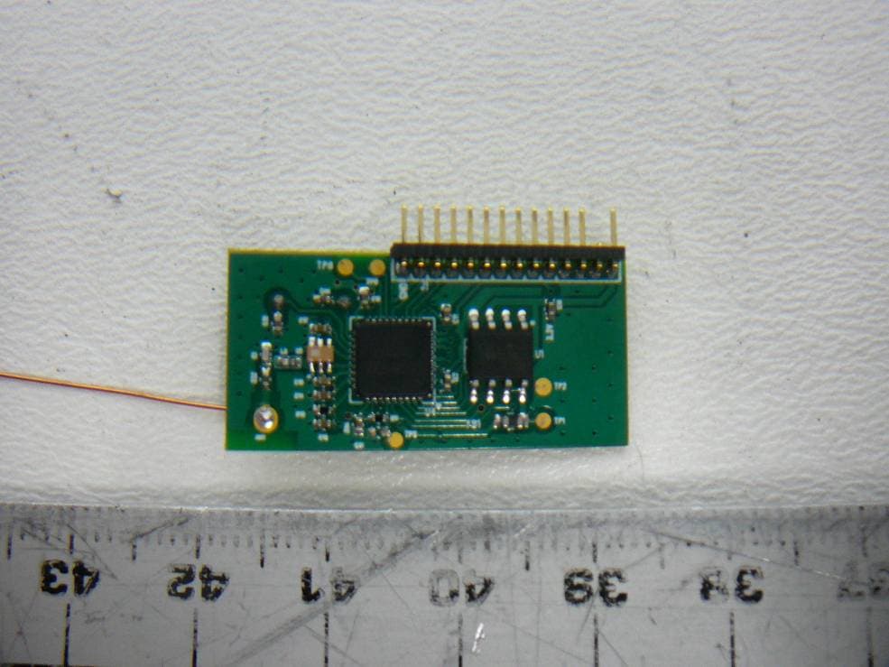
Click to zoom
Application Details
- Equipment Class
- DTS - Digital Transmission System
- Date of Grant
- Jul 25, 2012
- Application Purpose
- Original Equipment
- Date of Application
- Jul 25, 2012
- Equipment Note
- Monster Smart Power Module
- Frequency Range
- 908.56000000 - 919.80000000
- Company
- Arrayent Inc.
- Country
- United States
Documents & Files
Document Text
Text extracted from the exhibit documents filed with the FCC. Open a document above to read the original.
Users Manual
POWERCONTROL ™ ENGLISH 2 Free mobile app downloaded to your mobile device. The Gateway connects your PowerControl outlets to your mobile app via the Internet. Monster PowerControl 300MC. This is a 3-plug device. All 3 plugs protect whatever is plugged in from common power surges and spikes. All three of these plugs are monitored for energy usage, and one of them can be on/off controlled by the free mobile app. Monster Control AppMonster Control Gateway300MC* Basic PowerControl ™ Components ENGLISH 3 Monster PowerControl 100MC. This is a single plug device. Anything plugged into this device is protected from common power surges and spikes and can be monitored and on/off controlled from our free mobile app. Monster PowerControl 100M. This is a single plug device that protects whatever is plugged in from common power surges and spikes. You can also monitor your energy use from our free mobile app. * Different PowerControl Devices provide different features. Choose the device that’s right for your needs. • Protection from common power surges and spikes (All) • Monitoring power usage from the free mobile app (All) • Controlling on and off function from free mobile app (300MC and 100MC) 100MC*100M* ENGLISH 4 SAFETY PRECAUTIONS IMPORTANT SAFETY INFORMATION Please read and observe the following safety points at all times. WARNING—Power Sources Do not plug this PowerControl ™ into a power outlet that differs from the source indicated for safe use on the PowerControl. If you don’t know the type of electrical power that is supplied to your home, consult your local power company or a qualified electrician. WARNING—Grounding and Polarization A. Do not force your PowerControl plug into an outlet that is not designed to accept a three- wire grounded-type AC plug (a three-prong plug). This plug is designed to be inserted into a grounded-type outlet only. If this plug doesn’t fit directly inside your outlet, do not attempt to force it into the outlet. Never attempt to dismantle the plug in any way (or to alter the power cord). Do not attempt to defeat the grounding feature by using a 3-to-2 prong adapter. If you have questions about grounding, consult your local power company or a qualified electrician. B. If you use rooftop devices such as satellite dishes, antennas, or any other component with wire that connects to your PowerControl, be sure the wire(s) is properly grounded. This protects against voltage surges and static charges. C. Do not place any antenna near overhead power lines or any other power circuit. Do not touch any power line or power circuit. Doing so may cause severe physical injury or possibly death. WARNING—Liquid: Avoiding Electrical Shocks A. Do not operate your Monster PowerControl if liquid of any kind is spilled onto or inside the unit. B. Do not operate your Monster PowerControl near rain or water that’s spilled or contained (e.g., bathtub, or kitchen sink). WARNING—Power Cord Safety A. When routing your PowerControl’s AC power cord, do not place it near heavy foot traffic areas (e.g., hallways, doorways, and floors). Do not create a trip hazard with the power cord. B. If your power cord’s protective jacket begins to rip or fray, exposing the internal wiring, shielding, etc., disconnect it from the AC power source and discontinue use of the Monster PowerControl immediately. See the Warranty Information section of this owner’s manual for important details. ENGLISH 5 WARNING—No User Serviceable Parts Inside If, for any reason, your PowerControl is not operating properly, do not remove any part of the unit (cover, etc.) for repair. Unplug the unit and consult the Warranty Information section of this owner’s manual for important details. CAUTION—Exposure to Heat Do not expose your PowerControl to direct sunlight or place it near wall heaters, space heaters, or any enclosed space prone to temperature increase. CAUTION—Proper Cleaning In general, the only cleaning necessary for your Monster PowerControl is a light dusting. Unplug your component from the wall outlet before cleaning it. Do not use any type of liquid or aerosol cleaners. ENGLISH 6 FCC NOTICE FCC ID: Y4B-AIC-EGW (for PowerControl ™ Gateway) FCC ID: Y4B-MST-RFM (for PowerControl 100M / 100MC / 300MC) This equipment has been tested and found to comply with the limits for a Class B digital device, pursuant to part 15 of the FCC Rules. These limits are designed to provide reasonable protection against harmful interference in a residential installation. This equipment generates, uses and can radiate radio frequency energy and, if not installed and used in accordance with the instructions, may cause harmful interference to radio communications. However, there is no guarantee that interference will not occur in a particular installation. If this equipment does cause harmful interference to radio or television reception, which can be determined by turning the equipment off and on, the user is encouraged to try to correct the interference by one or more of the following measures: • Reorient or relocate the receiving antenna • Increase the separation between the equipment and receiver • Connect the equipment into an outlet on a circuit different from that to which the receiver is connected • Consult the dealer or an experienced radio/TV technician for help FCC Warning Changes or modifications not expressly approved by Monster Cable Products, Inc. could void the user’s authority to operate the equipment. FCC Radiation Exposure Statement To comply with FCC RF exposure compliance requirements, the antenna used for this transmitter must be installed to provide a separation distance of at least 20 cm from all persons and must not be co-located or operating in conjunction with any other antenna or transmitter. FCC Modular Approval Statement This equipment is sold only to OEM integrators and must be installed by the OEM or OEM integrators under the following conditions: 1. The antennas used for this transmitter must be installed to provide…
Text truncated - open the document above for the full version.
Block Diagram
MST-RFM Block Diagram CC1110 SoC Radio Balun 26Mhz Xtal 915Mhz, Q=1 Connector SPI Flash
Cover Letter(s)
FCC Confidential Authorization FEDERAL COMMUNICATIONS COMMISSIONS Authorization and Evaluation Division 7435 Oakland Mills Road Columbia, MD 21046 Subject: Confidentiality Request regarding application for certification of FCC ID: Y4B-MST- RFM In accordance with Sections 0.457 and 0.459 of the Commission’s Rules, Arrayent Incorporated hereby requests short-term confidential treatment of information accompanying this application as outlined below: • Internal Photos • External Photos • Test set-up photos • Users Manual • Circuit Descriptions, Schematics, and Block Diagrams The above materials contain proprietary and confidential information not customarily released to the public. The public disclosure of these materials provides unjustified benefits to its competitors in the market. Sincerely, President Arrayent Incorporated 1017 El Camino Real #417 Redwood City, CA 94063
Cover Letter(s)
Modular Approval Letter Date: July 6, 2012 The Device, FCC ID: Y4B-MST-RFM, is seeking FCC authorization as a modular transmitter. The EUT meets the requirement for modular approval as detailed in FCC Public Notice DA 00- 1407. Compliance to each of the requirements is described below: 1. The modular transmitter must have its own RF shielding. Shie lding will be provided by the end product to comply with the emissions requirements. 2. The modular transmitter does have buffered modulation/data inputs. 3. The modular transmitter does have its own power supply regulator 4. The modular transmitter complies with the antenna requirement of section 15.203 and 15.204(c) 5. The modular transmitter must be tested in a stand-alone configuration. Power will be supplied via a test fixture with the device fully exposed. The control for the device is available via a connector on the test fixture. 6. The modular transmitter must be labeled with its own FCC ID number 7. The modular transmitter must comply with any specific rule or operating requirements and the manufacturer must provide adequate instruction along with the module to explain any such requirements 8. The modular transmitter must comply with any applicable RF exposure requirements Sincerely, Shane Dyer, President Arrayent Incorporated 1017 El Camino Real #417 Redwood City, CA 94063
External Photos
Arrayent Inc. FCC ID: Y4B-MST-RFM, IC: 10122A-MSTRFM Report Number: R1205141-247 Page 50 of 52 FCC Part 15C/IC RSS-210 Test Report 16 Exhibit C – EUT Photographs 16.1 EUT – Top View 16.2 EUT – Bottom View Arrayent Inc. FCC ID: Y4B-MST-RFM, IC: 10122A-MSTRFM Report Number: R1205141-247 Page 51 of 52 FCC Part 15C/IC RSS-210 Test Report 16.3 Support Equipment – Programming Board Top View 16.4 Support Equipment – Programming Board Bottom View Arrayent Inc. FCC ID: Y4B-MST-RFM, IC: 10122A-MSTRFM Report Number: R1205141-247 Page 52 of 52 FCC Part 15C/IC RSS-210 Test Report 16.5 Support Equipment – CC Debugger View 16.6 Battery View --- END OF REPORT ---
ID Label/Location Info
Arrayent Inc. FCC ID: Y4B-MST-RFM, IC: 10122A-MSTRFM Report Number: R1205141-247 Page 44 of 52 FCC Part 15C/IC RSS-210 Test Report 14 Exhibit A – FCC & IC Equipment Labeling Requirements 14.1 FCC ID Label Requirements As per FCC §2.925, (a) Each equipment covered in an application for equipment authorization shall bear a nameplate or label listing the following: (1) FCC Identifier consisting of the two elements in the exact order specified in §2.926. The FCC Identifier shall be preceded by the term FCC ID in capital letters on a single line, and shall be of a type size large enough to be legible without the aid of magnification. Example: FCC ID: XXX123 Where: XXX—Grantee Code, 123—Equipment Product Code As per FCC §15.19, (a) In addition to the requirements in part 2 of this chapter, a device subject to certification, or verification shall be labeled as follows: (3) All other devices shall bear the following statement in a conspicuous location on the device: This device complies with part 15 of the FCC Rules. Operation is subject to the following two conditions: (1) This device may not cause harmful interference, and (2) this device must accept any interference received, including interference that may cause undesired operation. (4) Where a device is constructed in two or more sections connected by wires and marketed together, the statement specified above is required to be affixed only to the main control unit. If the EUT is integrated within another device then a label affixed to the host shall also state, “Contains FCC ID: XXXXXX” (5) When the device is so small or for such use that it is not practicable to place the statement specified under paragraph (a) of this section on it, the information required by this paragraph shall be placed in a prominent location in the instruction manual or pamphlet supplied to the user or, alternatively, shall be placed on the container in which the device is marketed. However, the FCC identifier or the unique identifier, as appropriate, must be displayed on the device. 14.2 IC Label Requirements As per IC RSS-Gen §5.2, the certification number shall appear as follows: IC: XXXXXX-YYYYYYYY Where: • "XXXXXX-YYYYYYYY" is the certification number • "XXXXXX" is the Certificate Holder Number (CHN), made of at most 6 alphanumeric characters (A-Z, 0-9), assigned by Industry Canada; and • "YYYYYYYY" is the Unique Product Number (UPN), made of at most 11 alphanumeric characters (A-Z, 0-9) assigned by the applicant. • Note 1: The term "IC" before the equipment certification number only signifies that the Industry Canada technical specifications were met. • Note 2: Note 1 shall be conspicuously placed in the equipment user manual. • Note 3: Permitted alphanumeric characters used in the CHN and UPN are limited to capital letters (A-Z) and digits (0-9). Other characters, such as "#", "/" or "-", shall not be used. Arrayent Inc. FCC ID: Y4B-MST-RFM, IC: 10122A-MSTRFM Report Number: R1205141-247 Page 45 of 52 FCC Part 15C/IC RSS-210 Test Report As per RSS-Gen §5.2 Equipment Labeling: Equipment subject to certification under the applicable RSS, shall be permanently labeled on each item, or as an inseparable combination. The label must contain the following information for full compliance: (a) the certification number, prefixed by the term “IC:”; (b) the manufacturer's name, trade name or brand name; and (c) a model name or number. Equipment for which a certificate has been issued is not considered certified if it is not properly labeled. The information on the Canadian label can be combined with the manufacturer’s other labeling requirements. If the device size is too small to put a label, the label can be included in the user’s manual, upon agreement with Industry Canada. 14.3 FCC ID & IC Label Contents and Location on EUT Label here
Internal Photos
Arrayent Inc. FCC ID: Y4B-MST-RFM, IC: 10122A-MSTRFM Report Number: R1205141-247 Page 50 of 52 FCC Part 15C/IC RSS-210 Test Report 16 Exhibit C – EUT Photographs 16.1 EUT – Top View 16.2 EUT – Bottom View
Operational Description
FCC ID: Y4B-MST-RFM FCC 15.247 Certification Information Operational Description 1. Circuit Principle: The MST-RFM product incorporates a Texas Instruments CC1110 system-on-chip radio transceiver. This implements a direct down conversion radio transceiver operating in the 900MHz ISM band. The maximum transmitter output power of this device is 10dBm. The AIC- EGW devices utilize a wideband digital modulation physical layer with the addition of a carrier sense multiple access (CSMA) medium access control (MAC) layer on each frequency channel. The data transmission rate is set to 100kpbs maximum. Modulation 2-FSK, 240Khz frequency deviation Radio Type Low-IF Super heterodyne Data rate 100kbps Radio IF Frequency 270.13Khz (fixed) Signal RF Bandwidth (6db) 540Khz Maximum transmit power 9dBm RF transmit frequencies 908.56 + 1.123*n MHz (where 0<=n<=10) RF channel spacing 1123.54Khz Maximum packet size 1392 bits MAC protocol Carrier sense multiple access (CSMA) PHY protocol Digital modulation spread spectrum (>500Khz) Table 1 Transmitter Details of Operation Frequency channel Transmitter Base Channel frequency (MHz) Receiver Base Channel frequency (MHz) Frequency channel Transmitter Base Channel frequency (MHz) Receiver Base Channel frequency (MHz) 1 908.56 908.56 6 914.17 914.17 2 909.68 909.68 7 915.29 915.29 3 910.81 910.81 8 916.41 916.41 4 911.93 911.93 9 917.54 917.54 5 913.05 913.05 10 918.66 918.66 11 919.80 919.80 Table 2 Radio Frequency Channels 2. Radio Signal Flow and Baseband Operations: The Radio is based on the Texas Instrument CC1110 system-on-chip (SoC) module. The CC1110 features a low-IF receiver. The received RF signal is amplified by the low noise amplifier (LNA) and down-converted in quadrature (I and Q) to the intermediate frequency (IF). At IF, the I/Q signals are digitized by the ADCs. Automatic gain control (AGC), fine channel filtering, demodulation, and bit/packet synchronization is performed digitally. The transmitter part of the CC1110 is based on direct synthesis of the RF frequency. The frequency synthesizer includes a complete on-chip LC VCO and a 90 degrees phase shifter for generating the I and Q signals to the down-conversion. 3. Antenna: The antenna is a permanently attached ¼ wavelength monopole. The antenna is permanently affixed to the PCB.
RF Exposure Info
Arrayent Inc. FCC ID: Y4B-MST-RFM, IC: 10122A-MSTRFM Report Number: R1205141-247 Page 9 of 52 FCC Part 15C/IC RSS-210 Test Report 4 FCC §15.247 (i), §2.1091 & IC RSS-102 – RF Exposure 4.1 Applicable Standard According to FCC §15.247(i), §1.1307(b)(1) and §1.1310 systems operating under the provisions of this section shall be operated in a manner that ensures that the public is not exposed to radio frequency energy level in excess of the Commission’s guidelines. Limits for General Population/Uncontrolled Exposure Frequency Range (MHz) Electric Field Strength (V/m) Magnetic Field Strength (A/m) Power Density (mW/cm 2 ) Averaging Time (minutes) Limits for General Population/Uncontrolled Exposure 0.3-1.34 614 1.63 * (100) 30 1.34-30 824/f 2.19/f * (180/f 2 ) 30 30-300 27.5 0.073 0.2 30 300-1500 / / f/1500 30 1500-100,000 / / 1.0 30 f = frequency in MHz * = Plane-wave equivalent power density Before equipment certification is granted, the procedure of IC RSS-102 must be followed concerning the exposure of humans to RF fields. According to IC RSS-102 Issue 2 section 4.1, RF limits used for general public will be applied to the EUT. Frequency Range (MHz) Electric Field (V/m rms) Magnetic Field (A/m rms) Power Density (W/m 2 ) Time Averaging (min) 0.003 - 1 280 2.19 - 6 1 - 10 280 / f 2.19 / f - 6 10 - 30 28 2.19 / f - 6 30 – 300 28 0.073 2* 6 300 – 1 500 1.585 f 0.5 0.0042 f 0.5 f / 150 6 1 500 – 15 000 61.4 0.163 10 6 15 000 – 150 000 61.4 0.163 10 616000 / f 1.2 150 000- 300 000 0.158 f 0.5 4.21 x 10 -4 f 0.5 6.67 x 10 -5 f 616000 / f 1.2 Note: ƒ is frequency in MHz * = Power density limit is applicable at frequencies greater than 100 MHz Arrayent Inc. FCC ID: Y4B-MST-RFM, IC: 10122A-MSTRFM Report Number: R1205141-247 Page 10 of 52 FCC Part 15C/IC RSS-210 Test Report 4.2 MPE Prediction Predication of MPE limit at a given distance, Equation from OET Bulletin 65, Edition 97-01 S = PG/4πR² Where: S = power density P = power input to antenna G = power gain of the antenna in the direction of interest relative to an isotropic radiator R = distance to the center of radiation of the antenna 4.3 MPE Results Maximum peak output power at antenna input terminal (dBm):8.95 Maximum peak output power at antenna input terminal (mW): 7.852 Prediction distance (cm): 20 Prediction frequency (MHz): 914.17 Maximum Antenna Gain, typical (dBi): 7.2 Maximum Antenna Gain (numeric): 5.25 Power density of prediction frequency at 20.0 cm (mW/cm 2 ):0.0082 Power density of prediction frequency at 20.0 cm (W/m 2 ):0.082 MPE limit for uncontrolled exposure at prediction frequency (mW/cm 2 ):0.609 MPE limit for uncontrolled exposure at prediction frequency (W/m 2 ):6.09 The device is compliant with the requirement MPE limit for uncontrolled exposure. The maximum power density at the distance of 20 cm is 0.0082 mW/cm 2 (0.082 W/m 2 ).Limit is 0.609 mW/cm 2 (6.09 W/m 2 ).
Schematics
A MST-RFM Title Size Document Number Rev Date: Sheet of 1 2 B Jan 29, 2012 Arrayent Inc. Power Cube - CC1110 Design LAYOUT NOTES: 2. Use common pin numbering for all SOT-23 packages 1. No vias inside SMT caps and resistors. 2. CC1110 1. Title Sheet Schematic Pages A B C D 5 4 3 2 1 D C B A 1 2 3 4 5 Message Bear - Title Page Power Cube - Title Page ARRAYENT CONFIDENTIAL A MST-RFM Title Size Document Number Rev Date: Sheet of 2 2 B Jan 29, 2012 Arrayent Inc. CC1110 A B C D 5 4 3 2 1 D C B A 1 2 3 4 5 SPI Flash Programming Interface Power Cube - CC1110 Monopole Wire Antenna Pad Optional for firmware update ARRAYENT CONFIDENTIAL C34 0.1uF C18 220pF FB1 BLM18AG102SN1D C31 1000pF R10 1% 56.0K CC1110Fx 2 DVDD 10 DVDD 28 DGUARD 29 DVDD 30 DCOUPL 19 AVDD 22 AVDD 25 AVDD 26 AVDD 14 P2_0 15 P2_1 16 P2_2 4 P1_0/LED 3 P1_1/LED 1 P1_2 36 P1_3 35 P1_4 34 P1_5 33 P1_6 32 P1_7 5 P0_0/ATEST 6 P0_1 7 P0_2 8 P0_3 9 P0_4 11 P0_5 12 P0_6 13 P0_7 31 NRESET 23 RF_P 24 RF_N 17 P2_3/XOSC32_O1 18 P2_4/XOSC32_O2 21 XOSC_O1 20 XOSC_O2 27 RBIAS 37 GND U4 CC1110Fx C11 0.1uF C15 0.1uF C12 0.1uF C14 0.01uF C13 2.2pF C35 0.1uF C30 18pF C17 0.01uF 4 GND 8 VCC 3 NWP 7 NHOLD 5 SI 1 NCS 6 SCK 2 SO U1 MX25L8005 1 UBAL 2 GND 3 BAL1 6 NC 5 GND 4 BAL2 U5 0896BM15A A1 C33 100pF 1 2 Y1 26.000Mhz TP8 TP9 TP5 1 1 2 2 3 3 4 4 5 5 6 6 7 7 8 8 9 9 10 10 11 11 12 12 13 13 14 14 J1 HEADER 14 R11 10K C29 18pF L5 5.6nH C3 1.8pF TP1 TP2 VCC_CC1110 VCC_CC1110 VCC_CC1110 VCC_3.3 VCC_3.3 MPU_NRESET SPI_SDO SPI_SCK FLASH_NCS SPI_SDI VCC_3.3 MPU_DD MPU_DC RESET_OUT UNUSED1 SPI2_CS MPU_LED2 MPU_LED1 MPU_AC_PWR_DIS MPU_AC_PWR_EN FLASH_NCS SPI_SCK SPI_SDI SPI_SDO BTN_IRQ SPI2_CLK UNUSED2 SPI2_SDI SPI2_SDO CLK_OUT MPU_DC MPU_DD MPU_NRESET VCC_3.3 BTN_IRQ CLK_OUT MPU_AC_PWR_DIS MPU_AC_PWR_EN RESET_OUT SPI2_CS SPI2_CLK SPI2_SDO SPI2_SDI MPU_LED2 MPU_LED1 VCC_3.3
Test Report
Note: This test report is prepared for the customer shown above and for the device described herein. It may not be duplicated or used in part without prior written consent from Bay Area Compliance Laboratories Corp. This report must not be used by the customer to claim product certification, approval, or endorsement by A2LA*, NIST, or any agency of the Federal Government. * This report may contain data that are not covered by the A2LA accreditation and are marked with an asterisk “*” (Rev.2) FCC PART 15 SUBPART C IC RSS-210, ISSUE 8, DECEMBER 2010 TEST AND MEASUREMENT REPORT For Arrayent Inc. 1017 El Camino Real #417, Redwood City, CA 94063, USA Report Type: Original Report Product Type: 900 MHz Transceiver Module Prepared By: Quinn Jiang Report Number: R1205141-247 Report Date: 2012-07-12 Reviewed By: Victor Zhang EMC/RF Lead Bay Area Compliance Laboratories Corp. 1274 Anvilwood Avenue Sunnyvale, CA 94089, USA Tel: (408) 732-9162 Fax: (408) 732-9164 FCC ID: Y4B-MST-RFM IC: 10122A-MSTRFM Arrayent Inc. FCC ID: Y4B-MST-RFM, IC: 10122A-MSTRFM Report Number: R1205141-247 Page 2 of 52 FCC Part 15C/IC RSS-210 Test Report TABLE OF CONTENTS 1 General Description..................................................................................................................................................... 5 1.1 Product Description for Equipment Under Test (EUT) ....................................................................................... 5 1.2 Mechanical Description of EUT .......................................................................................................................... 5 1.3 Objective.............................................................................................................................................................. 5 1.4 Related Submittal(s)/Grant(s) .............................................................................................................................. 5 1.5 Test Methodology................................................................................................................................................ 5 1.6 Measurement Uncertainty.................................................................................................................................... 5 1.7 Test Facility......................................................................................................................................................... 6 2 System Test Configuration.......................................................................................................................................... 7 2.1 Justification.......................................................................................................................................................... 7 2.2 EUT Exercise Software ....................................................................................................................................... 7 2.3 Special Equipment ............................................................................................................................................... 7 2.4 Equipment Modifications .................................................................................................................................... 7 2.5 Local Support Equipment .................................................................................................................................... 7 2.6 EUT Internal Configuration Details .................................................................................................................... 7 2.7 Interface Ports and Cabling ................................................................................................................................. 7 3 Summary of Test Results ............................................................................................................................................ 8 4 FCC §15.247 (i), §2.1091 & IC RSS-102 – RF Exposure.......................................................................................... 9 4.1 Applicable Standard ............................................................................................................................................ 9 4.2 MPE Prediction.................................................................................................................................................. 10 4.3 MPE Results ...................................................................................................................................................... 10 5 FCC §15.203 & IC RSS-Gen §7.1.2 – Antenna Requirements ................................................................................ 11 5.1 Applicable Standard .......................................................................................................................................... 11 5.2 Results ............................................................................................................................................................... 11 6 FCC §15.207 & IC RSS-Gen §7.2.4 – AC Line Conducted Emissions.................................................................... 12 6.1 Applicable Standards ......................................................................................................................................... 12 6.2 Test Setup .......................................................................................................................................................... 12 6.3 Test Procedure ................................................................................................................................................... 12 6.4 Test Setup Block Diagram................................................................................................................................. 13 6.5 Corrected Amplitude & Margin Calculation ...........................................................…
Text truncated - open the document above for the full version.
Test Setup Photos
Arrayent Inc. FCC ID: Y4B-MST-RFM, IC: 10122A-MSTRFM Report Number: R1205141-247 Page 46 of 52 FCC Part 15C/IC RSS-210 Test Report 15 Exhibit B – Test Setup Photographs 15.1 AC Line Conducted Emission Front View 15.2 AC Line Conducted Emission Side View Arrayent Inc. FCC ID: Y4B-MST-RFM, IC: 10122A-MSTRFM Report Number: R1205141-247 Page 47 of 52 FCC Part 15C/IC RSS-210 Test Report 15.3 TX Radiated Emission Front View at 3m 15.4 TX Radiated Emission below 1 GHz Rear View at 3m Arrayent Inc. FCC ID: Y4B-MST-RFM, IC: 10122A-MSTRFM Report Number: R1205141-247 Page 48 of 52 FCC Part 15C/IC RSS-210 Test Report 15.5 TX Radiated Emission above 1 GHz Rear View at 3m 15.6 RX Radiated Emission Front View at 3m (Note: Programming board is not required after configuration) Arrayent Inc. FCC ID: Y4B-MST-RFM, IC: 10122A-MSTRFM Report Number: R1205141-247 Page 49 of 52 FCC Part 15C/IC RSS-210 Test Report 15.7 RX Radiated Emission below 1 GHz Rear View at 3m 15.8 RX Radiated Emission above 1 GHz Rear View at 3m (Note: Programming board is not required after configuration)
Contact Information
Applicant
Dustin McIntire(Systems Architect)
Test Firm
Bay Area Compliance LaboratoryJohn Chan
Technical Specifications
| # | Rule Parts | Frequency Range | Power Output |
|---|---|---|---|
| 1 | 15C | 908.56 MHz - 919.8 MHz | 78.50 mW |
Other Applications from Arrayent Inc.
Y4B-ACM1110
Nov 07, 2013Arrayent Connect 900 Module
Equipment Class
DTS - Digital Transmission System
Y4B-FAL-EGW
Feb 08, 2012Arrayent Internet Connect Ethernet Gateway
Equipment Class
DXX - Part 15 Low Power Communication Device Transmitter
Y4B-AIC-EGW
May 16, 2011Arrayent Internet Connect Ethernet Gatewa
Equipment Class
DTS - Digital Transmission System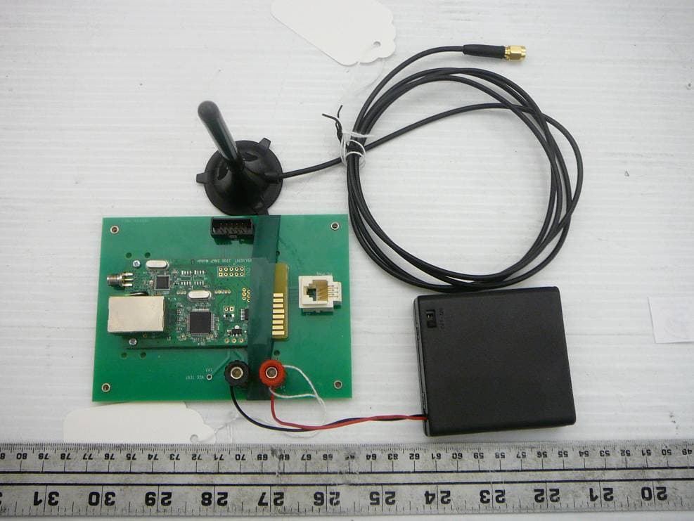
Y4B3700-SNMP
May 16, 20113700 RF/IP Card
Equipment Class
DTS - Digital Transmission System