Y5DTPMS203-CANBUSTPMS-CANBUS
VALOR HONG KONG COMPANY LIMITED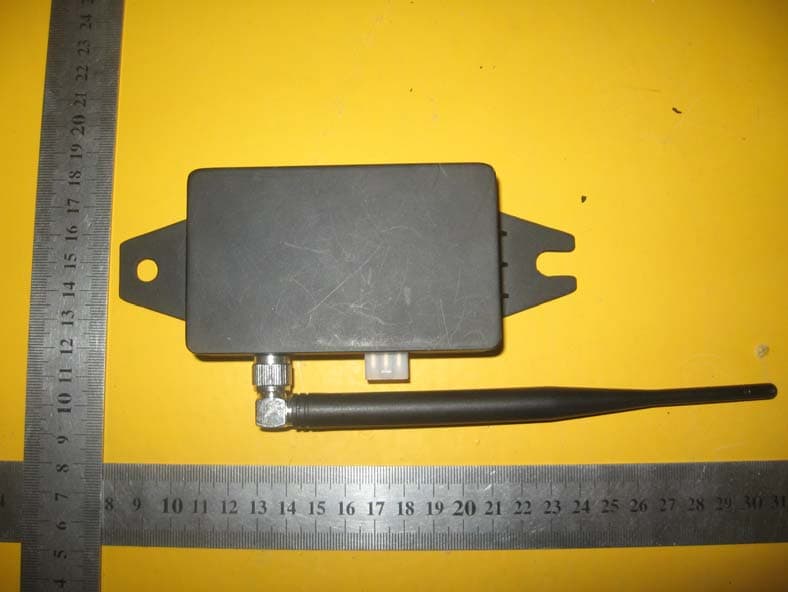
Click to zoom
Application Details
- Equipment Class
- DSR - Part 15 Remote Control/Security Device Transceiver
- Date of Grant
- Jan 12, 2011
- Application Purpose
- Original Equipment
- Date of Application
- Jan 09, 2011
- Equipment Note
- TPMS-CANBUS
- Frequency Range
- 433.92000000 - 433.92000000
- Country
- Hong Kong
Documents & Files
Document Text
Text extracted from the exhibit documents filed with the FCC. Open a document above to read the original.
Users Manual
CAN module 1 CANBUS USER MANUAL 1.1. REQUIREMENTS 1.1.1. PHYSICAL REQUIREMENTS The module shall be compatible with various types of power supply for different commercial vehicles, mainly 12V and 24V. Normal operating conditions: • Operating temperature: -40°C—+85°C; • Relative humidity: 45%—75%; • Pressure: 86Kpa—106Kpa(absolute pressure value); • Storage temperature range:-40°C—+85°C. 1.1.2. FUNCTION REQUIREMENT CAN module shall be able to receive, process, analyze, store and transmit data from the sensors and the tool. Its main functions are as follows: • Reliable data receiving: the receiving rate shall > 90% • Time setting • Data storage • Serial Port data transmission • Sensor ID registration The module communicates with TPMS Smart Tool and realizes ID LEARNING. After TPMS is started, the CAN module will transmit its ID to TPMS Smart Tool by RF. Then the Sensor ID of each tire will be learned by TPMS Smart Tool. All the Sensors ID and CAN module ID in the TPMS Smart Tool are transmitted to CANBUS again for registration. Besides, the data of pressure and temperature of tires will be transmitted by CANBUS, not by RF. 1.1.3. PROPERTIES REQUIREMENT • Reverse polarity requirements: after one-minute connection of reverse polarity, the product shall be able to function properly with normal power supply; • Receiver’s contact discharge level is 8KV, air discharge level is 15KV. 1.2. CAN MODULE PRINCIPLE CAN module is used to receive wireless information, and appropriately process and display information. Main parts and functions of CAN module are: • R/F receiver module decodes high frequency signal transmitted by tractor’s transmitting module and transceiver module; then it sends the data package to MCU through SPI port. • MCU analyzes data information in the data package. In the case of tire pressure sensor signal, sensor ID will be analyzed. If sensor ID is the same with its predetermined ID information, its temperature and pressure information will be collected and processed; once sensor ID is different with its predetermined ID information, the data will not be considered as that vehicle’s tire data and will not be processed. • Power system will change 12V or 24V vehicle power supply into normal operating voltages for different modules. CAN module 2 • Memory module records tire information stored by the receiver (if any abnormality occurred in any tire, the tire information will be immediately stored), the data can be downloaded to a computer through Serial Port or wirelessly for analysis. 1.3. CAN MODULE PERFORMANCE DISCRIPTION 1.3.1. MODULE INTERFACE CIRCUIT AND INSTALLATION DIMENSION Note: ANT is antenna interface. Wire is extended to vehicle chassis. Length of wire is defined by vehicle manufacturer according to different vehicle models. 1.3.2. DEFINITION OF PORT z CAN BUS port: Socket type: MOLEX 39-01-2060 or 5569-06AIS(corresponding plug model as 39-01-2060 or 5557-06R) 6pin Definition of pin: z RF port: REVERSE SMA port (90° angle) 5 pin 2 pin 3 pin 6pin GND (black) VIN(DC24/12V compatible, red) CANH(yellow) CANL(green) CAN module 3 1.3.3. FUNCTIONS 1.3.3.1. HIGH PRESSURE WARNING When tire pressure is≥10.8Bar(8.3*1.3), high pressure warning level two, potential risky status, driver shall stop the vehicle and adjust tire pressure immediately. When tire pressure is≥9.5Bar(8.3*1.15), high pressure warning level one, it calls driver’s attention to tire pressure and adjust tire pressure accordingly. 1.3.3.2. LOW PRESSURE WARNING When tire pressure is < 7.4Bar(8.3*0.9), low pressure warning level one, it calls driver’s attention to tire pressure and adjust tire pressure accordingly. When tire pressure is< 6.6Bar(8.3*0.8), low pressure warning level two, potential risky status, driver shall stop the vehicle and adjust tire pressure immediately. 1.3.3.3. HIGH TEMPERATURE WARNING: When tire pressure is≥80°C, it gives out high temperature warning, driver shall stop the vehicle and lower the temperature of the tire. 1.3.3.4. FAST LEAKAGE WARNING: When the tire pressure loss is ≥0.33Bar within 16s, it gives out fast leakage warning, driver shall stop the vehicle and make appropriate treatment. 1.3.3.5. NON-RECEIVING DATA WARNING: When the system does not receive tire pressure information for more than 20 minutes, it gives out non- receiving data warning. 1.3.3.6. CAN BUS COMMUNICATIONS When any of the above 5 kinds of information is received, the system will send data to ICM through CAN BUS for processing. 1.3.3.7. DATA STORAGE The system can store 4300 of tire information. Under normal conditions, data shall be stored every 30 minutes; under abnormal condition, data shall be stored every 10s. When abnormality occurs in any tire, the stored information shall be reviewed. The function is similar to Black Box. 1.3.3.8. ID LEARNING The module communicates with TPMS Smart Tool and realizes ID LEARNING; To make integration of TPMS to vehicles simple, save installation time, our proposed installation process is as follows: CAN module 4 1.3.3.9. CAN BUS COMMUNICATIONS PROTOCOL • CAN BUS communications protocol is based on J1939 • Transmission rate: 250Kbits/S • CAN2.0B, Extended Super Frame • Recommend circuit: Note:The load resistor (marked R223)whether to need depends on the CAN bus design. • Communications time sequence: 1)Under normal conditions: All tire data are transmitted every 10S after the first data is received; the time interval between every two tires is 100ms. st ar t Sensors preparati on Sensor installed onto wheels write tire ID and location into receivin g module by TPMS smart tool Tires installati on Use tool, read tire ID, establish one- to-one relationship between tire ID and tire location Test End Tires installation line Chassis installatio n line Receivin g module installati on Body instal lation line wiring CAN module 5 2)Under abnormal conditions: When an abnormal data is received, it will be transferred through CAN BUS immediately. 3)Under abnormal conditions: All abnormal …
Text truncated - open the document above for the full version.
Cover Letter(s)
VALOR HONG KONG COMPANY LIMITED 3905 TWO EXCHANGE SQUARE 8 CONNAUGHT PLACE CENTRAL HK Hong Kong Authority letter Date: 2010-12-20 FCC ID: Y5DTPMS203-CANBUS American Telecommunications Certification Body, Inc. 6731 Whittier Avenue Suite C110 McLean, VA 22101 To Whom It May Concern: WORLD STANDARDIZATION CERTIFICATION & TESTING CO., LTD. Laboratory is authorized to act on our behalf, until otherwise notified, for applications to American Telecommunications Certification Body, Inc. (ATCB). We certify that we are not subject to denial of federal benefits, that includes FCC benefits, pursuant to Section 5301 of the Anti-Drug Abuse Act of 1988, U.S.C. 862. Further, no party, as defined in 47 CFR 1.2002 (b) to the application is subject to denial of federal benefits, that includes FCC benefits. Thank you. Regards, Albert Fan 3905 TWO EXCHANGE SQUARE 8 CONNAUGHT PLACE CENTRAL HK Hong Kong Authority letter Tel: (086)21-57690000 Fax: (086)21-57690035
Cover Letter(s)
VALOR HONG KONG COMPANY LIMITED 3905 TWO EXCHANGE SQUARE 8 CONNAUGHT PLACE CENTRAL HK Date: 2010-12-20 FCC ID: Y5DTPMS203-CANBUS American Telecommunications Certification Body, Inc. 6731 Whittier Avenue Suite C110 McLean, VA 22101 Request for Confidentiality Pursuant to Sections 0.457 and 0.459 of the commissions rules, we hereby request that the following documents be held confidential: (List here the documents for which you are seeking confidentiality – for example ...) • Schematics • Block diagram These materials contain trade secrets and proprietary information and are not customarily released to the public. The public disclosure of this information might be harmful to the company and provide unjustified benefits to our competitors. Thank you. Regards, Albert Fan 3905 TWO EXCHANGE SQUARE 8 CONNAUGHT PLACE CENTRAL HK Tel: (086)21-57690000 Fax: (086)21-57690035
External Photos
EXTERIOR PHOTOGRAPHS
ID Label/Location Info
FCC ID: Y5DTPMS203-CANBUS Label Location on EUT Label: FCC ID: Y5DTPMS203-CANBUS This device complies with Part 15 of the FCC Rules. Operation is subject to the following two conditions: (1)this device may not cause harmful interference, and (2)this device must accept any interference received, including interference that may cause undesired operation. MADE IN CHINA
Internal Photos
INTERIOR PHOTOGRAPHY
Operational Description
TPMS203-CANBUS Specification TEST ITEM TEST CONDITION UNIT Typical LIMIT DC operating voltage V 24 9—30 DC current drain Standby Arm mA 15 18 max. Transmitting mA 18 22 max. Transmitting/Receiving frequency MHz 433.92 +/-85KHz Modulation mode FSK Receiving sensitivity dBm -105 -95 max. Once the device was powered, the device will transmit the CANBUS's ID information to TPMS Smart tool automatically, the data transmission will be stopped after 120ms. The TPMS smart tool got the CANBUS ID and stored in EPPROM, then the smart tool goes to learn all sensor's ID from tires by RF, after all the sensor and CANBUS's ID are located in the TPMS smart tool, the TPMS smart tool will send these information to CANBUS for registration. Power conversion circuit converts input power into each module’s working electric level. RF receiving circuit receives RF signals and sends to MCU after decoding. MCU analyzes received signal, pick up the tires sensor IDs and compare the IDs with those reserved in the EEPROM. If the IDs are consistent, the MCU continues to check the pressure and temperature data and send these data through 6pins CANBUS wires to vehicle’s display system to display. MCU is the core part of a CANBUS receiver, processing all the data.
Test Report
FCC ID: MKFARI59 Page 1 FCC ID TEST REPORT for TPMS-CANBUS Trade Mark: N/A Model: 203 Test Report Number:WSCT10120412E-1 Issued Date:December 26, 2010 Issued for VALOR HONG KONG COMPANY LIMITED 3905 TWO EXCHANGE SQUARE 8 CONNAUGHT PLACE CENTRAL HK Issued by: WORLD STANDARDIZATION CERTIFICATION & TESTING CO., LTD. Building A, Baoshi Road, Baoshi Science & Technology Park, Bao'an District, Shenzhen, Guangdong, China TEL: +86-755-26996192 FAX: +86-755-26996253 Note: This report shall not be reproduced except in full, without the written approval of World Standardization Certification& Testing CO., LTD. This document may be altered or revised by World Standardization Certification& Testing CO., LTD. personnel only, and shall be noted in the revision section of the document. The test results in the report only apply to the tested sample. Report reference No.:WSCT10120412E-1 Issued:December 26, 2010 Revised:None TRF No.:FCC PART 15C-15.231/A0 Page 2 of 21 FCC ID: Y5DTPMS203-CANBUS This report shall not be reproduced except in full, without the written approval of World Standardization Certification & Testing CO., LTD. Revision History of report Rev. Issue No. Revisions Effect Page Revised By 00 WSCT10120412E-1 Initial Issue ALL Kallen Wang Report reference No.:WSCT10120412E-1 Issued:December 26, 2010 Revised:None TRF No.:FCC PART 15C-15.231/A0 Page 3 of 21 FCC ID: Y5DTPMS203-CANBUS This report shall not be reproduced except in full, without the written approval of World Standardization Certification & Testing CO., LTD. TABLE OF CONTENTS 1 TEST RESULT CERTIFICATION .............................................................................................. 4 2 TEST RESULT SUMMARY ....................................................................................................... 5 3 EUT DESCRIPTION ................................................................................................................... 6 4 TEST METHODOLOGY ............................................................................................................. 7 4.1 DECISION OF FINAL TEST MODE ......................................................................................................... 7 4.2 EUT SYSTEM OPERATION ................................................................................................................... 7 5 SETUP OF EQUIPMENT UNDER TEST ...................................................................................... 8 5.1 DESCRIPTION OF SUPPORT UNITS ................................................................................................... 8 5.2 CONFIGURATION OF SYSTEM UNDER TEST .................................................................................... 8 6 FACILITIES AND ACCREDITATIONS ........................................................................................ 9 6.1 FACILITIES ............................................................................................................................................. 9 6.2 ACCREDITATIONS ................................................................................................................................. 9 6.3 MEASUREMENT UNCERTAINTY .......................................................................................................... 9 7 CONDUCTED EMISSION MEASUREMENT ............................................................................. 10 7.4 TEST SETUP ......................................................................................................................................... 11 7.5. TEST RESULTS .................................................................................................................................... 11 8 RADIATED EMISSION MEASUREMENT ............................................................................... 12 8.1 LIMITS OF RADIATED EMISSION MEASUREMENT ........................................................................... 12 8.2 TEST INSTRUMENTS .......................................................................................................................... 13 8.3 TEST PROCEDURES ........................................................................................................................... 13 8.4 TEST SETUP ........................................................................................................................................ 14 8.5 TEST RESULTS .................................................................................................................................... 15 9 20DB OCCUPIED BANDWIDTH MEASUEMENT ................................................................. 16 10 DWELL TIME MEASUREMENT .......................................................................................... 18 11. ANTENNA REQUIREMENT .................................................................................................. 21 Report reference No.:WSCT10120412E-1 Issued:December 26, 2010 Revised:None TRF No.:FCC PART 15C-15.231/A0 Page 4 of 21 FCC ID: Y5DTPMS203-CANBUS This report shall not be reproduced except in full, without the written approval of World Standardization Certification & Testing CO., LTD. 1 TEST RESULT CERTIFICATION Product: TPMS-CANBUS Model: 203 Trade Mark: N/A Applicant: VALOR HONG KONG COMPANY LIMITED 3905 TWO EXCHANGE SQUARE 8 CONNAUGHT PLACE CENTRAL HK Factory Shanghai Qunying Auto Electronics Co., Ltd. 5500 Shenzhuan Rd., Dongjing, Songjiang, Shanghai 201619, China. Tested Date: December 16-18,2010 Test Voltage: DC 12V/DC 24V APPLICABLE STANDARDS STANDARD TEST RESULT FCC PART 15C No non-compliance noted ANSI C63.4: 2003 No non-compliance noted Note: 1. The test result judgment is decided by the limit of measurement standard 2. The information of measurement uncertainty is available upon the customer’s request. Deviation from Applicable Standard None The above equipment has been tested by World Standardization Certification & Testing Co., Ltd and found co…
Text truncated - open the document above for the full version.
Test Setup Photos
TEST SETUP PHOTOGRAPHY Radiation Emission:
Contact Information
Applicant
Albert Fan(Manager)
Technical Contact
WORLD STANDARDIZATION CERTIFICATION & TESTING CO.,
[email protected]86-755-26996192
Building A, Baoshi Road, · Shenzhen · China
Test Firm
World Standardization Certification&TestingCO.,LTDKelly Wu
Technical Specifications
| # | Rule Parts | Frequency Range | Power Output |
|---|---|---|---|
| 1 | 15.231(e) | 433.92 MHz - 433.92 MHz | - |
Other Applications from VALOR HONG KONG COMPANY LIMITED
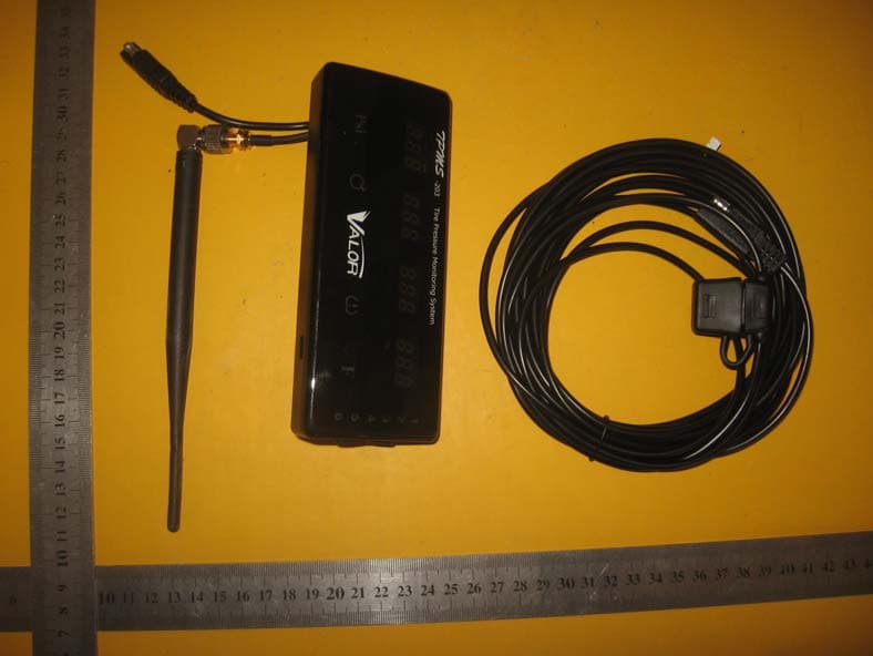
Y5DTPMS203-RD
Jan 12, 2011TPMS-RD
Equipment Class
CYY - Communications Receiver used w/Pt 15 Transmitter
Y5DTPMS203-SENSOR
Jan 12, 2011TPMS-SENSOR
Equipment Class
DSC - Part 15 Security/Remote Control Transmitter