Y5DTPMS203-SENSORTPMS-SENSOR
VALOR HONG KONG COMPANY LIMITED
Click to zoom
Application Details
- Equipment Class
- DSC - Part 15 Security/Remote Control Transmitter
- Date of Grant
- Jan 12, 2011
- Application Purpose
- Original Equipment
- Date of Application
- Jan 11, 2011
- Equipment Note
- TPMS-SENSOR
- Frequency Range
- 433.92000000 - 433.92000000
- Country
- Hong Kong
Documents & Files
Document Text
Text extracted from the exhibit documents filed with the FCC. Open a document above to read the original.
Users Manual
SENSOR USER MANAUL TABLE OF CONTENTS 1.1 INTRODUCTION ................................................................................................................................ 3 1.2 WORKING MODE .............................................................................................................................. 3 1.2.1 NORMAL PRESSURE INSPECTING ............................................................................................................. 3 1.2.2 LOW PRESSURE WARNING MODE ............................................................................................................. 3 1.3 INSTALLATION TRANSMITTER ....................................................................................................... 4 1.3.1 INSTALLATION TRANSMITTER ............................................................................................................................... 4 1.3.2 INSTALLATION ID MODULE .................................................................................................................................... 7 1.3.3 REMOVING TRANSMITTER .................................................................................................................................... 9 1.4 PARAMETERS OF THE PRODUCTS ............................................................................................... 9 1.5 FCC's authentication announcement ........................................................................................... 10 1.6 European regulations announcements ........................................................................................ 10 1.7 CE directive announcement .......................................................................................................... 10 3 1.1 INTRODUCTION 11.1 1 1.2 WORKING MODE 1.2.1 NORMAL PRESSURE INSPECTING If the pressure and temperature of tire is normal, the transmitter will send pressure and temperature data every 30 seconds. 1.2.2 LOW PRESSURE WARNING MODE If the pressure of tire is between 0.66 Bar and 4 Bar, the transmitter will send pressure and temperature data every 12 seconds. Transmitter: Mounted inside the tyre on the centre of wheel using cradle and steel strap to continuously monitor tyre’s pressure and temperature every 10-second and transmit data via RF to the integrated display at 30-second intervals when tyres are normal or 12-second when the tyres are abnormal. Stainless Steel Strap: Tyre transmitters are mounted to the surface of the rim using a stainless steel strap which can be installed on hundreds of thousands of wheels world wide. It’s the most reliable and universal method of transmitter installation. ID Module: ID module is an international patented innovative technology used to identify tyre’s position without any activation tool or complicated operation. Each ID module has an exclusive transmitter with the same ID code. The ID module is mounted in the display and Trailer ID box to registe r transmitter’s ID code into the display that will recognize wheel positions as well as the baseline pressures for all tyres. 4 1.3 INSTALLATION TRANSMITTER Before installation, make sure you identify each pair of transmitter and ID module. There is a pair of transmitter & ID module, along with a rim label packed in a small white box, they have same ID code. For example: 01EB327F. Install the transmitter in the wheel and paste the rim label on the rim. Then install the ID modules in the corresponding position of display and trailer ID box. 1.3.1 Installation Transmitter 1.3.1.1 Remove the wheel from the vehicle and then remove the tyre. Clean the area where the transmitter is to be installed. 1.3.1.2 Loose the steel strap. Wrap the strap around the centre of the rim in the lowest spot and mark it 5 cm (2”) past worm gear. 1.3.1.3 Cut the extra strap tapered and file the rough edges. 5 The strap is under tension. Always use safety goggles or a face shield and gloves when mounting and dismounting the strap. Failure to follow these instructions may result in personal injury. 1.3.1.4 Install the tapered end of the strap through the opening of the cradle. 1.3.1.5 Remove the adhesive tape liner from cradle and paste transmitter beside the tyre valve. Keep the strap parallel to the wheel flange and ensure the strap is positioned in the lowest spot possible for correct transmitter and cradle retention. NOTE: The transmitter must be positioned in the lowest spot possible and installed beside the tyre valve in order to know its approximate location after the tyre has been mounted. NOTE: When fixing the transmitter on the rim, make sure the section of steel strap installed through the transmitter is complete NOT TOOTHED. 6 1.3.1.6 Position worm gear 4” (10 cm) away from the edge of the transmitter and tighten worm gear until the transmitter can not be moved. DO NOT over tighten the strap, reference torque: 27-35 inch lbs (3-4 Nm) 1.3.1.7 Indicate the location and ID code of the transmitter by applying the supplied rim label to a clean and dry location on the rim. 1.3.1.8 Mount the tyre on the rim, inflate tyre to standard cold inflation pressure specified on tyre sidewall and dynamic balance the wheel before it is put back on the vehicle. Ensure that the tyre beads and mounting hook do not touch the transmitter during mounting. Pay attention to the transmitter antenna not be clamped by tyre bead and broken by mounting hook. DO NOT inflate tyre higher than maximum pressure stamped on tyre sidewall. 7 1.3.1.9 Use the same procedure to install the other transmitters. And record all ID numbers labeled on the rim in the Annex table so that you can attach the ID modules to the proper location 1.3.2 Installation ID module 1.3.2.1 Position relationship of ID module slots and tyres The following diagrams are the default relationship between ID module slots and tyre position. After installing the transmitters in the wheels, their ID modules should be installed on corresponding ID mo…
Text truncated - open the document above for the full version.
Cover Letter(s)
VALOR HONG KONG COMPANY LIMITED 3905 TWO EXCHANGE SQUARE 8 CONNAUGHT PLACE CENTRAL HK Hong Kong Authority letter Date: 2010-12-20 FCC ID: Y5DTPMS203-SENSOR American Telecommunications Certification Body, Inc. 6731 Whittier Avenue Suite C110 McLean, VA 22101 To Whom It May Concern: WORLD STANDARDIZATION CERTIFICATION & TESTING CO., LTD. Laboratory is authorized to act on our behalf, until otherwise notified, for applications to American Telecommunications Certification Body, Inc. (ATCB). We certify that we are not subject to denial of federal benefits, that includes FCC benefits, pursuant to Section 5301 of the Anti-Drug Abuse Act of 1988, U.S.C. 862. Further, no party, as defined in 47 CFR 1.2002 (b) to the application is subject to denial of federal benefits, that includes FCC benefits. Thank you. Regards, Albert Fan 3905 TWO EXCHANGE SQUARE 8 CONNAUGHT PLACE CENTRAL HK Hong Kong Authority letter Tel: (086)21-57690000 Fax: (086)21-57690035
Cover Letter(s)
VALOR HONG KONG COMPANY LIMITED 3905 TWO EXCHANGE SQUARE 8 CONNAUGHT PLACE CENTRAL HK Date: 2010-12-20 FCC ID: Y5DTPMS203-SENSOR American Telecommunications Certification Body, Inc. 6731 Whittier Avenue Suite C110 McLean, VA 22101 Request for Confidentiality Pursuant to Sections 0.457 and 0.459 of the commissions rules, we hereby request that the following documents be held confidential: (List here the documents for which you are seeking confidentiality – for example ...) • Schematics • Block diagram These materials contain trade secrets and proprietary information and are not customarily released to the public. The public disclosure of this information might be harmful to the company and provide unjustified benefits to our competitors. Thank you. Regards, Albert Fan 3905 TWO EXCHANGE SQUARE 8 CONNAUGHT PLACE CENTRAL HK Tel: (086)21-57690000 Fax: (086)21-57690035
External Photos
EXTERIOR PHOTOGRAPHS
ID Label/Location Info
FCC ID: Y5DTPMS203-SENSOR Label Location on EUT Label: FCC ID: Y5DTPMS203-SENSOR MADE IN CHINA
Internal Photos
INTERIOR PHOTOGRAPHY
Test Report
FCC ID: Y5DTPMS203-SENSOR Page 1 FCC ID TEST REPORT for TPMS-SENSOR Trade Mark: N/A Model: 203 Test Report Number:WSCT10120414E Issued Date:December 31, 2010 Issued for VALOR HONG KONG COMPANY LIMITED 3905 TWO EXCHANGE SQUARE 8 CONNAUGHT PLACE CENTRAL HK Issued by: WORLD STANDARDIZATION CERTIFICATION & TESTING CO., LTD. Building A, Baoshi Road, Baoshi Science & Technology Park, Bao'an District, Shenzhen, Guangdong, China TEL: +86-755-26996192 FAX: +86-755-26996253 Note: This report shall not be reproduced except in full, without the written approval of World Standardization Certification& Testing CO., LTD. This document may be altered or revised by World Standardization Certification& Testing CO., LTD. personnel only, and shall be noted in the revision section of the document. The test results in the report only apply to the tested sample. Report reference No.:WSCT10120414E Issued:December 31, 2010 Revised:None TRF No.:FCC PART 15C-15.231/A0 Page 2 of 22 FCC ID: Y5DTPMS203-SENSOR This report shall not be reproduced except in full, without the written approval of World Standardization Certification & Testing CO., LTD. Revision History of report Rev. Issue No. Revisions Effect Page Revised By 00 WSCT10120414E Initial Issue ALL Kallen Wang Report reference No.:WSCT10120414E Issued:December 31, 2010 Revised:None TRF No.:FCC PART 15C-15.231/A0 Page 3 of 22 FCC ID: Y5DTPMS203-SENSOR This report shall not be reproduced except in full, without the written approval of World Standardization Certification & Testing CO., LTD. TABLE OF CONTENTS 1 TEST RESULT CERTIFICATION .............................................................................................. 4 2 TEST RESULT SUMMARY ....................................................................................................... 5 3 EUT DESCRIPTION ................................................................................................................... 6 4 TEST METHODOLOGY ............................................................................................................. 7 4.1 DECISION OF FINAL TEST MODE ......................................................................................................... 7 4.2 EUT SYSTEM OPERATION ................................................................................................................... 7 5 SETUP OF EQUIPMENT UNDER TEST ...................................................................................... 8 5.1 DESCRIPTION OF SUPPORT UNITS ................................................................................................... 8 5.2 CONFIGURATION OF SYSTEM UNDER TEST .................................................................................... 8 6 FACILITIES AND ACCREDITATIONS ........................................................................................ 9 6.1 FACILITIES ............................................................................................................................................. 9 6.2 ACCREDITATIONS ................................................................................................................................. 9 6.3 MEASUREMENT UNCERTAINTY .......................................................................................................... 9 7 CONDUCTED EMISSION MEASUREMENT ............................................................................. 10 7.4 TEST SETUP ......................................................................................................................................... 11 7.5. TEST RESULTS .................................................................................................................................... 11 8 RADIATED EMISSION MEASUREMENT ............................................................................... 12 8.1 LIMITS OF RADIATED EMISSION MEASUREMENT ........................................................................... 12 8.2 TEST INSTRUMENTS .......................................................................................................................... 13 8.3 TEST PROCEDURES ........................................................................................................................... 13 8.4 TEST SETUP ........................................................................................................................................ 14 8.5 TEST RESULTS .................................................................................................................................... 15 9 20DB OCCUPIED BANDWIDTH MEASUEMENT ................................................................. 16 10 DWELL TIME MEASUREMENT .......................................................................................... 18 11. ANTENNA REQUIREMENT .................................................................................................. 22 Report reference No.:WSCT10120414E Issued:December 31, 2010 Revised:None TRF No.:FCC PART 15C-15.231/A0 Page 4 of 22 FCC ID: Y5DTPMS203-SENSOR This report shall not be reproduced except in full, without the written approval of World Standardization Certification & Testing CO., LTD. 1 TEST RESULT CERTIFICATION Product: TPMS-SENSOR Model: 203 Trade Mark: N/A Applicant: VALOR HONG KONG COMPANY LIMITED 3905 TWO EXCHANGE SQUARE 8 CONNAUGHT PLACE CENTRAL HK Factory Shanghai Qunying Auto Electronics Co., Ltd. 5500 Shenzhuan Rd., Dongjing, Songjiang, Shanghai 201619, China. Tested Date: December 16-18,2010 Test Voltage: DC 3.0V APPLICABLE STANDARDS STANDARD TEST RESULT FCC PART 15C No non-compliance noted ANSI C63.4: 2003 No non-compliance noted Note: 1. The test result judgment is decided by the limit of measurement standard 2. The information of measurement uncertainty is available upon the customer’s request. Deviation from Applicable Standard None The above equipment has been tested by World Standardization Certification & Testing Co., Ltd and found complianc…
Text truncated - open the document above for the full version.
Test Setup Photos
TEST SETUP PHOTOGRAPHY Radiation Emission:
Contact Information
Applicant
Albert Fan(Manager)
Technical Contact
WORLD STANDARDIZATION CERTIFICATION & TESTING CO.,Wu Kelly
[email protected]86-755-26996192
Building A, Baoshi Road, · Shenzhen · China
Test Firm
World Standardization Certification&TestingCO.,LTDKelly Wu
Technical Specifications
| # | Rule Parts | Frequency Range | Power Output |
|---|---|---|---|
| 1 | 15.231(e) | 433.92 MHz - 433.92 MHz | - |
Other Applications from VALOR HONG KONG COMPANY LIMITED
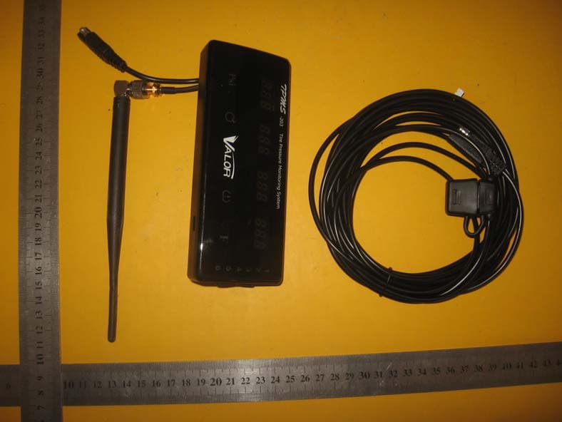
Y5DTPMS203-RD
Jan 12, 2011TPMS-RD
Equipment Class
CYY - Communications Receiver used w/Pt 15 Transmitter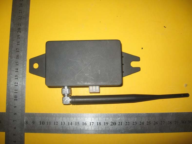
Y5DTPMS203-CANBUS
Jan 12, 2011TPMS-CANBUS
Equipment Class
DSR - Part 15 Remote Control/Security Device Transceiver