Y7O-CDD7428UBCAR AUDIO
Continental Automotive Technologies GmbH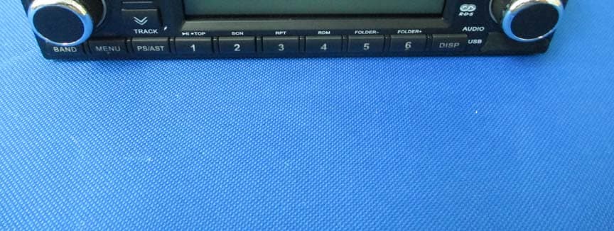
Click to zoom
Application Details
- Equipment Class
- DSS - Part 15 Spread Spectrum Transmitter
- Date of Grant
- Sep 30, 2014
- Application Purpose
- Original Equipment
- Date of Application
- Sep 30, 2014
- Equipment Note
- CAR AUDIO
- Frequency Range
- 2402.00000000 - 2480.00000000
- Country
- Germany
Documents & Files
Document Text
Text extracted from the exhibit documents filed with the FCC. Open a document above to read the original.
Users Manual
210mm 142.5mm P13 封底 封面 P2 9682CMB4491QB339A 127075006268 CMB4491QB339A, INSTRUCTION MANUAL 郑小虔 2014-9-13 宋 巍 70g书写纸 鲍静芳 胡知先 汪旺春 温志远 2014-9-13 2014-9-13 2014-9-13 2014-9-13 2014-9-13 空白 空白 共16P CDD7428UB-OR OWNER'S MANUAL CDD7428UB-OR 9682CMB4491QB339A.indd 12014-9-5 15:06:23 2 Safety InformationContents Safety Information........................................2 Contents.........................................................2 Panel Controls...............................................3 Operate guide ..............................................4 Sound setting ..............................................5 System Setting Item List..............................................6 USB MP3/WMA Overview.............................7 Bluetooth Operations.............................8 Electrical Connections................................10 Troubleshooting..........................................11 Specifications..............................................12 FCC Statement..............................................13 Precautions • Use only in a 24-volt DC negative- ground electrical system. • Disconnect the vehicle's negative battery terminal while mounting and connecting the unit. • When replacing the fuse, be sure to use one with an identical amperage rating. Using a fuse with a higher amperage rating may cause serious damage to the unit. • DO NOT attempt to disassemble the unit. Laser beams from the optical pickup are dangerous to the eyes. • Make sure that pins or other foreign objects do not get inside the unit , they may cause malfunctions, or create safety hazards such as electrical shock or laser beam exposure. • If you have parked the car for a long time in hot or cold weather, wait until the temperature in the car becomes normal before operating the unit. • Keep the volume at a level you can hear outside warning sounds (horns sirens, etc.). CD Notes • Playing a defective or dusty CD can cause dropouts in sound. • Hold CDs as illustrated. • Do not touch the unlabeled side. • Do not attach any seal, label or data protection sheet to either side of a disc. • Do not expose a CD to direct sunlight or excessive heat. • Wipe a dirty CD from the center outward with a cleaning cloth. • Never use solvents such as benzine or alcohol. • This unit cannot play 3-inch ( 8cm ) CDs. NEVER insert a 3-inch CD contained in the adapter or an irregularly shaped CD. The unit may not be able to eject it, resulting n a malfunction. • Disc can not have foreign body, the damage caused by the disc with foreign body do not belong to the warranty scope. Before Operation • Do not raise the volume level too much, as this will block outside sounds, making driving dangerous. Stop the car before performing any complicated operation. CAUTION • DO NOT open covers and do not repair yourself. Consult the dealer or an experienced technician for help. * In addition to ordinary CDs, this unit can playback CD - R or CD - RW, MP3. Note: The system just support the English and number display , not all kinds letters are compatible with th unit. CDD7428UB-OR 9682CMB4491QB339A.indd 22014-9-5 15:06:24 3 Panel Controls 1. -Disc eject 2 . -Rotate to adjust volume. -Radio: Mute -CD/MP3: Pause -Hold it to power off 3.- Band select 4.-1-6 preset -Automatically search and save station 5.-Channel 1/Play/Stop/Top 6.-Channel 2/SCN 7.-Channel 3/RPT 8.-Channel 4/RDM 9.-Channel 5/FOLDER- 10.-Channel 6/FOLDER+ 11. - Display paly time and clock in the CD state. - the LCD will display the ID3 TAG information recycle: file name/folder name/ID3 TAG/system time in the MP3 state. - Display PTY info and system time in the Radio state. 12.-Menu select 13.-USB connector 14.-Seek+/Select the next track 15.-Seek-/Select the previous track 16.-Disc slot 17.-SCR button Radio Disc(when disc is in) USB(when USB inserted) AUX IN 18.-Reset hole 19.-Press to select VOL/BAS/TRE/BAL/LOUD/FAD/ AF/TA/PTY, rotate VOL knob to adjust -RADIO: Rotate to adjust radio tune -CD /MP3: Rotate to select the previous/next track 20.1-6 preset: Press to tune in a preset station. Hold for more than 2 seconds to store a desired station. 21. Microphone CDD7428UB-OR 9682CMB4491QB339A.indd 32014-9-5 15:06:24 4 Operate Guide Disc Load / Eject Load : Insert the disc into the slot. Eject: Press to eject the disc. Band Mode Press the button to change bands: FM1 FM2 FM3 AM1 AM2 LW SRC Press the [SRC] button to switch between and select available sources, the mode as follows: TUNER->CD/MP3/USB->AUX ->DAB Auto Memory Store(Radio mode) Press the [PS/AST] button to scan the preset stations 1-6 for 10 seconds each. Hold the [PS/AST] button more than 2 seconds, the strongest available stations will be automatically saved in the memory of preset button 1-6 . Seek Mode Disc/USB playback: Press the / to select the next or previous track. Hold the / to enter fast forward or reverse back mode. EQ Loud Mode Press the [TUNE] Knob and rotate to select sound effect EQ OFFPOPROCK CLASSICJAZZCUSTOM Press the [TUNE] button and press / to select BAS/TRE, rotate the [TUNE] knob to adjust value. Clock Setting Long press the [DISP] button to set the time. On the non time display menu: Press the [TUNE] knob to enter the time setting state. The hours blinks on the screen, rotate the [TUNE] knob to set the hours and minutes, for adjusting is ok, press the [TUNE] knob to exit the clock setting. System Setting On the radio source hold the [DISP] to enter the system setup menu, press the / to select: TA TA RETUNAFREG CTDX/LOST/MONOCLOCK 12/24HBEEPSWRC SETLOGIC AREA SET, and rotate the [TUNE] to setting. BEEP setting: The beep tone feature allows the selection of an audible beep tone to be heard each time the menu is accessed. SWRC setting: Rotate the [TUNE] knob to select ON or OFF. DX/LO setting: Rotate the [TUNE] knob to select DX or LO. CT setting: Rotate the [TUNE] knob to select ON or OFF. REG setting: Rotate the [TUNE] knob to select ON or OFF. AF setting: Rotate the [TUNE] knob to select ON or OFF. TA…
Text truncated - open the document above for the full version.
ID Label/Location Info
温志远 2014-8-19 宋巍 汪旺春 127071007810 9682CMB4491QB339A CMB4491QB339A MODEL LABEL , 胡知先 陈 亮/郑小虔 2014-8-19 2014-8-19 2014-8-19 2014-8-19 A Compartment No. Pin Definition A4 A5 A6 A7 A8 B Compartment No. Pin Definition B1 B2 B3 B4 B5 B6 B7 B8 C Compartment No. Pin Definition MIC+ C1 MIC- C2 A3 C3 C6 C8 C5 C7 AUX-L AUX-R AUX-GND SWRC+ SWRC-GND A B C 1357 2468 1357 2468 1 4 7 10 13 1619 2 5 8 11 14 1720 3 6 9 12 15 18 M/N: CDD7428UB-OR PN.:127071007810 60mm FCC STATEMENT This device complies with Part 15 of the FCC Rules.Operation is subject to the following two conditions: (1) This device may not cause harmful interference. (2) This device must accept any interference received, including interference that may cause undesired operation. 10R-04 3070 FCC ID:Y7O-CDD7428UB Label
RF Exposure Info
东莞市东电检测技术有限公司 Dongguan Dongdian Testing Service Co.,Ltd Tel: 0769-22891499 http://www.dgddt.com IEIE Public Laboratory Page 1 of 1 RF Exposure evaluation According to 447498 D01 General RF Exposure Guidance v05 The 1-g and 10-g SAR test exclusion thresholds for 100 MHz to 6 GHz at test separation distances ≤ 50 mm are determined by: [(max. power of channel, including tune-up tolerance, mW)/(min. test separation distance, mm)] ·[√f(GHz)] ≤ 3.0 for 1-g SAR and ≤ 7.5 for 10-g extremity SAR, where: f(GHz) is the RF channel transmit frequency in GHz Power and distance are rounded to the nearest mW and mm before calculation The result is rounded to one decimal place for comparison Worse case is as below: [2402MHz, 2.45dBm (1.76mW) output power] (1.76/5) ·[√2.402(GHz)]= 0.546 <3.0 for 1-g SAR Then SAR evaluation is not required Jamy Yu 2014-09-22
Test Report
Dongguan Dongdian Testing Service Co., Ltd Report No:DDT-RE140650 Page 1 of 75 FCC CERTIFICATION TEST REPORT FOR Issued By: Dongguan Dongdian Testing Service Co., Ltd. Add: No. 17, Zongbu Road 2, Songshan Lake Sci&Tech, Industry Park, Dongguan City, Guangdong Province, China, 523808 Tel: +86-0769-22891499 Http://www.dgddt.com Applicant : Continental Automotive GmbH Address : Philipsstrasse 1, 35576 Wetzlar, Germany Equipment under Test : CAR AUDIO Model No : CDD7428UB-OR Trade Mark : Continental FCC ID : Y7O-CDD7428UB Manufacturer : Huizhou Foryou General Electronics Co., Ltd. Address : North Shangxia Road, Dongjiang Hi-tech Industry Park, Huizhou, Guangdong Province, 516005,P R China Report No: DDT-RE140650 Issued Date: Sept. 12, 2014 Dongguan Dongdian Testing Service Co., Ltd Report No:DDT-RE140650 Page 2 of 75 TABLE OF CONTENTS Test report declares......................................................................................................................4 1. Summary of test results ............................................................................................................... 5 2. General test information .............................................................................................................. 6 2.1. Description of EUT ..................................................................................................................... 6 2.2. Assistant equipment used for test ................................................................................................ 6 2.3. Block diagram of EUT configuration for test ............................................................................. 6 2.4. Test environment conditions ....................................................................................................... 7 2.5. Test laboratory............................................................................................................................. 7 2.6. Measurement uncertainty ............................................................................................................ 7 3. Maximum Peak Output Power ....................................................................................................8 3.1. Test equipment ............................................................................................................................ 8 3.2. Block diagram of test setup ......................................................................................................... 8 3.3. Limits .......................................................................................................................................... 8 3.4. Test Procedure............................................................................................................................. 9 3.5. Test Result................................................................................................................................... 9 4. 20dB Bandwidth........................................................................................................................ 10 4.1. Test equipment .......................................................................................................................... 10 4.2. Block diagram of test setup ....................................................................................................... 10 4.3. Limits ........................................................................................................................................ 10 4.4. Test Procedure........................................................................................................................... 10 4.5. Test Result................................................................................................................................. 11 4.6. Original test data ....................................................................................................................... 11 5. Carrier Frequency Separation.................................................................................................... 15 5.1. Test equipment .......................................................................................................................... 15 5.2. Block diagram of test setup ....................................................................................................... 15 5.3. Limits ........................................................................................................................................ 15 5.4. Test Procedure........................................................................................................................... 15 5.5. Test Result................................................................................................................................. 15 5.6. Original test data ....................................................................................................................... 16 6. Number Of Hopping Channel ...................................................................................................17 6.1. Test equipment .......................................................................................................................... 17 6.2. Block diagram of test setup ....................................................................................................... 17 6.3. Limits ........................................................................................................................................ 17 6.4. Test Procedure........................................................................................................................... 17 6.5. Test Result................................................................................................................................. 17 6.6. Original test data ........................................................................................................…
Text truncated - open the document above for the full version.
Contact Information
Applicant
Thomas Heselberger
Test Firm
Dongguan Dongdian Testing Service Co.,LtdJamy Yu
[email protected]086-0769-22891499
Technical Specifications
| # | Rule Parts | Frequency Range | Power Output |
|---|---|---|---|
| 1 | 15C | 2.40 GHz - 2.48 GHz | 1.76 mW |
Other Applications from Continental Automotive Technologies GmbH

Y7O-TRD312UB-BU
Feb 01, 2021CAR RADIO
Equipment Class
DSS - Part 15 Spread Spectrum Transmitter
Y7O-CSP1321
Dec 24, 2020SPEAKER
Equipment Class
DSS - Part 15 Spread Spectrum Transmitter
Y7O-CDD7418UB
Sep 27, 2014CAR AUDIO
Equipment Class
DSS - Part 15 Spread Spectrum Transmitter
Y7O-TR7423UB
Sep 27, 2014CAR AUDIO
Equipment Class
DSS - Part 15 Spread Spectrum Transmitter
Y7O-TR7412UB
Sep 27, 2014CAR AUDIO
Equipment Class
DSS - Part 15 Spread Spectrum Transmitter