Y7O-TR7423UBCAR AUDIO
Continental Automotive Technologies GmbH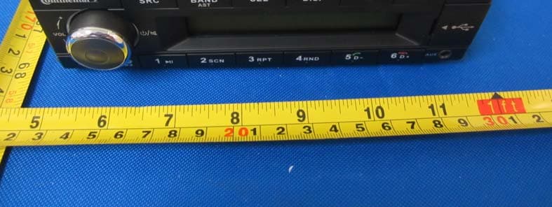
Click to zoom
Application Details
- Equipment Class
- DSS - Part 15 Spread Spectrum Transmitter
- Date of Grant
- Sep 27, 2014
- Application Purpose
- Original Equipment
- Date of Application
- Sep 27, 2014
- Equipment Note
- CAR AUDIO
- Frequency Range
- 2402.00000000 - 2480.00000000
- Country
- Germany
Documents & Files
Document Text
Text extracted from the exhibit documents filed with the FCC. Open a document above to read the original.
Users Manual
TR7423UB-OR OWNER'S MANUAL 1 Safety InformationThank you for purchasing this product, please read the manual carefully before operating, and reserve it for future reference.PRECAUTIONS• Only in a 24-volt DC negative-ground electrical system. • Disconnect the vehicle's negative battery terminal while mounting and connecting the unit. • When replacing the fuse, be sure to use one with an identical amperage rating. Using a fuse with a higher amperage rating may cause serious damage to the unit. • Make sure that pins or other foreign objects do not get inside the unit, they may cause malfunctions, or create safety hazards such as electrical shock. • If you have parked the car for a long time in hot or cold weather, wait until the temperature in the car becomes normal before operating the unit. • Keep the volume at a level at which you can hear outside warning sounds (horns sirens, etc.). CAUTION• DO NOT open covers and do not repair by yourself. Ask the dealer or an experienced technician for help. BEFORE OPERATION• Do not raise the volume level too much, as this will block outside sounds, making driving dangerous. • Stop the car before performing any complicated operation. GeneralPower supply: 24V DC (18V-32V) Maximum power output: 4X15W Suitable speaker impedance: 4ohmFuse spec: 10A Weight: 0.9kg Dimensions (WxDxH): 188x131x58.5mm Note: 1 According to models with different wiring harness to connect the definition of the specific content, please refer to the model label.2 Specifications and the design are subject to change without notice due to improvements in technology. Specifications Contents Frequency Table Safety Information ..................... ... ...............1 Specifications ............................................... 1 Panel Controls ..............................................2 Button Tips ....................................................3 Bluetooth Functions.......................................4USB function Summarization .........................4 Electrical connectons.................................5Troubleshooting ............................................6 2 Panel Controls (1). - Microphone(2). - Power on/off, - Mute, when on,hold it more than 2 seconds to power off. - Rotate the VOL knob to adjust volume. (3). - Source Radio, USB (when USB inserted), AUX IN, A2DP, Hold it more than 2 seconds to select PTY mode.(4). - Band switch: FM1 -> FM2 -> FM3 -> MW1 -> MW2-> LW - Hold it Automatically search station and store the signal strongly station to 1-6 Preset. (5). - P ress SEL and rotate VOL knob to select EQ preset mode: EQ OFF-POP-CLASSIC-ROCK-JAZZ - Press to enter,when selecting the PTY mode, - Press SEL and rotate VOL knob to ajust the time,when on the CLOCK mode. (6). - Display system clock - Hold it to setting clock - Radio mode: display PTY info/system clock/ current channel , - MP3 mode: Turn and turn about folder name/file name/ ID3 TAG/Clock .(7). - Radio mode - Auto search the station from high to low - MP3 mode Select the previous track (8). - Radio mode Auto search the station from low to high - MP3 mode Select the next track(9). - USB slot(10). - MP3 folder ahead/Hang up(11). - MP3 folder back/Contact mode/ Dial/Call transfer(12). - MP3 random play(13). - MP3 repeat play(14). - Program intro play(10 sec.)(15). - Play/pause(10-15). -1-6 radio preset Press to tune in a preset station. Hold for more than 2 seconds to store current station. 3 TA RETURN:On the FM mode ,set the TA time space Info of auto search with RDS.Setting for “LONG”, Auto search the TA time space for 180 sec,Setting for “SHORT”, auto search the TA time space for 45 sec.Region settingto select AMERICAN,EUROPE,ASIA,JAPAN.Press [SEL] button,and then press the [/ ]button to choose EQ/BAS/TRE/BAL/FAD/ LOUD function,rotate the konb to adjust . TuneRadio seek automatically Press the / button auto search the station from high to low or from low to high. Radio tune by step Hold it more than 2 second ,switch to the manual mode,press the button step search the station from high to low or from low to high. Manual Memory StoreAt FM1/FM2/FM3/MW1/MW2/LW mode, press and hold button 1-6 to store current station in memory. You can store 36 stations in total. (18 FM/ 18 AM) Button TipsMP3 PlaybackTrack skip Press the / button to go to the previous or next track.Hold it to enter fast forward or reverse back mode.MP3 track fast searchPress the [5D-]/[6D+]button to select MP3 folder back/ahead Set ClockRadio mode:press[DISP]button, T urn and turn display PTY/ Clock /current channel MP3 playback mode:press[DISP]button,Turn and turn about folder name/file name/ID3 TAG/Clock Then press [DISP]button more than 2 seconds, ‘Clock‘ displayed,press [SEL] button, rotate the[VOL]knob and press [ / ]button to set, press [SEL] to confirm. System settingOn the non time display menu:Hold it [DISP] and press [ / ]button to enter the system setup menu, . CLOCK TA TA RETURN AF REG CT DX/LO ST/MONO AUTO ANS AUTO CON F 12H/24H MIC SEL REGION SWRC (ON/OFF) LOGIC(ON/ OFF) SCROLL(ON/OFF) Wait for 1s and rotate the knob to set the system.TA setting :Rotate [VOL] knob to set ON/OFF. RDS Press the [DISP] button to set AF/TA/REG ,rotate the[VOL]knob to open or close AF/TA function.Hold the [SRC]button to PTY function ,rotate the [VOL]knob,display NEWS and POP program type.When display NEWS ,rotate the konb to select opposite presetNEWS-AFFAIRS-INFO-SPORT-EDUCATE-DRAMA-CULTURE-SCIENCE-VARIED-POP M-ROCK M-EASY M-LIGHT M-CLASSICS M-OTHER M-WEATHER -FINANCE-CHILDREN-SOCIAL -RELIGION-PHONE IN-TRAVEL-LEISURE-JAZZ-COUNTRY-NATION M-OLDIES-FOLK M-DOCUMENT-TEST-ALARMLogic ON/Logic OFFLogic ON to limit the use of the set to one hourwhen the car ignition is switched off.LogicOFFto prevent the set from turning on,whenthe car ignition is switched off. 4 Loading/Take out USB equipment1. Insert a USB device into the connector and the unit will begin to play automatically.2. To stop playback of USB device, push the SRC button to non USB mode and…
Text truncated - open the document above for the full version.
Cover Letter(s)
(Please print this form on your headed company notepaper) DATE : September 18. 2014 Nemko Canada Inc 303 River Road Ottawa, Ontario, Canada K1V 1H2 Attn: Director of Certification Authority to Act as Agent On our behalf, I appoint below company and person: Name Jamy Yu Position Manager Company Name Dongguan Dongdian Testing Service Co.,Ltd. Address 17, Zongbu Road 2, Songshan Lake Sci&Tech, Industry Park, Dongguan City, Guangdong Province, China, 523808 Tel / Fax Tel: +86-0769-22891499 fax:+86-0769-22895596 E-Mail [email protected] to act as our agent in the preparation of this application for equipment certification. I certify that submitted documents properly describe the device or system for which equipment certification is sought. I also certify that each unit manufactured, imported or marketed, as defined in the Federal Communications Commission’s regulations will have affixed to it a label identical to that submitted for approval with this application. For instances where our authorized agent signs the application for certification on our behalf, I acknowledge that all responsibility for complying with the terms and conditions for certification, as specified by Nemko Canada Inc, still resides with: Applicant name Continental Automotive GmbH Address Philipsstrasse 1, 35576 Wetzlar, Germany Yours sincerely, Signatory Name Marc Goldbach Position Engineer Company Name Continental Automotive GmbH Address Philipsstrasse 1, 35576 Wetzlar, Germany Tel / Fax +49-6441-370 E-Mail [email protected]
Cover Letter(s)
Continental Automotive GmbH DATE : September 18. 2014 Equipment Autorisation Division Federal Communications Commission 7435 Oakland Mills Road Columbia, MD 21046 FCC ID: Y7O-TR7423UB Product Name: CAR AUDIO Request for Confidentiality Pursuant to Sections 0.457 and 0.459 of the commissions rules, we hereby request that the following documents be held confidential: Exhibit Type Description ☒ Schematics All circuitry of devices and component values ☒ Block Diagrams Details of device showing the frequency of all oscillators ☒ Operational Description Description of the circuit functions These materials contain trade secrets and proprietary information and are not customarily released to the public. The public disclosure of this information might be harmful to the company and provide unjustified benefits to our competitors. Yours sincerely, Signatory Name Marc Goldbach Position Engineer Company Name Continental Automotive GmbH Address Philipsstrasse 1, 35576 Wetzlar, Germany Tel / Fax +49-6441-370 E-Mail [email protected]
RF Exposure Info
东莞市东电检测技术有限公司 Dongguan Dongdian Testing Service Co.,Ltd Tel: 0769-22891499 http://www.dgddt.com IEIE Public Laboratory Page 1 of 1 RF Exposure evaluation According to 447498 D01 General RF Exposure Guidance v05 The 1-g and 10-g SAR test exclusion thresholds for 100 MHz to 6 GHz at test separation distances ≤ 50 mm are determined by: [(max. power of channel, including tune-up tolerance, mW)/(min. test separation distance, mm)] ·[√f(GHz)] ≤ 3.0 for 1-g SAR and ≤ 7.5 for 10-g extremity SAR, where: f(GHz) is the RF channel transmit frequency in GHz Power and distance are rounded to the nearest mW and mm before calculation The result is rounded to one decimal place for comparison Worse case is as below: [2402MHz, 2.43dBm (1.75mW) output power] (1.75/5) ·[√2.402(GHz)]= 0.542<3.0 for 1-g SAR Then SAR evaluation is not required Jamy Yu 2014-09-22
Test Report
Dongguan Dongdian Testing Service Co., Ltd Report No:DDT-RE140656 Page 1 of 73 FCC CERTIFICATION TEST REPORT FOR Issued By: Dongguan Dongdian Testing Service Co., Ltd. Add: No. 17, Zongbu Road 2, Songshan Lake Sci&Tech, Industry Park, Dongguan City, Guangdong Province, China, 523808 Tel: +86-0769-22891499 Http://www.dgddt.com Applicant : Continental Automotive GmbH Address : Philipsstrasse 1, 35576 Wetzlar, Germany Equipment under Test : CAR AUDIO Model No : TR7423UB-OR Trade Mark : Continental FCC ID : Y7O-TR7423UB Manufacturer : Huizhou Foryou General Electronics Co., Ltd. Address : North Shangxia Road, Dongjiang Hi-tech Industry Park, Huizhou, Guangdong Province, 516005,P R China Report No: DDT-RE140656 Issued Date: Sept. 12, 2014 Dongguan Dongdian Testing Service Co., Ltd Report No:DDT-RE140656 Page 2 of 73 TABLE OF CONTENTS Test report declares......................................................................................................................4 1. Summary of test results ............................................................................................................... 5 2. General test information .............................................................................................................. 6 2.1. Description of EUT ..................................................................................................................... 6 2.2. Assistant equipment used for test ................................................................................................ 6 2.3. Block diagram of EUT configuration for test ............................................................................. 6 2.4. Test environment conditions ....................................................................................................... 7 2.5. Test laboratory............................................................................................................................. 7 2.6. Measurement uncertainty ............................................................................................................ 7 3. Maximum Peak Output Power ....................................................................................................8 3.1. Test equipment ............................................................................................................................ 8 3.2. Block diagram of test setup ......................................................................................................... 8 3.3. Limits .......................................................................................................................................... 8 3.4. Test Procedure............................................................................................................................. 9 3.5. Test Result................................................................................................................................... 9 4. 20dB Bandwidth........................................................................................................................ 10 4.1. Test equipment .......................................................................................................................... 10 4.2. Block diagram of test setup ....................................................................................................... 10 4.3. Limits ........................................................................................................................................ 10 4.4. Test Procedure........................................................................................................................... 10 4.5. Test Result................................................................................................................................. 11 4.6. Original test data ....................................................................................................................... 11 5. Carrier Frequency Separation.................................................................................................... 15 5.1. Test equipment .......................................................................................................................... 15 5.2. Block diagram of test setup ....................................................................................................... 15 5.3. Limits ........................................................................................................................................ 15 5.4. Test Procedure........................................................................................................................... 15 5.5. Test Result................................................................................................................................. 15 5.6. Original test data ....................................................................................................................... 16 6. Number Of Hopping Channel ...................................................................................................17 6.1. Test equipment .......................................................................................................................... 17 6.2. Block diagram of test setup ....................................................................................................... 17 6.3. Limits ........................................................................................................................................ 17 6.4. Test Procedure........................................................................................................................... 17 6.5. Test Result................................................................................................................................. 17 6.6. Original test data ..........................................................................................................…
Text truncated - open the document above for the full version.
Contact Information
Applicant
Thomas Heselberger
Test Firm
Dongguan Dongdian Testing Service Co.,LtdJamy Yu
[email protected]086-0769-22891499
Technical Specifications
| # | Rule Parts | Frequency Range | Power Output |
|---|---|---|---|
| 1 | 15C | 2.40 GHz - 2.48 GHz | 1.75 mW |
Other Applications from Continental Automotive Technologies GmbH

Y7O-TRD312UB-BU
Feb 01, 2021CAR RADIO
Equipment Class
DSS - Part 15 Spread Spectrum Transmitter
Y7O-CSP1321
Dec 24, 2020SPEAKER
Equipment Class
DSS - Part 15 Spread Spectrum Transmitter
Y7O-CDD7428UB
Sep 30, 2014CAR AUDIO
Equipment Class
DSS - Part 15 Spread Spectrum Transmitter
Y7O-CDD7418UB
Sep 27, 2014CAR AUDIO
Equipment Class
DSS - Part 15 Spread Spectrum Transmitter
Y7O-TR7412UB
Sep 27, 2014CAR AUDIO
Equipment Class
DSS - Part 15 Spread Spectrum Transmitter