Y7O-CSP1321SPEAKER
Continental Automotive Technologies GmbH
Click to zoom
Application Details
- Equipment Class
- DSS - Part 15 Spread Spectrum Transmitter
- Date of Grant
- Dec 24, 2020
- Application Purpose
- Original Equipment
- Date of Application
- Dec 24, 2020
- Equipment Note
- SPEAKER
- Frequency Range
- 2402.00000000 - 2480.00000000
- Country
- Germany
Documents & Files
Document Text
Text extracted from the exhibit documents filed with the FCC. Open a document above to read the original.
Users Manual
VDO IZI Speaker OWNER’S MANUAL Public December 25, 2020 1 , © Legal entity | VDO – A Trademark of the Continental Co rporation 2 Safety Information Contents Safety Information ......................................... 2 Thank you for purchasing this product, Before operation Panel Controls ............................................... 3 General Operation ....................................... .. 4 Volume and Sound ........................................ 4 USB/MP3 ........................................................ 7 Bluetooth functions 8 please read the manual carefully before operating, and reserve it for future reference. Before operation Do not raise the volume level too high. Keep the volume at a level at which you can hear outside warning sounds (horns sirens, Precaution Bluetooth functions ......................................... 8 System Settings Items List ..............................11 Electrical connections....................................14 Troubleshooting ............................................16 S p ecifications................................................17 etc.). Stop the vehicle before performing any complicated operations. Caution Use only in a 12-volt DC negative- ground electrical system Disconnect the vehicle's negative battery terminal while mounting and connecting the unit p Caution Do not open the cover and do not repair by yourself. Ask your authorised dealer for help. the unit . Use an additional fuse on the 12-volt DC Using a fuse with a higher amperage rating may cause serious damage to the unit. Declaration of Conformity:Continental Aftermarket & Services GmbH declares the radio has been so constructed that it complies with basic requirements and Note:1 Specifications and the design are subject tochange without notice due to improvements intechnology. Make sure that pins or obstacles do not get inside the unit, they may cause malfunctions, or create safety hazards such as electrical shock. other relevant regulations of the European Union directives 2014/53/EU. You can find the declaration of conformity on our website www.conti nental-automotive,com Public Panel Controls 3 (1) Power button ‐On/Off (2s) / Source (<1s) 4 (2) USB MP3/Bluetooth Play/Pause (<1s) Mono/Stereo mode (3s) (3) Previous Track 2 3 6 (4) Next Track(5) Volume ‐button(6) Volume + button(7) H d f lli b 6 12 9 10 (7) H an d s‐ f ree ca lli ng b utton (8) BASS button(9) Blue LED / Bluetooth mode 12 11 5 1 (10) Green LED / USB mode(11) Orange LED / Auxiliary mode(12) USB slot 8 1 7 Public 4 General Operation Sl tS PON/OFF Volume and Sound S e l ec t S ource Short push the [ON/OFF] button to switch between and select available sources: Bluetooth USB AUX V olume To adjust the Volume push the [-] or [+] buttons, or the volume on your smartphone in Bluetooth mode only.Manual Bass Adjustment P ower ON/OFF To Switch on the Radio push 2s the Power ON/OFF button.To switch off the Radio push 2s the Power ON/OFF button. Manual Bass Adjustment Push the [BASS] button select the bass level:+ 2dB 4dB 6dB 0dB 2dB 4dB 6dB... Stereo / MonoThe Mono mode is the default mode if you want Default to enter the Bluetooth playback mode, when there is a AUX/USB insert, directly into the AUX/USBplayback mode, when the AUX/USB cancel playback, automatically return to play Bluetooth. The Mono mode is the default mode , if you want to connect an additional speaker, please press the Volume + and Volume – buttons during 3 seconds to change to the stereo mode.To come back to the mono mode you need to p ress a g ain the Volume + and Volume – buttons Note: If no sound played, the speaker will switch off automatically after 10 minutes, pgduring 3 seconds. Public 7 USB/MP3 NoteonMP3 USBNotes ( f (fl h MP3 Playback/PauseTo pause and resume MP3 Playback push button •MP3 is short for MPEG Audio Layer 3 and referstoanaudiocompressiontechnologystandard.•ThisproductallowsplaybackofMP3files.•The unit can not read an MP3 file that has a file ( FAT12, FAT16, FAT32, USB f unctions (fl as h memory type)MP3musicplay. USBflashmemory2in1support Themaximumnumberoffiles:32G EXFAT ) format su pp orted. [>||]. Next/Previous MP3 Track.To select the next/previous track push the [|<</>>|] button. extensionotherthan".mp3".•If you play a non‐MP3 file that has the “.mp3"extension,youmayhearsomenoise.•TheunitmaynotplaytracksintheorderofTrack b )pp USB1.1support,USB2.0support (For2.0,speedperformanceisasUSB1.1) NotallUSBdevicesarecompatiblewiththeunit. USBconnectorissu pp ortmaximumwork p ower Fast forward/fast rewind.To fast forward/fast rewind the current track push the [|<</>>|] button longer than 2 sec. Loading/ Removal of USB DeviceI USB di i h USB l “R di ” i num b ers. •Supportmusicformats:MP3,LayerI,II,III,WAV(PCM,IMA‐ADPCM)MP3 acceptance frequency: 44100KHz, VBR, CBR pp p with1000mA. I nsert a USB d ev i ce i nto t h e USB ‐s l ot “R ea di ng ” i s shown on the Display. MP3 Playback will startimmediateafterwards.BeforeremovingtheUSBDeviceswitchtoanotherSourcebypushingthe[ON/OFF]button. Public 8 Bluetooth functions The Bluetooth allows you to utilize your vehicle’s built-in audio system for wireless mobile p hone or music hands free Hands free OperationsPairing1.Turn on Bluetooth function of your mobile p hone. p communication. Some Bluetooth mobile phones have the audio features, and some portable audio players support Bluetooth feature. This system can play audio data stored in a Bluetooth audio device. The vehicle stereo with Bluetooth will be able to p2.Enter mobile phone’s Bluetooth setup menu.3.Search for new Bluetooth devices. (Continental Bluetooth)4.Select Bluetooth devices from the pairing list on the mobile phone.5.Pairing code: no code/ automatic pairing retrieve incoming calls, outgoing call and listen to music. Notes:• Do not leave the microphone on Bluetooth hands free in the places with wind passing such as air outlet of the air diti t Thi process6.After pairing successfully,…
Text truncated - open the document above for the full version.
Attestation Statements
Continental Automotive GmbH Date: 2020-11-20 To: Federal Communications Commission 7435 Oakland Mills Road Columbia, MD FCC ID: Y7O-CSP1321 To Whom It May Concern: This letter is to ascertain that Continental Automotive GmbH EUT : SPEAKER Model Name : CSP1321-BL, CSP1321-WH We will apply for FCC SDOC. If you have any question or concerns, pls. contact us. Sincerely, Client’s signature : Client’s name / title : Marc Goldbach / Dipl. Ing. Contact information / address: Continental Automotive GmbH /Philipsstrasse 1, Wetzlar,Germany 35576
Cover Letter(s)
Rev 11/20/07 (Continental Automotive GmbH) Federal Communications Commission Authorization and Evaluation Division Confidentiality Request regarding application for certification of FCC ID: Y7O-CSP1321 Pursuant to Sections 0.457 and 0.459 of the Commission’s Rules, we hereby request confidential treatment of information accompanying this application as outlined below: Exhibit Type File Name Block Diagram, Schematics, Operational Description Block Diagram .pdf, Schematics .pdf , Operation Description .pdf The above materials contain trade secrets and proprietary information not customarily released to the public. The public disclosure of these materials may be harmful to the applicant and provide unjustified benefits to its competitors. The applicant understands that pursuant to Section 0.457 of the Rules, disclosure of this application and all accompanying documentation will not be made before the date of the Grant for this application. Pursuant to DA04-1705 June 15, 2004 of the Commission’s public notice, we also request temporary confidential treatment of information accompanying this application as outlined below: Short-term confidentiality requested: 180 days Exhibit Type File Name Internal Photos, Test Setup Photos, Manual Internal Photos.pdf, Test Setup Photos.pdf, User Manual .pdf Sincerely, Marc Goldbach / Dipl. Ing. Continental Automotive GmbH
Cover Letter(s)
Difference Statement Models CSP1321-BL, CSP1321-WH are the same except the color. December 19, 2020 Marc Goldbach / Dipl. Ing. Continental Automotive GmbH
Cover Letter(s)
Z:\2020\Ultimate(好德美)\EN200923012W(ES200923032W)\2.Technical Document\Timco\POA.docx (Continental Automotive GmbH) Federal Communications Commission Authorization and Evaluation Division 1435 Oakland Mills Road Columbia, MD 21046 Date: November 20, 2020 SUBJECT: FCC Application for FCC ID: Y7O-CSP1321 To Whom It May Concern: We, the undersigned, hereby authorize Tony Wei at EMTEK(NINGBO) CO., LTD. on our behalf, to apply to the Federal Communications Commission on our equipment. Any and all acts carried out by EMTEK(NINGBO) CO., LTD. on our behalf shall have the same effect as acts of our own. This is to advise that we are in full compliance with the Anti- Drug Abuse Act. We, the applicant, are not subject to a denial of federal benefits pursuant to Section 5301 of the Anti-Drug Act of 1988, 21 USC853a, and no party to the application is subject to a denial of federal benefits pursuant to that section. Regards, Marc Goldbach / Dipl. Ing. Continental Automotive GmbH
External Photos
External photos: ---The End---
ID Label/Location Info
Label: Location:
Internal Photos
Internal photos: Antenna ---The End---
RF Exposure Info
FCC ID: Y7O-CSP1321 RF EXPOSURE EVALUATION According to FCC 1.1310: The criteria listed in the following table shall be used to evaluate the environment impact of human exposure to radio frequency(RF) Radiation as specified in §1.1307(b) Limits for Maximum Permissible Exposure (MPE) Frequency Range(MHz) Electric Field Strength(V/m) Magnetic Field Strength(A/m) Power Density(mW/cm 2 ) Average Time (A) Limits for Occupational/Control Exposures 300-1500 -- -- F/300 6 1500-100000 -- -- 5 6 (B) Limits for General Population/Uncontrol Exposures 300-1500 -- -- F/1500 6 1500-100000 -- -- 1 30 11.1 Friis transmission formula: Pd= (Pout*G)\ (4*pi*R 2 ) Where Pd= Power density in mW/cm 2 Pout=output power to antenna in mW G= Numeric gain of the antenna relative to isotropic antenna Pi=3.1416 R= distance between observation point and center of the radiator in cm Pd the limit of MPE,1mW/cm 2 . If we know the maximum gain of the antenna and total power input to the antenna, through the calculation, we will know the distance where the MPE limit is reached. mW = 10^( dBm/10) 11.2 Measurement Result Operation Frequency: 2402MHz-2480MHz; Antenna gain: 0.0 dBi; R=20cm BR/EDR Channel Freq. (MHz) modulation Measured power (dBm) Tune-up power (dBm) Max tune-up power (dBm) Antenna Gain Numeric Evaluation result (mW/cm2) Power density Limits (mW/cm2 ) 2402 GFSK -4.367 -6 to -4 -4 1.0 0.000079201 1 2440 -3.734 -5 to -3 -3 1.0 0.000099708 1 2480 -3.469 -5 to -3 -3 1.0 0.000099708 1 2402 pi/4- DQPSK -3.728 -5 to -3 -3 1.0 0.000099708 1 2440 -3.929 -5 to -3 -3 1.0 0.000099708 1 2480 -4.675 -6 to -4 -4 1.0 0.000079201 1 2402 8DPSK -4.365 -6 to -4 -4 1.0 0.000079201 1 2440 -3.764 -5 to -3 -3 1.0 0.000099708 1 2480 -3.308 -5 to -3 -3 1.0 0.000099708 1 *** End of Report ***
Test Report
Report No. ES200923032W Page 1 of 59 Ver.1.0 TEST REPORT $二维码$ Product Name : SPEAKER Model Number : CSP1321-BL, CSP1321-WH FCC ID : Y7O-CSP1321 Prepared for : Continental Automotive GmbH Address : Philipsstrasse 1, Wetzlar,Germany 35576 Prepared by : EMTEK (SHENZHEN) CO., LTD. Address : Building 69, Majialong Industry Zone, Nanshan District, Shenzhen, Guangdong, China Tel: (0755) 26954280 Fax: (0755) 26954282 Report Number : ES200923032W Date(s) of Tests : September 23, 2020 to November 19, 2020 Date of issue : November 20, 2020 Report No. ES200923032W Page 2 of 59 Ver.1.0 Table of Contents 1 TEST RESULT CERTIFICATION ............................................................................................................ 3 2 EUT TECHNICAL DESCRIPTION .......................................................................................................... 4 3 SUMMARY OF TEST RESULT ............................................................................................................... 5 4 TEST METHODOLOGY .......................................................................................................................... 6 4.1 GENERAL DESCRIPTION OF APPLIED STANDARDS ....................................................................... 6 4.2 MEASUREMENT EQUIPMENT USED .................................................................................................. 6 4.3 DESCRIPTION OF TEST MODES ........................................................................................................ 7 5 FACILITIES AND ACCREDITATIONS ................................................................................................... 8 5.1 FACILITIES ............................................................................................................................................ 8 5.2 LABORATORY ACCREDITATIONS AND LISTINGS ............................................................................. 8 6 TEST SYSTEM UNCERTAINTY ............................................................................................................. 8 7 SETUP OF EQUIPMENT UNDER TEST ................................................................................................. 9 7.1 RADIO FREQUENCY TEST SETUP 1 .................................................................................................. 9 7.2 RADIO FREQUENCY TEST SETUP 2 .................................................................................................. 9 7.3 CONDUCTED EMISSION TEST SETUP ............................................................................................ 10 7.4 SUPPORT EQUIPMENT ..................................................................................................................... 11 8 FREQUENCY HOPPING SYSTEM REQUIREMENTS ......................................................................... 12 8.1 STANDARD APPLICABLE .......................................................................................................................... 12 8.2 EUT PSEUDORANDOM FREQUENCY HOPPING SEQUENCE ........................................................................ 12 8.3 EQUAL HOPPING FREQUENCY USE ......................................................................................................... 13 8.4 FREQUENCY HOPPING SYSTEM .............................................................................................................. 13 9 TEST REQUIREMENTS ........................................................................................................................ 14 9.1 20DB BANDWIDTH ............................................................................................................................. 14 9.2 CARRIER FREQUENCY SEPARATION ............................................................................................. 20 9.3 NUMBER OF HOPPING FREQUENCIES ........................................................................................... 26 9.4 AVERAGE TIME OF OCCUPANCY (DWELL TIME) ............................................................................ 28 9.5 MAXIMUM PEAK CONDUCTED OUTPUT POWER ........................................................................... 31 9.6 CONDUCTED SUPRIOUS EMISSION ............................................................................................... 37 9.7 RADIATED SPURIOUS EMISSION ..................................................................................................... 44 9.8 CONDUCTED EMISSION TEST ......................................................................................................... 57 9.9 ANTENNA APPLICATION ................................................................................................................... 58 Report No. ES200923032W Page 3 of 59 Ver.1.0 1 TEST RESULT CERTIFICATION Applicant : Continental Automotive GmbH Address : Philipsstrasse 1, Wetzlar,Germany 35576 Manufacturer : Ningbo Ultimate Acoustics Co.,Ltd. Address : 126#, Huiyuan Road, Hi-Tech Industrial Park, Fenghua,Ningbo, Zhejiang, China EUT : SPEAKER Model Name : CSP1321-BL, CSP1321-WH Trademark : Continental Measurement Procedure Used: APPLICABLE STANDARDS STANDARD TEST RESULT FCC 47 CFR Part 2 2018, Subpart J FCC 47 CFR Part 15 2018, Subpart C PASS The above equipment was tested by EMTEK(SHENZHEN) CO., LTD.The test data, data evaluation, test procedures, and equipment configurations shown in this report were made in accordance with the procedures given in ANSI C63.10 (2013) and the energy emitted by the sample EUT tested as described in this report is in compliance with the requirements of FCC Rules Part 2 and Part 15.247. The test results of this report relate only to the tested sample identified in this report. Date of Test : September 23, 2020 to November 19, 2020 Prepared by : Sewen Guo /Editor Reviewer : Joe Xia/Editor Approve & Authorized Signer : Lisa Wang/Manager Report No. ES200923032W Page 4 of 59 Ver.1.0 2 EUT TECHNICAL…
Text truncated - open the document above for the full version.
Test Setup Photos
Radiated ---The End---
Contact Information
Applicant
Thomas Heselberger
Test Firm
EMTEK (Shenzhen) Co., Ltd.Lisa Wang
[email protected]86 755 26954280
Technical Specifications
| # | Rule Parts | Frequency Range | Power Output |
|---|---|---|---|
| 1 | 15C | 2.40 GHz - 2.48 GHz | 500.00 µW |
Other Applications from Continental Automotive Technologies GmbH

Y7O-TRD312UB-BU
Feb 01, 2021CAR RADIO
Equipment Class
DSS - Part 15 Spread Spectrum Transmitter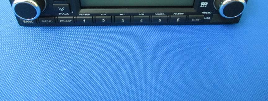
Y7O-CDD7428UB
Sep 30, 2014CAR AUDIO
Equipment Class
DSS - Part 15 Spread Spectrum Transmitter
Y7O-CDD7418UB
Sep 27, 2014CAR AUDIO
Equipment Class
DSS - Part 15 Spread Spectrum Transmitter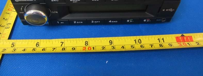
Y7O-TR7423UB
Sep 27, 2014CAR AUDIO
Equipment Class
DSS - Part 15 Spread Spectrum Transmitter
Y7O-TR7412UB
Sep 27, 2014CAR AUDIO
Equipment Class
DSS - Part 15 Spread Spectrum Transmitter