Y85HM-900MRF House Module
E.J. Ward, Inc.
Click to zoom
Application Details
- Equipment Class
- DXX - Part 15 Low Power Communication Device Transmitter
- Date of Grant
- Apr 07, 2011
- Application Purpose
- Original Equipment
- Date of Application
- Apr 07, 2011
- Equipment Note
- RF House Module
- Frequency Range
- 916.50000000 - 916.50000000
- Company
- E.J. Ward, Inc.
- Country
- United States
Documents & Files
Document Text
Text extracted from the exhibit documents filed with the FCC. Open a document above to read the original.
Users Manual
Page 1 of 5 Revision 2.11 Revised: 1/27/2011 RF Hose Module Installation OVERVIEW The E. J. Ward Hose Module provides wireless transfer of vehicle information, gathered by either the VIT or Canceiver mounted in the vehicle, to the Fuel Control Terminal (FCT). The RF Hose modules are automatically activated from fuel nozzle movement and orientation, thus making fuel authorization transparent to the user. In a typical transaction, the user drives up to the fuel pump, removes the nozzle from its holster and inserts it into the vehicle’s filler neck. This motion causes the hose module to poll for a VIT. When VIT/Canceiver data is received, the hose module transmits the data to the FCT for validation. Once VIT/Canceiver data is authorized, the dispenser is enabled and the user is allowed to fuel. The hose module continues to check for VIT/Canceiver presence during fueling. When the VIT/Canceiver is no longer present the pump is shut off. Compliance Statement: This device complies with Part 15 of the FCC Rules. Operation is subject to the following two conditions: (1) this device may not cause harmful interference, and (2) this device must accept any interference received, including interference that may cause undesired operation. INSTALLATION 1. Install the hose module on top of the hose nozzle using large UV-resistant nylon tie wraps (Figure 1.) Ideally, the module should be placed top of the nozzle, as far forward as possible, with the Ward logo on the spout-end of the nozzle. The module must not be placed too far forward on the handle so that it restricts normal insertion into a filler neck (Figure 2.) Alternately, the module may be side mounted on the nozzle (Figure 3.) Figure 1 Page 2 of 5 Revision 2.11 Revised: 1/27/2011 CAUTION: Installation of the module cannot modify or disturb the vinyl jacket on the hose nozzle. NOTICE: Healy 400 and 900 series nozzles are NOT permitted to have the hose modules mounted on the left side as it may interfere with the operation. Side mounting is only allowed on the right side as shown above. 2. The installer must also verify that the hose module does not interfere with dispenser or nozzle operation. After mounting the hose module place the nozzle back on the dispenser holster and verify the following conditions. a. The pump is not started simultaneously with lifting of the nozzle. b. Replacing the nozzle in the holster stops the pump. Additionally, the nozzle cannot be placed in the holster in a manner that leaves the pump energized. c. The nozzle can be locked with the use of an ordinary ¼ in. padlock. 3. To preserve battery life hose modules are “locked” before shipping from the E.J. Ward factory. To unlock the module, rub a strong magnet on the side marked by the “ MAGNETIC UNLOCK ” indication on the U.L label (Figure 4.) Figure 4 – Unlocking Module Figure 3 - Right Side Mount Figure 3 - Left Side Mount Figure 3 - Top Side Mount Page 3 of 5 Revision 2.11 Revised: 1/27/2011 PROGRAMMING 1. The installer must obtain unique identification numbers for the hose modules so its FCT will know which hose the VIT/Canceiver data came from. Hose module identification consists of three numbers: System Number, Terminal Number, and Hose Number. 2. Hose modules are programmed with the same Palmtop Programmer used to program VIT/Canceiver units. On the palmtop, exit the VIT/Canceiver Setup program using Menu 8. 3. At the DOS prompt, type HOSE and press <Enter>. 4. The Hose Module Setup Main Menu should appear (Figure 5.) 5. Press the <Space> bar and point the front edge (edge closest to the logo) of the hose module at the palmtop’s interface card (Figure 6.) After a short delay, the palmtop should beep and display the module’s current configuration. 6. If the module seems to not respond in Step 5, gently shake the module and retry Step 5. 7. Enter the correct System Number, Terminal Number, and Hose Number for the hose module. The ‘Prompt Type’ setting determines what type of data is requested from the VIT/Canceiver. If unsure of the correct setting, set ‘Prompt Type’ to ‘EEPROM’. 8. After entering all data, the bottom line of the screen should display ‘Update Hose Module or Exit’. If this line is not present, press <Enter> repeatedly until it is displayed. The left and right arrow keys will highlight the two different options. With ‘Update Hose Module’ highlighted, press <Enter> to send the new configuration data to the hose module. Again, point the front edge of the module at the palmtop’s interface card. After a short delay, the palmtop should beep, indicating a new configuration has been accepted. 9. Test the hose module with a good VIT/Canceiver or the VIT/Canceiver simulator function of the VIT/Canceiver palmtop program. 10. Exit the hose module program by pressing the escape key repeatedly. The hose module program will respond with “bye!” when it exits to DOS. Type VIT and press <Enter> to get back into the VIT/Canceiver program. 11. If problems are still experienced, review the back of the VIT Installation Guide V2.11 – Section 5.3 - Troubleshooting Hose Module Equipped Fuel Island, or call Ward Inc. at 210-824-7383 Page 4 of 5 Revision 2.11 Revised: 1/27/2011 Figure 5 - Hose Module Setup Program Figure 6 - Programming Hose Module Page 5 of 5 Revision 2.11 Revised: 1/27/2011 OPERATION The hose module is activated from nozzle movement and change in orientation. As the nozzle is inserted into the vehicle’s filler neck, the hose module will ‘prompt’ the VIT/Canceiver for its fueling data via electromagnetic link. Upon receiving the ‘prompt’, the VIT/Canceiver will respond with requested fueling data. Fueling data is analyzed by the module and relayed to the FCT via radio link. After analyzing and approving data from the module, the FCT will enable the appropriate dispenser. As long as the hose module is in the fueling orientation, any movement perceived by the module will cause the module to check if the VIT/Canceiver is still within range of the electromagnetic…
Text truncated - open the document above for the full version.
Cover Letter(s)
8801 Tradeway • San Antonio, Texas 78217 P 210.824.7383 • F 210.824.2031 • www.ejward.com Attention: Application Examiner Re: Request for confidentiality Applicant: EJ Ward FCC ID: Y85HM-900M To whom it may concern, Permanent Confidentiality Request is hereby submitted by E.J. Ward, Inc. to withhold permanently from public review certain portions of the application for equipment certification for the referenced FCC identifiers. This request for confidentiality is made pursuant to 47 CFR 0.457(d) and 0.459 of the FCC Rules. In particular, the following sections of the application are to be kept permanently confidential: Schematics Detailed Block diagrams Detailed Operational/Functional Description Parts list Short-term Confidentiality Request is hereby submitted by E.J. Ward, Inc. to withhold from public review for a period of 45 days from the date of the Grant of Equipment Authorization and prior to marketing, certain portions of the application for equipment certification for the referenced FCC identifiers. This request for confidentiality is made pursuant to 47 CFR 0.457(d) and 0.459 of the FCC Rules. In particular, the following sections of the application are to be kept confidential for a period of 45 days from the date of Authorization: Test setup photos External photos Internal photos User manual Rationale for request for confidentiality: EJ Ward has invested considerable time and materials in research and development to produce the referenced product. Disclosure of the permanently confidential portions of this application to competitors would not only give them significant competitive advantages in developing similar products, but would also disclose successful implementation of unpublished, leading edge technology developed by us. Disclosure of the short-term confidential portions of this application during the period of importation and/or distribution would reveal key aspects of proprietary technology to competitors and diminish the value of our investment in research and development. If you have questions or need further information, please contact the undersigned. Sincerely, Engineering Director E. J. Ward, Inc.
Test Report
This report is for the exclusive use of Intertek's Client and is provided pursuant to the agreement between Intertek and its Client. Intertek's responsibility and liability are limited to the terms and conditions of the agreement. Intertek assumes no liability to any party, other than to the Client in accordance with the agreement, for any loss, expense or damage occasioned by the use of this report. Only the Client is authorized to permit copying or distribution of this report and then only in its entirety. Any use of the Intertek name or one of its marks for the sale or advertisement of the tested material, product or service must first be approved in writing by Intertek. The observations and test results in this report are relevant only to the sample tested. This report by itself does not imply that the material, product, or service is or has ever been under an Intertek certification program. EMC Report for EJ Ward on the 916.5 MHz Hose Module Page 1 of 18 TEST REPORT Report Number: 100086439DAL-002 Project Number: G100086439 Report Issue Date: January 27, 2011 Product Designation: 916.5 MHz Hose Module Standards: FCC 15.249 – Operation within the bands 902-928 MHz, 2400- 2483.5MHz, 5725-5875, and 24.0-24.25 GHz. Tested by: Client: Intertek Testing Services NA, Inc. 1809 10 th St. Suite 400 Plano, TX 75074 - USA EJ Ward 8801 Tradeway St San Antonio, TX 78217 USA Report prepared by Report reviewed by William Cullen EMC Project Engineer Shawn McGuinness EMC Senior Project Engineer Intertek Report Number: 100086439DAL-002 Issued: 01/27/2011 EMC Report for EJ Ward on the 916.5 MHz Hose Module Page 2 of 18 TABLE OF CONTENTS 1Introduction and Conclusion .............................................................................................................. 3 2Test Summary ...................................................................................................................................... 3 3Description of Equipment Under Test................................................................................................ 4 4System setup including cable interconnection details, support equipment and simplified block diagram ........................................................................................................................................................ 5 5Overview of EUT (Low Power Transmitter) (FCC 15C –EUT Overview).......................................... 6 6Duty Cycle Determination (FCC 15A – 15.35(c))................................................................................ 7 7Radiated emissions (E-field) for low power intentional radiators. (Radiated Emissions LPD) .. 10 8Occupied Bandwidth (FCC Part 2.1049)...........................................................................................16 9Measurement Uncertainty ................................................................................................................. 17 10Revision History ............................................................................................................................. 18 Intertek Report Number: 100086439DAL-002 Issued: 01/27/2011 EMC Report for EJ Ward on the 916.5 MHz Hose ModulePage 3 of 18 1 Introduction and Conclusion The tests indicated in section 2.0 were performed on the product constructed as described in section 3.0. The remaining test sections are the verbatim text from the actual data sheets used during the investigation. These test sections include the test name, the specified test Method, a list of the actual Test Equipment Used, documentation Photos, Results and raw Data. No additions, deviations, or exclusions have been made from the standard(s) unless specifically noted. Based on the results of our investigation, we have concluded the product tested complies with the requirements of the standard(s) indicated. The results obtained in this test report pertain only to the item(s) tested. 2 Test Summary Section Test full name Test date Result 3 Description of Equipment Under Test --- --- 4 System setup including cable interconnection details, support equipment and simplified block diagram --- --- 5 Overview of EUT 01/06/11 Pass 6 Duty Cycle Determination 01/25/11 Pass 7 Radiated Emissions 01/06/11 Pass 8 Occupied Bandwidth 01/07/11 Pass Intertek Report Number: 100086439DAL-002 Issued: 01/27/2011 EMC Report for EJ Ward on the 916.5 MHz Hose ModulePage 4 of 18 3 Description of Equipment Under Test Equipment Under Test DescriptionManufacturerModel Number Serial Number 916.5 MHz Hose Module EJ Ward 916.5 MHz Hose Module Proto1 Receive Date: 12/20/10 Received Condition: Good Type: Production Description of Equipment Under Test The EUT is a transmitter that connects to a gas pump hose and transmits to a terminal when it is shaken to indicate which pump is being used when gassing up. Operating modes of the EUT: No.Descriptions of EUT Exercising 1 The transmitter was reprogrammed to transmit continuously after being shaken to allow the measurements to be made. The module is battery operated. Intertek Report Number: 100086439DAL-002 Issued: 01/27/2011 EMC Report for EJ Ward on the 916.5 MHz Hose ModulePage 5 of 18 4 System setup including cable interconnection details, support equipment and simplified block diagram 4.0 Method: 4.1 EUT Block Diagram: 4.2 Data: Qty DescriptionLengthShieldingFerrites None Support Equipment DescriptionManufacturerModel Number Serial Number none none none none Hose Module Intertek Report Number: 100086439DAL-002 Issued: 01/27/2011 EMC Report for EJ Ward on the 916.5 MHz Hose ModulePage 6 of 18 5 Overview of EUT (Low Power Transmitter) (FCC 15C –EUT Overview) 5.0 Method Complete the overview spreadsheet. Related Submittal(s) Grants: This report is for use with an application for certificate of a low power transmitter application. Data: EJ Ward Applicant Trade Name & Model No. 916.5 MHz Hose Module FCC Identifier TBD Frequency Range (MHz) 916.5 Antenna Type (15.203) Integral EJ Ward 8801 Trade…
Text truncated - open the document above for the full version.
Contact Information
Applicant
Paul Witt(Engineering Director)
Test Firm
Intertek Testing Services NA, Inc.Paul Coghill
Technical Specifications
| # | Rule Parts | Frequency Range | Power Output |
|---|---|---|---|
| 1 | 15C | 916.5 MHz - 916.5 MHz | - |
Other Applications from E.J. Ward, Inc.
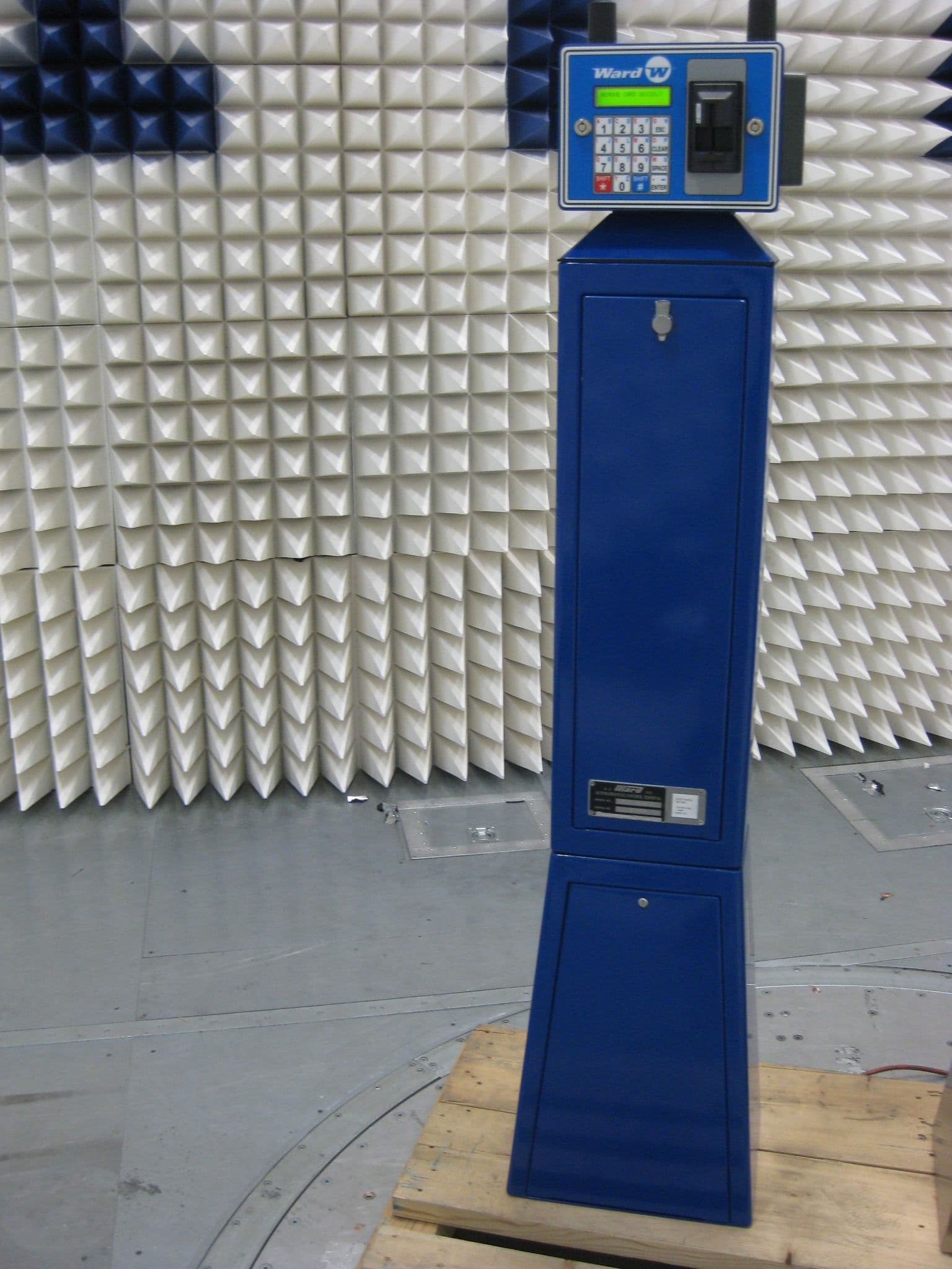
Y85FCT-900M
Jul 21, 2011RF fuel control terminal
Equipment Class
DXX - Part 15 Low Power Communication Device Transmitter
Y85FCT-2400M
May 08, 2011RF fuel control terminal
Equipment Class
DTS - Digital Transmission System
Y85HM-2400M
Apr 07, 2011RF House Module
Equipment Class
DXX - Part 15 Low Power Communication Device Transmitter