Y8YBTR20WIRELESS CYCLE COMPUTER TRANSMITTER
ECHOWELL ELECTRONIC CO., LTD.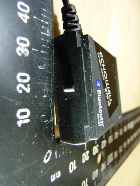
Click to zoom
Application Details
- Equipment Class
- DTS - Digital Transmission System
- Date of Grant
- Jul 31, 2013
- Application Purpose
- Original Equipment
- Date of Application
- Jul 31, 2013
- Equipment Note
- WIRELESS CYCLE COMPUTER TRANSMITTER
- Frequency Range
- 2402.00000000 - 2480.00000000
- Country
- Taiwan
Documents & Files
Document Text
Text extracted from the exhibit documents filed with the FCC. Open a document above to read the original.
Users Manual
SPEED TRANSMITTER AND MAGNET INSTALLATIONS 9 1. 10 2. Magnet center aligns to the sensing point . Gap<5mm 8 7 8 5 9 4 PADEL MAGNET 3 9 RPM Sensor Cap CR20 32 Speed Transmitter Battery Change Speed Transmitter For round spoke Für runde speichen Pour rayon classique. Voor ronde spaak Para ra dios re dondos Para ra io re dondo Per ra ggio tondo Kerek küllőhöz Do okrą głych szprych Pro kul atý p aprsek kol a ラウンド・スポーク の場合 Дл я кр углой спиц ы Pre o kr úhly lúč For rund eike Til runde eger Pyöre isiin pinnoihin För rund eker 라운드(원형의) 스포크용 For Round Spoke 1. The receiver will receive a stronger wireless signal if the speed Transmitter is more close to the receiver . A stronger sensing signal not only has better noise immunity, but also increases the speed Transmitter batt ery’s operating life. . 3. Adjust the sensor to let the gap between the magnet and the sensing point is about 5mm. 1. Der Empfänger empfängt ein stärkeres Signal, wenn die Übertr agungseinheit näher am Empfänger ist. Darüberhinaus ist ein Lebensdauer der Batt er ie der Übertr agungseinheit. 2. Korrig ieren Sie die Endposition des Magneten so, daß die Mitte des Magneten eine Linie mit der Abtastpunkt bildet . 3.Korrig ieren Sie den Geschwindigkeit Senders so, daß die Lücke zwischen den Magneten und der Abtastpunkt ungefähr 5 mm (0.2") beträgt. EN DE 1 2 6 7 10 10 For Flat Spoke For flat spoke Für flachspeichen Pour rayon plat . Voor platte spaak Para ra dios planos Para ra io plano Per ra ggio piatto Lapos küllőhöz Do płaskich sz prych Pro plochý p aprsek kol a フラット・スポークの場合 Дл я пл оской сп иц ы Pre plochý lúč For flat eike Til flade eger Li tteisiin pinnoihin För flat eker 플랫(평평한) 스포크용 7 $ 8 seulement une meilleure immunité aux bruits, mais il contr ibue aussi à améliorer la durée de vie de la pile du Vit esse Émetteur. 2. Ajustez la position de l’aimant en alignant le centr e de l’aimant sur les Point sentant . 3. Ajustez le Vit esse Émetteur pour que l’écart entr e l’aimant et les Point sentant soit d’environ 5 mm (0.2 po). 1. Als de zender dicht bij de ontvanger zit, zal de ontvanger een ster ker draadloos signaal ontvangen. Een ster ker signaal van de zender is niet alleen beter bestand tegen ruis, maar ver lengt tevens de levensduur van de batt er ij in de zender. 2. Pas de vaste positie van de magneet zo aan dat het midden van de magneet op gelijke hoogte komt te staan met het contact punt . 3. Pas de stand van de zender zo aan dat de opening tussen de magneet en de contact punt ongeveer 5mm is. FR NL EN DE FR NL ES PT IT HU PL CZ JP RU SK NO DK FI SE KR EN DE FR NL ES PT IT HU PL CZ JP RU SK NO DK FI SE KR 1. El receptor recibirá una señal inalámbrica más potente si el Velocidad Transmisor esta más cer ca del receptor . No señal más fuerte no solo es más inmune a los ruidos, sino que además aumenta la vida operativa de la pila del Velocidad Transmisor. . 3. Ajuste el Velocidad Transmisor de forma que el espacio entr e el imán y la Punto que presiente sea de unos 5 mm (0.2"). mais forte de detecção não apenas tem melhor imunidade ao ruído, mas também aumenta a vida útil da bater ia do TRANSMISSOR . 3. Ajuste o sensor de modo que a distância entr e o ÍMAN e o ponto de detecção seja aproximadamente 5 mm. ES PT 2. 1. 2. 1. 2. 1. Il r ic evitore ric ever à un segnale più forte se il Velocità Trasmettitore è più vicino al ric evitore. Un segnale più forte, non solo ha . 3. Regolare il Velocità Trasmettitore di modo che la distanza tra il magnete e la Punto di percependo sia circa 5 mm (0.2"). 1. A vevő erősebb jelet fog, ha a SEBESSÉGKÖZLŐ közelebb található a vevőhöz képest. Az erősebb érzékelőjelnek köszönhetően nem csak a zaj csökken, de a SEBESSÉGKÖZLŐ készüléket üzemelő elemek üzemideje is megnövekszik. 2. Állítsa a MÁGNES egységet rögzített pozícióba, hogy a MÁGNES közepe egyenesbe jöhessen az érzékelő ponttal . 3. A MÁGNES és az érzékelő pont közötti távolság kb. 5 mm legyen. 1. Odbiornik będzie otrzymywać silniejszy sygnał drogą bezprzewodową, jeżeli PRZEKAŹNIK PRĘDKOŚCI będzie bliżej odbiornika. Silniejszy sygnał rejestrujący jest nie tylko bardziej odporny na zakłócenia, lecz również przedłuża żywotność bater ii PRZEKAŹNIKA PRĘDKOŚCI. 2. Dostosować pozycję mocowania MAGNESU tak, aby środek MAGNESU był w jednej linii z punktem rejestrującym . 3. Wyr egulować czujnik tak, aby odległość pomiędzy MAGNESEM a punktem rejestrującym wynosiła około 5 mm. IT HU PL 2. CZ 1. Jestliže se bude MĚŘÍČ RYCHLOSTI nalézat blíže k přijímači, přijímaný signál bude silnější. Silnější přijímaný signál nejen omezuje vznik šumu, ale také zvyšuje životnost bater ie MĚŘIČE RYCHLOSTI . 2. Upravt e stabilní polohu MAGNETU tak, aby se mohl střed MAGNETU zarovnat se snímacím bodem . 3. Upravt e čidlo tak, aby mezi MAGNETEM a snímacím bodem b yla mezer a přibližně 5mm. 5 6 2 9 5 6 10 8 7 2 2 RPM SENSOR and RPM PEDAL MAGNET INSTALLATIONS 5 PEDAL MAGNET 3 10 4 3 4 1 8 ok! 10 1 3 Marking Lines Crank Align the center of the Magnet to the Sensing Point. EN DE FR NL ES PT IT HU PL CZ JP NO SK DK FI SE RU Aline the center of the MAGNET to either of the sensing point . Richten Sie die Mitte des Magnetenà zu einem der Sensorbereich aus. Alignez le centre de l’AIMANT avec une des Point de capture . Breng het midden van de MAGNEET op een lijn met de sensorpunt . Alinee el centro del imán con cualquiera de las Punto sensor . ÍMAN fica alinhado com o centro do ponto de detecção . Allineare il centro del magnete a uno del due punti di rilevazione del sensore. A MÁGNES középpont az érzékelőponthoz igazodik . Środek MAGNESU jest w jednej linii z punktem rejestrującym . Střed MAGNETU je v zákrytu se snímacím bodem . Центр МАГНИТА выравнивае тся по точк е измерения . Stred MAGNETU sa zarovná s bodom snímania . MAGNET -senteret retter seg inn mot avsøkingspunktet . MAGNET -centeret bringes på linie med detekteringspunktet . MAGNEETIN keskusta kohdistetaan tuntopisteen kanssa. MAGNETENS centrum är inriktad mot kännarpunkten . 자석의 중앙을…
Text truncated - open the document above for the full version.
External Photos
Registration number: W6M21305-13199-FCC FCC ID:Y8YBTR20 Worldwide Testing Services(Taiwan) Co., Ltd. Appendix page 2 of 16 External Photos Registration number: W6M21305-13199-FCC FCC ID:Y8YBTR20 Worldwide Testing Services(Taiwan) Co., Ltd. Appendix page 3 of 16 Registration number: W6M21305-13199-FCC FCC ID:Y8YBTR20 Worldwide Testing Services(Taiwan) Co., Ltd. Appendix page 4 of 16 Registration number: W6M21305-13199-FCC FCC ID:Y8YBTR20 Worldwide Testing Services(Taiwan) Co., Ltd. Appendix page 5 of 16 Registration number: W6M21305-13199-FCC FCC ID:Y8YBTR20 Worldwide Testing Services(Taiwan) Co., Ltd. Appendix page 6 of 16 Registration number: W6M21305-13199-FCC FCC ID:Y8YBTR20 Worldwide Testing Services(Taiwan) Co., Ltd. Appendix page 7 of 16
Internal Photos
Registration number: W6M21305-13199-FCC FCC ID:Y8YBTR20 Worldwide Testing Services(Taiwan) Co., Ltd. Appendix page 8 of 16 Internal Photos Registration number: W6M21305-13199-FCC FCC ID:Y8YBTR20 Worldwide Testing Services(Taiwan) Co., Ltd. Appendix page 9 of 16 Registration number: W6M21305-13199-FCC FCC ID:Y8YBTR20 Worldwide Testing Services(Taiwan) Co., Ltd. Appendix page 10 of 16 Registration number: W6M21305-13199-FCC FCC ID:Y8YBTR20 Worldwide Testing Services(Taiwan) Co., Ltd. Appendix page 11 of 16 Registration number: W6M21305-13199-FCC FCC ID:Y8YBTR20 Worldwide Testing Services(Taiwan) Co., Ltd. Appendix page 12 of 16 Registration number: W6M21305-13199-FCC FCC ID:Y8YBTR20 Worldwide Testing Services(Taiwan) Co., Ltd. Appendix page 13 of 16
RF Exposure Info
Registration num ber: W6M21305-13199-C-1 FCC ID: Y8YBTR20 Worldwide Testing Services(Taiwan) Co., Ltd. Page 15 of 30 3.2 Equivalent isotropic radiated power FCC Rule: 15.247(b)(3) EIRP = m ax. conducted output power + antenna gain EIRP = -4.14 dBm + (1.48 dBi) = -2.66 dBm Limit: EIRP = +36 dBm for Antenna gain <6dBi Test equipment used: ETSTW-RE 055 3.3 RF Exposure Compliance Requirements Conclusion: No Evaluation required if power is below this threshold: F(GHz)mW Low2.402 High2.480 24.58 Maxim um measured transmitter power: Conducted Power -4.14 dBm (0.38548 mW) EIRP Power -2.66 dBm (0.542 mW) The antenna is Meander antenna, an tenna gain is 1.48 dBi. Threshold for no SAR evaluation is 24.58 mW. Conclusion: No SAR evaluation required since Transmitter output power is below FCC threshold.
Test Report
of Applicant: ECHOWELL ELECTRONIC CO., LTD. Address: 7F-8, NO.8, SEC.1, JUNGSHING RD., WUGU DIST., NEW TAIPEI CITY 24872, TAIWAN, R.O.C. Tested and Prepared by Worldwide Testing Services (Taiwan) Co., Ltd. FCC Registration No.: 930600 Industry Canada filed test laboratory Reg. No. IC 5679A-1 A2LA Accredited No.: 2732.01 Report No.: W6M21305-13199-C-1 6F, NO. 58, LANE 188, RUEY-KUANG RD., NEIHU TAIPEI 114, TAIWAN, R.O.C. TEL: 886-2-66068877 FAX: 886-2-66068879 E-mail: [email protected] FCC PART 15 SUBPART C TEST REPORT for WIRELESS CYCLE COMPUTER TRANSMITTER Model No.: BTR20 FCC ID: Y8YBTR20 Registration number: W6M21305-13199-C-1 FCC ID: Y8YBTR20 Worldwide Testing Services(Taiwan) Co., Ltd. Page 1 of 30 TABLE OF CONTENTS 1 GENERAL INFORMATION ..........................................................................................................2 1.1 NOTES..........................................................................................................................................2 1.2 T ESTING LABORATORY................................................................................................................3 1.2.1 Location ..................................................................................................................................3 1.2.2 Details of accreditation status ................................................................................................3 1.3 D ETAILS OF APPROVAL HOLDER...................................................................................................3 1.4 A PPLICATION DETAILS.................................................................................................................4 1.5 G ENERAL INFORMATION OF TEST ITEM........................................................................................4 1.6 TEST STANDARDS.........................................................................................................................5 2 TECHNICAL TEST .........................................................................................................................6 2.1 S UMMARY OF TEST RESULTS........................................................................................................6 2.2 TEST ENVIRONMENT....................................................................................................................6 2.3 TEST EQUIPMENT LIST.................................................................................................................7 2.4 G ENERAL TEST PROCEDURE........................................................................................................9 3 TEST RESULTS (ENCLOSURE) ................................................................................................11 3.1 PEAK OUTPUT POWER (TRANSMITTER) ......................................................................................12 3.2 EQUIVALENT ISOTROPIC RADIATED POWER................................................................................15 3.3 RF EXPOSURE COMPLIANCE REQUIREMENTS............................................................................15 3.4 T RANSMITTER RADIATED EMISSIONS IN RESTRICTED BANDS....................................................16 3.5 SPURIOUS EMISSIONS (TX) .........................................................................................................17 3.6 RADIATED EMISSION ON THE BAND EDGE..................................................................................21 3.7 MINIMUM 6 DB BANDWIDTH.....................................................................................................23 3.8 P EAK POWER SPECTRAL DENSITY.............................................................................................26 3.9 P OWER LINE CONDUCTED EMISSION.........................................................................................29 APPENDIX.............................................................................................................32 Registration num ber: W6M21305-13199-C-1 FCC ID: Y8YBTR20 Worldwide Testing Services(Taiwan) Co., Ltd. Page 2 of 30 1 General Information 1.1 Notes The purpose of conformity testing is to increase the probability of adherence to the essential requirements or conformity specifications, as appropriate. The complexity of the technical specifications, however, means that full and thorough testing is impractical for both technical and economic reasons. Furthermore, there is no guarantee that a test sample which has passed all the relevant tests conforms to a specification. Neither is there any guarantee that such a test sample will interwork with other genuinely open systems. The existence of the tests nevertheless provides the confidence that the test sample possesses the qualities as maintained and that is performance generally conforms to representative cases of communications equipment. The test results of this test report relate exclusively to the item tested as specified in 1.5. The test report may only be reproduced or published in full. Reproduction or publication of extracts from the report requires the prior written approval of the Worldwide Testing Services(Taiwan) Co., Ltd. Specific Conditions: Usage of the hereunder tested device in combination with other integrated or external antennas requires at least additional output power measurements, spurious emission measurements, conducted emission measurements (AC supply lines) and radio frequency exposure evaluations for each individual configuration performed, for certification by FCC. Tester: July 19, 2013 Spencer Yang DateWTS-Lab. NameSignature Technical responsibility for area o f testing: July 19, 2013Danny Sung DateWTS NameSignature Registration number: W6M21305-13199-C-1 FCC ID: Y8YBTR20 Worldwide Testing Services(Taiwan) Co., Ltd. Page 3 of 30 1.2 Testing laboratory 1.2.1 Location OATS No.5-1, Lishui, Shuang Sing Village, Wanli Dist., New Taipei City 207, Taiwan (R.O.C.) 3 meter semi-anechoi…
Text truncated - open the document above for the full version.
Test Setup Photos
Registration number: W6M21305-13199-FCC FCC ID:Y8YBTR20 Worldwide Testing Services(Taiwan) Co., Ltd. Appendix page 14 of 16 Set Up Photo of Radiated Emission EMI Below 1GHz Registration number: W6M21305-13199-FCC FCC ID:Y8YBTR20 Worldwide Testing Services(Taiwan) Co., Ltd. Appendix page 15 of 16 Above 1GHz Registration number: W6M21305-13199-FCC FCC ID:Y8YBTR20 Worldwide Testing Services(Taiwan) Co., Ltd. Appendix page 16 of 16 RF
Contact Information
Applicant
Byron Hsu
Technical Contact
Worldwide Testing Services (Taiwan) Co., Ltd.Tse-Ming Chang
[email protected]+886-2-6606-8877
6F., No. 58, Lane 188, Ruey Kuand Rd. · Taipei · Taiwan
Test Firm
Worldwide Testing Services (Taiwan) Co., Ltd.Rex Kao
Technical Specifications
| # | Rule Parts | Frequency Range | Power Output |
|---|---|---|---|
| 1 | 15C | 2.40 GHz - 2.48 GHz | 385.50 µW |
Other Applications from ECHOWELL ELECTRONIC CO., LTD.

Y8Y-T2015
Oct 27, 2014Smart Speed & Cadence Sensor
Equipment Class
DTS - Digital Transmission System
Y8Y-T1994
Oct 27, 2014Smart Heart rate Monitor
Equipment Class
DTS - Digital Transmission System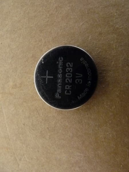
Y8YSCIOANT
Apr 01, 2014Wireless cycle computer
Equipment Class
DXX - Part 15 Low Power Communication Device Transmitter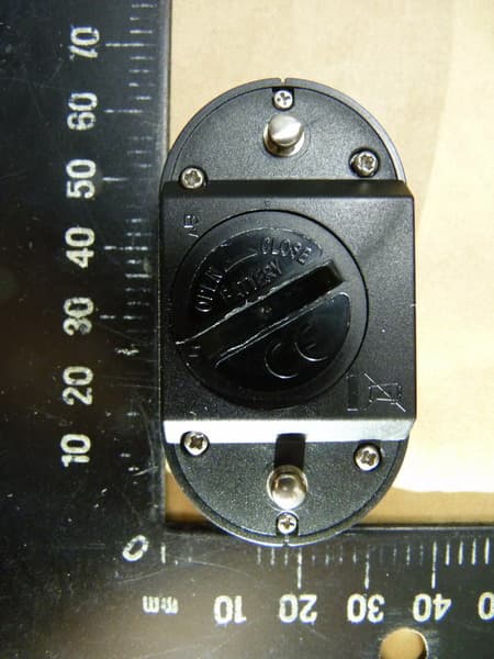
Y8YBH20
Jul 31, 2013WIRELESS CYCLE COMPUTER TRANSMITTER
Equipment Class
DTS - Digital Transmission System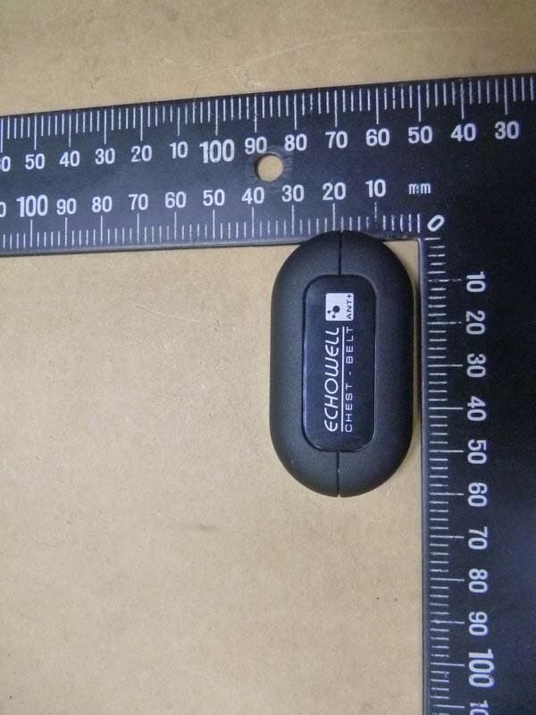
Y8YGH20
Sep 18, 2012WIRELESS CYCLE COMPUTER TRANSMITTER
Equipment Class
DXX - Part 15 Low Power Communication Device Transmitter