YAMDS-6210VC4DMR Trunking base station
Hytera Communications Corporation Limited
Click to zoom
Application Details
- Equipment Class
- TNB - Licensed Non-Broadcast Station Transmitter
- Date of Grant
- May 07, 2012
- Application Purpose
- Original Equipment
- Date of Application
- May 06, 2012
- Equipment Note
- DMR Trunking base station
- Frequency Range
- 136.02500000 - 173.97500000
- Country
- China
Documents & Files
Document Text
Text extracted from the exhibit documents filed with the FCC. Open a document above to read the original.
Users Manual
DS-6210VC4 Base Station Owner's Manual Version: V00 Release Date: July 29 th , 2011 Copyright Information Hytera is the trademark or registered trademark of Hytera Communications Co., Ltd. (the Company) in PRC and/or other countries or areas. The Company retains the ownership of its trademarks and product names. All other trademarks and/or product names that may be used in this manual are properties of their respective owners. The product described in this manual may include the Company’s computer programs stored in memory or other media. Laws in PRC and/or other countries or areas protect the exclusive rights of the Company with respect to its computer programs. The purchase of this product shall not be deemed to grant, either directly or by implication, any rights to the purchaser regarding the Company’s computer programs. Any of the Company’s computer programs may not be copied, modified, distributed, decompiled, or reverse-engineered in any manner without the prior written consent of the Company. Disclaimer The Company endeavors to achieve the accuracy and completeness of this manual, but no warranty of accuracy or reliability is given. All the specifications and designs are subject to change without notice due to continuous technology development. No part of this manual may be copied, modified, translated, or distributed in any manner without the express written permission of us. If you have any suggestions or would like to learn more details, please visit our website at: http://www.hytera.com . DS-6210VC4 Base Station Owner's Manual Contents i Contents Preface ....................................................................................................................................................1 1. Checking Items in the Package .........................................................................................................2 2. Product Controls ................................................................................................................................3 2.1 Base Station Interface Unit .............................................................................................................3 2.1.1 Antenna Connector ...............................................................................................................3 2.1.2 Extended Interface Board .....................................................................................................4 2.1.3 Power Supply Module ...........................................................................................................5 2.2 Cartridge .........................................................................................................................................5 2.3 Channel Unit ...................................................................................................................................5 2.3.1 Function ................................................................................................................................6 2.3.2 Front Panel ...........................................................................................................................6 2.3.3 LED Indicator ........................................................................................................................7 2.4 Base Station Controller Unit (BSCU) ..............................................................................................8 2.4.1 Function ................................................................................................................................9 2.4.2 Front Panel ...........................................................................................................................9 2.4.3 LED Indicator ......................................................................................................................10 2.4.4 Power Support Unit (PSU) ..................................................................................................11 2.4.5 Function .............................................................................................................................. 11 2.4.6 Front Panel .........................................................................................................................12 2.4.7 LED Indicator ......................................................................................................................13 2.4.8 Interconnect Backboard (ICB).............................................................................................13 2.4.9 Front Side ...........................................................................................................................14 2.4.10 Back Side..........................................................................................................................14 2.5 Fan Unit (FAN)..............................................................................................................................16 2.5.1 Front Panel .........................................................................................................................16 2.5.2 LED Indicator ......................................................................................................................17 2.5.3 Rear Panel..........................................................................................................................17 2.6 Divider Unit (DIU)..........................................................................................................................18 2.6.1 Function ..............................................................................................................................18 2.6.2 Front Panel .........................................................................................................................19 2.6.3 Rear Panel..........................................................................................................................19 2…
Text truncated - open the document above for the full version.
Block Diagram
BSCU Block Diagram 1. Block Diagram Panel Power Process Main Control Module Monitor Module Clock Buffer (1Hz) Backplane Connector GPS Process Reset Button LED SMA DB9 Switching Module RJ45 The BSCU has the following functions: Clock synchronization The GPS module gets the time information from the received GPS signal from SMA board, and then transmits it to each CHU via the clock buffering module and interconnection board interfaces. Monitor The network management agent software in the main control module collects the monitoring information from the BSCU and other modules through the monitoring module and interconnect board interfaces, and then reports them to the higher network management agent through the switching module and interconnect board interfaces. Protocols process The protocol process software in the main control module interconnects with the CHU and EIB through the switching module and interconnect board interfaces.It can receive the uplink signaling 1 PDT Base Station Block Diagram Block Diagram ICB CHU1 CHU2 CHU3 CHU4 BSCU1 BSCU2 FAN DIU COM PSU1 PSU2 EIB Power Input The base station has the following functions: Signaling and service process Downlink signaling and service The data packet from the core network enters the system via the EIB, and then is transferred to the BSCU through the ICB, afterwards, it is sent to the CHU for generating the RF signal via the ICB; finally the signal is transmitted by the TX antenna after combing by the COM. Uplink signaling and service The RF signal passes through the DIU to enter the system via RX or diversity antenna, and then is processed by the CHU. Afterwards, the processed signaling or service is transferred to the BSCU via the ICB. Finally the BSCU processes the received data and send it to the core network via the ICB and EIB. Monitor The BSCU collects all monitoring data from the CHU, PSU, DIU, EIB and FAN by the ICB, and report them to the higher network management agent by the ICB and EIB. In addition, it can receive the command from the higher network management agent by the ICB and EIB, and carry it out by the ICB. Power supply 1 Block Diagram PDT Base Station 2 The utility power or DC power (-48V) is sent to the system by the power input terminal, and then to the PSU by the ICB. Afterwards, it converts into internal power source for the system after processing by the PSU. Finally it supplies power to the CHU, BSCU, DIU and FAN by the ICB. ICB Block Diagram 1. Block Diagram ICB Synchronization Interconnection Bus Synchronization Interconnection Bus Signaling and Service Interconnection Bus CHU Connector x4BSCU Connector x2PSU Connector x2 Power Bus AC Connector DC Connector Channel Extension Connector Monitor Extension Connector Core Network Connector Power Output Connector The ICB has the following functions: Interconnection between signaling and service The signaling and service interconnection bus is used to connect the BSCU to the CHU, and also connected to the EIB for exchanging information with the core network. Monitor interconnection It can connect the monitoring data from the CHU, PSU, FAN and DIU to the BSCU through the monitoring bus and monitor extension connector, and report to the network management center through the core network. Synchronization interconnection It can allocate the synchronization information output from the BSCU to the CHU through the synchronization interconnection bus and channel extension connector, and send the external synchronization information from the core network connector to the BSCU 1 Block Diagram ICB 2 Power Supply The DC power from the PSU is allocated to each CHU and BSCU by the power bus, and to the DIU and FAN by the power output connector. The AC power connector is used to send the utility power to the system and to the PSU by the PSU connector. FAN Block Diagram 1. Block Diagram Power Process Monitor Module LED Fan Module Fan Module DB9 Power Connector External Temp. Input The FAN has the following functions: Monitor the operating status of the FAN It can report the temperature and fan speed via the DB9 interface, and receive the command from the higher network management agent to adjust the FAN parameters. Heat dissipation It can drive the fan module in real time according to external temperature, current speed, network management configuration and etc. Power process The power supply module can convert the single DC power into the desired DC power for each circuit. 1 EIB Block Diagram 1. Block Diagram LAN&E1 LANA LANB E1-TX1 E1-RX1 E1-1 E1-2 E1-TX1 E1-RX1 E1-1 E1-2 AUX LAN1 LAN2 E1-TX2 E1-RX2 CAN RS485 AUX LAN1 LAN2 E1-TX2 E1-RX2 CAN RS485 Inside Cabinet Outside Cabinet Lightning Protection Lightning Protection Lightning Protection Lightning Protection Lightning Protection Lightning Protection Lightning Protection Lightning Protection The EIB has the following functions: Interconnection between service data and signaling Interconnecting with the internet The signaling and service data sent by the base station to the core network first go through from the BSCU to the EIB via the LAN&E1 interface, and then to the router in the base station via the 1 Block Diagram EIB LANA or LANB interface in the inner side of the cabinet; afterwards they enters the LAN1 or LAN2, and lightning protection interface in the inner side of the cabinet; finally they are fed to the core network through LAN1 or LAN2 in the outer side of the cabinet. The signaling and service data sent by the core network to the base station first enter the cabinet via the LAN1 or LAN2 in the outer side of the cabinet, and then go through the lightning protector to the router via the LAN1 or LAN2 in the inner side of the cabinet, finally they are fed to the BSCU via the LANA or LANB, and LAN& EI interface. Interconnecting with EI The signaling and data service sent by the base station to the core network first go through from the BSCU to the EIB via LAN&EI interface, and then to t…
Text truncated - open the document above for the full version.
Cover Letter(s)
Hytera Communications Corporation Ltd. Add: HYT Tower, Hi-Tech Industrial Park North, Nanshan District, Shenzhen China. 518057 Tel: +86-0755-26972999 Fax: +86-0755-86137130 Justification Letter Date: 2012-4-5 FEDERAL COMMUNICATIONS COMMISSIONS Authorization and Evaluation Division 7435 Oakland Mills Road Columbia, MD 21046 FCC ID: YAMDS-6210VC4 Model number: DS-6210VC4 To whom it may concern: We, Hytera Communications Corporation Ltd., acknowledge that this device will not be marketed to USA users with the frequency band which is not allowed by rule part 90.and it is a violation of FCC rules if this device is operated on unauthorized frequencies inside the U.S.A. We, Hytera Communications Corporation Ltd., acknowledge this equipment meets the requirements of FCC Rules, Parts 90.203 (e) and (g) as applicable. Programming of this product's transmit frequencies can be performed ONLY by the manufacturer or by service or maintenance personnel. The operator cannot program transmit frequencies using the equipment's external operation. Client’s signature: Lei Xiong General Director
External Photos
EXHIBIT B - EUT EXTERNAL PHOTOGRAPHS EUT – Front View EUT – Front Open View EUT – Rear View EUT – Rear Open View EUT – Left Side View EUT – Right Side View EUT – Top View Antenna Connector
ID Label/Location Info
EXHIBIT A - FCC ID LABELING AND LOCATION FCC ID Label FCC ID Label Location The label shown shall be permanently affixed at a conspicuous location on the device and be readily visible to the user at the time purchase (Labeling requirements per 2.925)
Internal Photos
EXHIBIT C - EUT INTERNAL PHOTOGRAPHS EUT – BSCU External view EUT – BSCU Cover off View EUT – BSCU Main Board Top View EUT – BSCU Main Board Bottom View EUT – BSCU Control Module Top View EUT – CHU External View EUT – CHU Cover off View EUT – CHU CHB-MB Top View EUT – CHU CHB-MB Bottom View EUT – CHU CHB Top View EUT – CHU CHB Bottom View EUT – CHU TX Board Top View EUT – CHU TX Board Bottom View EUT – CHU RX Board Top View EUT – CHU RX Board Bottom View EUT – DIU External View EUT – DIU Cover off View EUT – DIU Main Board Top View EUT – DIU Main Board Bottom View EUT – EIB External View EUT – FANS External View EUT – ICB Top View EUT – ICB Bottom View EUT – PSU External View EUT – Combiner External View
Operational Description
After going through the antenna, the service signal reaches DIU and CHU, where the signal will be delivered to baseband after appropriate processing. Then the baseband will send the service signal to BSCU for soft switch. Afterwards, the signal will be sent back via ICB to baseband, which would convert it into HF signal and send it to the transmitter. Finally, the transmitter will deliver the HF service signal to antenna via COM。
Parts List/Tune Up Info
Parts List ICB 4. Parts List No. Ref No. Part NumberDescription 1PCB41000001016C0PCB 2J15204080200010Interconnect backboard connector 3J35204080200010Interconnect backboard connector 4J55204080200010Interconnect backboard connector 5J75204080200010Interconnect backboard connector 6J25204080200000Interconnect backboard connector 7J45204080200000Interconnect backboard connector 8J65204080200000Interconnect backboard connector 9J85204080200000Interconnect backboard connector 10J95204200200030Interconnect backboard connector 11J115204200200030Interconnect backboard connector 12J105204200200020Interconnect backboard connector 13J125204200200020Interconnect backboard connector 14J395202024200000Board-to-wire connector 15J405202024200000Board-to-wire connector 16J415202024200000Board-to-wire connector 17J425202024200000Board-to-wire connector 18J435202024200000Board-to-wire connector 19J465202024200000Board-to-wire connector 20J475202024200000Board-to-wire connector 21J525202024200000Board-to-wire connector 22H456300136000000Positioning post 23H466300136000000Positioning post 24H476300136000000Positioning post 25H486300136000000Positioning post 26H496300136000000Positioning post 27H506300136000000Positioning post 28H516300136000000Positioning post 29H536300136000000Positioning post 30H546300136000000Positioning post 31H427102506002009Machine screw 32H437102506002009Machine screw 33H447102506002009Machine screw 34H457102506002009Machine screw 35H467102506002009Machine screw 36H477102506002009Machine screw 37H487102506002009Machine screw 38H497102506002009Machine screw 14 ICBParts List 15 No. Ref No. Part NumberDescription 39H507102506002009Machine screw 40H517102506002009Machine screw 41H537102506002009Machine screw 42H547102506002009Machine screw PSUParts List 4.Parts List No.Ref No.Print No.Part NumberDescription 1C1T4E31010510400600.1uF 2C10T3E31040847500404.7uF 3C11T3E31010610400300.1uF 4C12T4D31010510400600.1uF 5C13T4D310107106000010uF 6C14T4E310107106000010uF 7C15T3E310107106000010uF 8C16T3E310107106000010uF 9C17T3E31010510400600.1uF 10C18T3E31010510400600.1uF 11C19T4E31010510400600.1uF 12C2T4E31010510400600.1uF 13C20T3E31040810400000.1uF 14C21T4E31010510400600.1uF 15C22T4E31010510400600.1uF 16C23T3E31010510400600.1uF 17C24T3D31010610500601uF 18C25T3C31010610500601uF 19C26T3D31010610500601uF 20C27T3C31010610500601uF 21C28T4F31010510400600.1uF 22C29T3F31010510400600.1uF 23C3T4D31010510400600.1uF 24C30T3D31010610500601uF 25C31T4D31010510400600.1uF 26C32T4D3101053310020330pF 27C33T5D31010610300100.01uF 28C34T6D3104201070020100uF/10V 29C35T7D3104201070020100uF/10V 30C36T8D31010610300100.01uF 31C37T9D3104991070090100uF/20V 32C38T10D3104991070090100uF/20V 33C4T4E31010510400600.1uF 34C40T3F31010510400600.1uF 35C41T3B310108106001010uF 36C42T4D3101053310020330pF 37C43T3E31010610500601uF 38C44T3F31010510400600.1uF 39C45T3C31010610500601uF 7 Parts List PSU No.Ref No.Print No.Part NumberDescription 40C46T3C31010510400600.1uF 41C47T3F31010510400600.1uF 42C48T4A310109226001022uF 43C49T4B3104201070020100uF/10V 44C5T4E31010510400600.1uF 45C50T3B31010510400600.1uF 46C51T3F31010510400600.1uF 47C52T3F31010510400600.1uF 48C54T4F31010510400600.1uF 49C55T3F31010510400600.1uF 50C56T4F31010510400600.1uF 51C57T3F31010510400600.1uF 52C58T3A31010510400600.1uF 53C59T3D3101053310020330pF 54C6T4E31010510400600.1uF 55C60T3D3101053310020330pF 56C61T3D3101051010030100pF 57C62T3D3101051010030100pF 58C63T3E31010610400300.1uF 59C64T3E31040847500404.7uF 60C65T4A31010510400600.1uF 61C66T4A31010610300100.01uF 62C67T4A31010510400600.1uF 63C68T4A310108106001010uF 64C7T3E310106200000020pF 65C8T3D31010510400600.1uF 66C9T3E310106200000020pF 67D1T3E3303010500090Diode 68D101T3B3307110100070LED 69D103T3F3310350100000Zener diode 70D104T3F3310350100000Zener diode 71D12T3B3311300000000Schottky diode 72D13T4B3311300000000Schottky diode 73D14T3B3310200600000TVS diode 74D15T3A3311100300000Diode 75D17T4D3310200600000TVS diode 76D18T3D3310200600000TVS diode 77D2T3E3303010500090Diode 78D20T3D3399040600010ESD protection diode 79D21T4B3301330200000Diode 80D22T3B3301330200000Diode 81D3T3D3310350100000Zener diode 8 PSUParts List No.Ref No.Print No.Part NumberDescription 82D30T4D3310200600000TVS diode 83D31T3D3310200600000TVS diode 84D4T3C3310350100000Zener diode 85D5T3D3310350100000Zener diode 86D6T3C3310350100000Zener diode 87D7T3D3310350100000Zener diode 88D8T3D3307110100080LED 89F1T3B4002000000020Fuse 90J10T2A5205002100200Connector 91J11T2B5205002100200Connector 92J13T2F5205003100170Connector 93J14T2D5205002100200Connector 94J19T3F5202002200019Connector 95J2T4E5208020200070Connector 96J21T4@5202012200030Connector 97J22T4F5202002200019Connector 98J6T1B5202004200140Connector 99J7T1D5202004200140Connector 100J8T2B5205002100200Connector 101J9T2C5205002100200Connector 102L1T3E3213212102000Inductor 103L2T3A3211799153010Inductor 104L3T3F3221507600000Inductor 105L4T3F3221507600000Inductor 106L5T3F3221507600000Inductor 107L6T4F3221507600000Inductor 108L7T4F3221507600000Inductor 109L8T4F3221507600000Inductor 110Q1T4C3401002000290Transistor 111Q2T4C3401002000290Transistor 112Q3T4D3401002000290Transistor 113Q4T4D3401002000290Transistor 114R1T4E30010647200504.7K 115R100T3C30010610200101K 116R101T4C309906499904049.9R 117R102T3D30010610200101K 118R103T4D309906499904049.9R 119R104T3D30010647200504.7K 120R105T4D300106330000033R 121R106T3D300106330000033R 122R107T4D300106330000033R 123R13T4D300106330000033R 9 Parts List PSU No.Ref No.Print No.Part NumberDescription 124R14T4D300106330000033R 125R16T2D300106103000010K 126R17T2D300106103000010K 127R18T2D300106103000010K 128R19T2E300106103000010K 129R2T4E300106103000010K 130R20T4E300106330000033R 131R21T2D300106330000033R 132R22T2D300106330000033R 133R23T2D300106330000033R 134R24T2E300106330000033R 135R25T3D300106103000010K 136R28T3D300106103000010K 137R29T3E300106103000010K 138R30T3E30010647200504.7K 139R31T4D300106330000033R 140R32T4D300107100000010R 141R33T4D300107100000010R 142R34T3D300107100000010R 143R35T3D3001…
Text truncated - open the document above for the full version.
Parts List/Tune Up Info
Tune-up Procedure 1、 Receive parameters Item Test Condition Test equipment Test Part Specification/Remark Sensitivity input level:-119dBm Signal generator Receive Port P I =-119dBm,BER≤5% Spurious Radiations Spectrum analyzer 1. Resolution BW:100kHz; 2. Video BW: 300kHz Spectrum analyzer Receive Port 9 kHz to 1 GHz≤ -57dBm; 1GHz to 12.75 GHz≤ -47dBm; 2、 Transmitter parameters Item Test Condition Test equipment Test Part Specification/Remark Frequency Stability Spectrum analyzer 1.Resolution BW:30kHz; 2.Video BW: 100kHz Spectrum analyzer Transmitter Port ≤±1kHz Emission Mask Spectrum analyzer 1.Resolution BW:300Hz; 2.Video BW:1kHz Spectrum analyzer Transmitter Port RF Output Power Spectrum analyzer 1.Resolution BW:30kHz; 2.Video BW: 100kHz Spectrum analyzer Transmitter Port 43.5dBm±1.5dB Adjacent channel power Spectrum analyzer 1.Resolution BW:30Hz; 2.Video BW:1kHz Spectrum analyzer Transmitter Port ≤-60dB Occupied Bandwidth Spectrum analyzer 1.Resolution BW:100Hz; 2.Video BW:300Hz Spectrum analyzer Transmitter Port ≤8.5kHz Spectrum emission mask test Spectrum analyzer 1.Resolution BW:100kHz; 2.Video BW: 300kHz Spectrum analyzer Transmitter Port 9 kHz to 1 GHz≤ -36dBm; 1GHz to 12.75 GHz≤ -30dBm; After going through the antenna, the service signal reaches DIU and CHU, where the signal will be delivered to baseband after appropriate processing. Then the baseband will send the service signal to BSCU for soft switch. Afterwards, the signal will be sent back via ICB to baseband, which would convert it into HF signal and send it to the transmitter. Finally, the transmitter will deliver the HF service signal to antenna via COM。 1、 Open the test tool exe , then input IP address of CHU to the ”Listen Remote IP ” pane, click the “Open udp” button; 2、 then find the Read Frequency pane, input the FPGA &STM32 frequency after this setup click the “Write frequency” button; 3、 fixed Read power pane used “Write power” button then open it; 4、 Input the RX Frequency to the ”Read Frequency” pane, click the “Write frequency” button.
RF Exposure Info
Bay Area Compliance Laboratories Corp. (Shenzhen) Report No.: R1DG120323004-00 FCC Part 90 Page 7 of 25 FCC §1.1307 (b) (1) & §2.1091- MAXIMUM PERMISSIBLE EXPOSURE (MPE) Applicable Standard According to 1.1307 (b)(1), 2.1091 systems operating under the provisions of this section shall be operated in a manner that ensures the public is not exposed to RF energy level in excess of the communication guidelines. Limits for General Population/Uncontrolled Exposure Limits for General Population/Uncontrolled Exposure Frequency Range (MHz) Electric Field Strength (V/m) Magnetic Field Strength (A/m) Power Density (mW/cm 2 ) Averaging Time (minutes) 0.3-1.34 614 1.63 *(100) 30 1.34-30 824/f 2.19/f *(180/f 2 ) 30 30-300 27.5 0.073 0.2 30 300-1500 / / f/1500 30 1500-100,000 / / 1.0 30 f = frequency in MHz * = Plane-wave equivalent power density MPE Calculation Predication of MPE limit at a given distance S = PG/4πR 2 Where: S = power density (in appropriate units, e.g. mW/cm 2 ); P = power input to the antenna (in appropriate units, e.g., mW); G = power gain of the antenna in the direction of interest relative to an isotropic radiator R = distance to the center of radiation of the antenna (appropriate units, e.g., cm); Antenna Gain Conducted Power Frequency (MHz) (dBi) (numeric) (dBm) (mW) Evaluation Distance (cm) Power Density (mW/cm 2 ) MPE Limit (mW/cm 2 ) 136.025 8.5 7.08 38.31 6776 200 0.0955 0.2 155.025 8.5 7.08 38.84 7656 200 0.1079 0.2 173.975 8.5 7.08 38.81 7603 200 0.1071 0.2 Result: Pass
Schematics
55 44 33 22 11 D D C C B B A A BSCU2 <<>> EC1.IRU1BSCU1 <<>> EC1.IRU1BSCU2 <<>> EC1.IRU2BSCU1 <<>> EC1.IRU2 BSCU1 <<>> EC2.IRU2BSCU1 <<>> EC2.IRU1BSCU1 <<>> EC3.IRU1 BSCU2 <<>> EC2.IRU2 BSCU2 <<>> EC2.IRU1BSCU1 <<>> EC3.IRU2 BSCU2 <<>> EC3.IRU2BSCU2 <<>> EC3.IRU1 GND_48V DC48V N AC220V/110V PE BSC_V BSC_V BSC_V BSC_V BSC_V BSC_V IRU1_TX1_PIRU1_TX1_N IRU1_RX1_PIRU1_RX1_NIRU1_CLK1_PIRU1_CLK1_NIRU1_CNT1_PIRU1_CNT1_NIRU1_CLK2_PIRU1_CLK2_NIRU1_CNT2_PIRU1_CNT2_N IRU1_TX2_PIRU1_TX2_N IRU1_RX2_PIRU1_RX2_NIRU2_CLK1_PIRU2_CLK1_NIRU2_CNT1_PIRU2_CNT1_NIRU2_CLK2_PIRU2_CLK2_NIRU2_CNT2_PIRU2_CNT2_N IRU2_TX2_PIRU2_TX2_N IRU2_RX2_PIRU2_RX2_N IRU2_TX1_PIRU2_TX1_N IRU2_RX1_PIRU2_RX1_N IRU3_CLK1_PIRU3_CLK1_NIRU3_CNT1_PIRU3_CNT1_N IRU3_TX1_PIRU3_TX1_N IRU3_RX1_PIRU3_RX1_NIRU4_CLK1_PIRU4_CLK1_NIRU4_CNT1_PIRU4_CNT1_N IRU4_TX1_PIRU4_TX1_N IRU4_RX1_PIRU4_RX1_NIRU5_CLK1_PIRU5_CLK1_NIRU5_CNT1_PIRU5_CNT1_N IRU5_TX1_PIRU5_TX1_N IRU5_RX1_PIRU5_RX1_N IRU6_CLK1_PIRU6_CLK1_NIRU6_CNT1_PIRU6_CNT1_N IRU6_TX1_PIRU6_TX1_N IRU6_RX1_PIRU6_RX1_NIRU3_CLK2_PIRU3_CLK2_NIRU3_CNT2_PIRU3_CNT2_N IRU3_TX2_PIRU3_TX2_N IRU3_RX2_PIRU3_RX2_NIRU4_CLK2_PIRU4_CLK2_NIRU4_CNT2_PIRU4_CNT2_N IRU4_TX2_PIRU4_TX2_N IRU4_RX2_PIRU4_RX2_N IRU5_CLK2_PIRU5_CLK2_NIRU5_CNT2_PIRU5_CNT2_N IRU5_TX2_PIRU5_TX2_N IRU5_RX2_PIRU5_RX2_NIRU6_CLK2_PIRU6_CLK2_NIRU6_CNT2_PIRU6_CNT2_N IRU6_TX2_PIRU6_TX2_N IRU6_RX2_PIRU6_RX2_N BSCU1_ETH_TX1_PBSCU1_ETH_TX1_N BSCU1_ETH_RX1_N BSCU1_ETH_RX1_P BSCU1_ETH_CLK1_N BSCU1_ETH_CLK1_P BSCU1_ETH_CNT1_N BSCU1_ETH_CNT1_P BSCU1_ETH_RX2_N BSCU1_ETH_RX2_P BSCU1_ETH_CLK2_N BSCU1_ETH_CLK2_P BSCU1_ETH_CNT2_N BSCU1_ETH_CNT2_PBSCU1_ETH_TX2_PBSCU1_ETH_TX2_N BSCU1_E1_RX1_N BSCU1_E1_RX1_PBSCU1_E1_TX1_PBSCU1_E1_TX1_N BSCU1_E1_RX2_N BSCU1_E1_RX2_PBSCU1_E1_TX2_PBSCU1_E1_TX2_N BSCU2_E1_RX2_N BSCU2_E1_RX2_PBSCU2_E1_TX2_PBSCU2_E1_TX2_N BSCU2_ETH_RX1_N BSCU2_ETH_RX1_P BSCU2_ETH_CLK1_N BSCU2_ETH_CLK1_P BSCU2_ETH_CNT1_N BSCU2_ETH_CNT1_P BSCU2_E1_RX1_N BSCU2_E1_RX1_PBSCU2_E1_TX1_PBSCU2_E1_TX1_NBSCU2_ETH_TX1_P BSCU2_ETH_RX2_N BSCU2_ETH_RX2_P BSCU2_ETH_CLK2_N BSCU2_ETH_CLK2_P BSCU2_ETH_CNT2_N BSCU2_ETH_CNT2_PBSCU2_ETH_TX2_PBSCU2_ETH_TX2_NBSCU2_ETH_TX1_N BSCU2_E1_RX2 BSCU2_E1_TX2 BSCU1_E1_RX2BSCU2_E1_RX1 BSCU1_E1_TX2 BSCU1_E1_RX1 BSCU1_E1_TX1BSCU2_E1_TX1 RS485_N CAN_LCAN_H RS485_P CAN_LCAN_H RS485_NRS485_P SW_HSW_L A6B6C6D6 C5A5D5B5 C4A4D4B4 C3A3D3B3 C2A2D2B2 C1A1D1B1 70232-116LF J47 A6B6C6D6 C5A5D5B5 C4A4D4B4 C3A3D3B3 C2A2D2B2 C1A1D1B1 70232-116LF J47 A1 A1 B1 B1 C1 C1 D1 D1 A2 A2 B2 B2 C2 C2 D2 D2 A3 A3 B3 B3 C3 C3 D3 D3 A4 A4 B4 B4 C4 C4 D4 D4 A5 A5 B5 B5 C5 C5 D5 D5 A6 A6 B6 B6 C6 C6 D6 D6 12 34 J53 CON2X2 12 34 J53 CON2X2 1 2 3 4 J29 DB9_M J29 DB9_M 123456789 1011 1 2 H46 CN-68-1-1 1 2 H46 CN-68-1-1 12 H28H28 1 H25H25 1 1 2 H48 CN-68-1-1 1 2 H48 CN-68-1-1 12 J33 DB9_F J33 DB9_F 123456789 1011 H20H20 1 H36H36 1 H6H6 1 H14H14 1 H1H1 1 A6B6C6D6 C5A5D5B5 C4A4D4B4 C3A3D3B3 C2A2D2B2 C1A1D1B1 70232-116LF J41 A6B6C6D6 C5A5D5B5 C4A4D4B4 C3A3D3B3 C2A2D2B2 C1A1D1B1 70232-116LF J41 A1 A1 B1 B1 C1 C1 D1 D1 A2 A2 B2 B2 C2 C2 D2 D2 A3 A3 B3 B3 C3 C3 D3 D3 A4 A4 B4 B4 C4 C4 D4 D4 A5 A5 B5 B5 C5 C5 D5 D5 A6 A6 B6 B6 C6 C6 D6 D6 1 2 H43 CN-68-1-1 1 2 H43 CN-68-1-1 12 H31H31 1 H38H38 1 123456 J45 DC48V 123456 J45 DC48V 123456 1 2 H42 CN-68-1-1 1 2 H42 CN-68-1-1 12 H16H16 1 H2H2 1 A6B6C6D6 C5A5D5B5 C4A4D4B4 C3A3D3B3 C2A2D2B2 C1A1D1B1 70232-116LF J42 A6B6C6D6 C5A5D5B5 C4A4D4B4 C3A3D3B3 C2A2D2B2 C1A1D1B1 70232-116LF J42 A1 A1 B1 B1 C1 C1 D1 D1 A2 A2 B2 B2 C2 C2 D2 D2 A3 A3 B3 B3 C3 C3 D3 D3 A4 A4 B4 B4 C4 C4 D4 D4 A5 A5 B5 B5 C5 C5 D5 D5 A6 A6 B6 B6 C6 C6 D6 D6 1 2 H44 CN-68-1-1 1 2 H44 CN-68-1-1 12 1 2 H45 CN-68-1-1 1 2 H45 CN-68-1-1 12 1 2 H47 CN-68-1-1 1 2 H47 CN-68-1-1 12 H29H29 1 H23H23 1 J28 DB9_M J28 DB9_M 123456789 1011 A6B6C6D6 C5A5D5B5 C4A4D4B4 C3A3D3B3 C2A2D2B2 C1A1D1B1 70232-116LF J52 A6B6C6D6 C5A5D5B5 C4A4D4B4 C3A3D3B3 C2A2D2B2 C1A1D1B1 70232-116LF J52 A1 A1 B1 B1 C1 C1 D1 D1 A2 A2 B2 B2 C2 C2 D2 D2 A3 A3 B3 B3 C3 C3 D3 D3 A4 A4 B4 B4 C4 C4 D4 D4 A5 A5 B5 B5 C5 C5 D5 D5 A6 A6 B6 B6 C6 C6 D6 D6 1 2 H49 CN-68-1-1 1 2 H49 CN-68-1-1 12 H33H33 1 H34H34 1 H12H12 1 12 34 J36 CON2X2 12 34 J36 CON2X2 1 2 3 4 12 34 J38 CON2X2 12 34 J38 CON2X2 1 2 3 4 A6B6C6D6 C5A5D5B5 C4A4D4B4 C3A3D3B3 C2A2D2B2 C1A1D1B1 70232-116LF J43 A6B6C6D6 C5A5D5B5 C4A4D4B4 C3A3D3B3 C2A2D2B2 C1A1D1B1 70232-116LF J43 A1 A1 B1 B1 C1 C1 D1 D1 A2 A2 B2 B2 C2 C2 D2 D2 A3 A3 B3 B3 C3 C3 D3 D3 A4 A4 B4 B4 C4 C4 D4 D4 A5 A5 B5 B5 C5 C5 D5 D5 A6 A6 B6 B6 C6 C6 D6 D6 H10H10 1 H5H5 1 H30H30 1 H37H37 1 1 2 H50 CN-68-1-1 1 2 H50 CN-68-1-1 12 1 2 H54 CN-68-1-1 1 2 H54 CN-68-1-1 12 12 34 J37 CON2X2 12 34 J37 CON2X2 1 2 3 4 H17H17 1 H7H7 1 A6B6C6D6 C5A5D5B5 C4A4D4B4 C3A3D3B3 C2A2D2B2 C1A1D1B1 70232-116LF J40 A6B6C6D6 C5A5D5B5 C4A4D4B4 C3A3D3B3 C2A2D2B2 C1A1D1B1 70232-116LF J40 A1 A1 B1 B1 C1 C1 D1 D1 A2 A2 B2 B2 C2 C2 D2 D2 A3 A3 B3 B3 C3 C3 D3 D3 A4 A4 B4 B4 C4 C4 D4 D4 A5 A5 B5 B5 C5 C5 D5 D5 A6 A6 B6 B6 C6 C6 D6 D6 12 34 J54 CON2X2 12 34 J54 CON2X2 1 2 3 4 SW1 SSGM640200 SW1 SSGM640200 1234 5678 H26H26 1 1 2 H51 CN-68-1-1 1 2 H51 CN-68-1-1 12 H24H24 1 H32H32 1 H19H19 1 H8H8 1 A6B6C6D6 C5A5D5B5 C4A4D4B4 C3A3D3B3 C2A2D2B2 C1A1D1B1 70232-116LF J46 A6B6C6D6 C5A5D5B5 C4A4D4B4 C3A3D3B3 C2A2D2B2 C1A1D1B1 70232-116LF J46 A1 A1 B1 B1 C1 C1 D1 D1 A2 A2 B2 B2 C2 C2 D2 D2 A3 A3 B3 B3 C3 C3 D3 D3 A4 A4 B4 B4 C4 C4 D4 D4 A5 A5 B5 B5 C5 C5 D5 D5 A6 A6 B6 B6 C6 C6 D6 D6 H9H9 1 H4H4 1 J34 DB9_F J34 DB9_F 123456789 1011 H21H21 1 H35H35 1 1234 J44 AC220V 1234 J44 AC220V 1234 H13H13 1 A6B6C6D6 C5A5D5B5 C4A4D4B4 C3A3D3B3 C2A2D2B2 C1A1D1B1 70232-116LF J39 A6B6C6D6 C5A5D5B5 C4A4D4B4 C3A3D3B3 C2A2D2B2 C1A1D1B1 70232-116LF J39 A1 A1 B1 B1 C1 C1 D1 D1 A2 A2 B2 B2 C2 C2 D2 D2 A3 A3 B3 B3 C3 C3 D3 D3 A4 A4 B4 B4 C4 C4 D4 D4 A5 A5 B5 B5 C5 C5 D5 D5 A6 A6 B6 B6 C6 C6 D6 D6 H15H15 1 H3H3 1 H27H27 1 H22H22 1 H18H18 1 H11…
Text truncated - open the document above for the full version.
Contact Information
Applicant
Ruifen Huang(Certification Engineer)
Test Firm
Bay Area Compliance Laboratories Corp. (Dongguan)John Chan
[email protected]86-769-86858888
Technical Specifications
| # | Rule Parts | Frequency Range | Power Output | Emission | Tolerance |
|---|---|---|---|---|---|
| 2 | 9 | 136.025 MHz - 173.975 MHz | 7.603 W | 9K31FXD | 2 ppm |
Other Applications from Hytera Communications Corporation Limited
YAMBP516LF
Aug 15, 2022Digital Portable Radio
Equipment Class
FRF - Part 95 Family Radio Face Held Transmitter
YAMBP5XXVHF
Mar 01, 2022Digital Portable Radio
Equipment Class
DSS - Part 15 Spread Spectrum Transmitter
YAMPNC360S
Jan 19, 2022PoC Radio
Equipment Class
DTS - Digital Transmission System
YAMHM78XUVS
Jul 28, 2021DIGITAL MOBILE RADIO
Equipment Class
TNB - Licensed Non-Broadcast Station Transmitter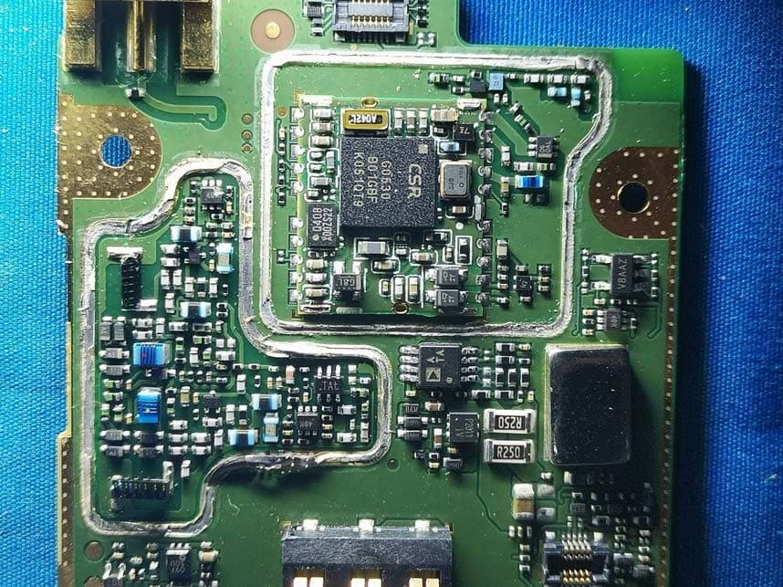
YAMHP6XXUMS
Jul 22, 2021Digital Portable Radio
Equipment Class
DTS - Digital Transmission System