YAMHP68XUMDigital Portable Radio
Hytera Communications Corporation Limited
Click to zoom
Application Details
- Equipment Class
- DTS - Digital Transmission System
- Date of Grant
- May 27, 2020
- Application Purpose
- Original Equipment
- Date of Application
- May 27, 2020
- Equipment Note
- Digital Portable Radio
- Frequency Range
- 2402.00000000 - 2480.00000000
- Country
- China
Documents & Files
Document Text
Text extracted from the exhibit documents filed with the FCC. Open a document above to read the original.
Users Manual
1. Product Overview 1.1 P roduct Layout No. Part Name No. Part Name 1 On-Off Key 12 Antenna 2 Push-to-Talk (PTT) Key 13 Microphone 3 Side Key 1 (SK1) 14 Back/Subgroup Key 4 Side Key 2 (SK2) 15 P2/End Key 5 Smart Knob 16 Navigation Key 6 LCD Display 17 Battery Latch 7 OK/Menu Key 18 Strap Hole 8 P1/Answer Key 19 Accessory connector 9 Numeric Keypad 20 Belt Clip 10 Speaker 21 Battery 11 LED Indicator 22 Charging Piece 1 2 1.2 Programmable Keys For enhanced convenience, you can request your dealer to program the following keys as shortcuts to radio features: SK1, Sk2, P1/Answer key, P2/End Key, Up key, and Down key. For details, consult your dealer. 3 2. Basic Operations 2.1 Charging the Battery Use the approved charger to charge the battery. Read the Safety Information Booklet before charging. The remaining lithium-ion battery power is limited to 30% pursuant to the new lithium battery shipment regulation approved by International Air Transport Association (IATA). Before initial use, charge the battery. You can charge either the standalone battery or the radio with battery attached. It is recommended that the radio remain powered off during charging. The LED indicator on the charger shows the charging status. For details, see the following table. LED Indicator Charging Status Glows red The battery is being charged. Glows orange The battery is charged to 90% or above. Glows green The battery is fully charged. Flashes red slowly No battery is placed on the charger. Flashes red rapidly The battery fails to be charged. 2.2 Turning the Radio On or Off 2.2.1 Turning the Radio On To turn the radio on, long press . 2.2.2 Turning the Radio Off To turn the radio off, long press . 2.3 Adjusting the Volume To increase or decrease the volume, rotate the Smart knob clockwise or counter-clockwise. 4 2.4 Selecting the Contact or Channel To select the contact or channel, press and then rotate the Smart knob. If you do not rotate the Smart knob after pressing it within 5s or if you press it again within 5s, you can rotate it to adjust the volume. 2.5 Locking or Unlocking the Keypad When the keypad is not in use, it is recommended that you lock it to avoid unintended operations. Auto Lock To allow the keypad to be locked automatically, go to Menu > Settings > Basic Settings > Keypad Lock to enable AutoLock, and then go to Timed to set the auto lock time. If you do not operate the radio or if the radio receives no call or message within the auto lock time, the keypad is locked automatically. Manual Lock or Unlock » Press the preprogrammed Keypad Lock key. » On the home screen, press the OK/Menu key, and then press . Keypad Lock Backup With this feature enabled by your dealer, the radio automatically saves the last settings of keypad lock upon power-off. You can go to Menu > Settings > Basic Settings > Keypad Lock > Optional Key to set whether the corresponding keys and knobs still work when the keypad is locked. 2.6 Using the Keypad You can use the keypad to enter contact aliases and IDs, or edit messages. To switch the input method, press . To enter special characters, press in alphabetic mode. To enter a space, press in alphabetic mode. 2.7 Switching the Operation Mode The radio can operate in conventional mode or trunking mode (enabled by your dealer). Manual Switch » Go to Menu > Mode, and then select the mode. 5 » Press the preprogrammed Operation Mode Switch key. » If the Zone/Subgroup Switch Mode feature is enabled, you can switch the operation mode by switching the contact through the menu or the Smart knob. Auto Switch The Mode Automatic Switch feature allows the radio to automatically switch the operation mode, so as to guarantee the normal communication of the radios in no-signal coverage areas or when the system fails. Go to Menu > Mode to enable Auto Switch, or press the preprogrammed Mode Auto Switch key. 2.7.1 Conventional Mode In conventional mode, a zone is a group of channels within the same operational area. The radio receives and transmits data and voice on the selected channel. 2.7.1.1 Selecting a Zone Go to Menu > Zone, select the zone, and then select Set Default. Press the preprogrammed Zone Up or Zone Down key. 2.7.1.2 Selecting a Channel A channel is used to receive and transmit data and voice. Before selecting a channel, make sure that the current zone contains the channel. Press and then rotate the Smart knob. Go to Menu > Zone, select the zone, and then select the channel. Press the preprogrammed Channel Up or Channel Down key. Press the preprogrammed Preset Channel key. If the Voice Notify feature is enabled, the radio automatically announces the current channel upon power-on and channel change. 2.7.2 Trunking Mode In trunking mode, the radio automatically hunts for available base stations (BS). During hunting, the LCD displays "Hunting...”. After registration, the radio can receive and transmit voice and data. 2.7.2.1 Selecting a Group or Private Contact To select a group contact or a private contact, do one of the following: 6 Press and then rotate the Smart knob. On the home screen, press the Back/Subgroup key or go to Menu > Subgroup, select the subgroup, and then select the group or private contact. Press the preprogrammed Group/Private Up or Group/Private Down key. 2.7.2.2 Selecting a Subgroup A subgroup consists of multiple groups or private contacts. To select a subgroup, do either of the following: On the home screen, press the Back/Subgroup key or go to Menu > Subgroup, select the subgroup, and then select Set Default. Press the preprogrammed Subgroup Up or Subgroup Down key. 7 3. Status Indications 3.1 LCD Icons Icon Radio Status The fuller the battery bar is, the stronger the battery power remains. The battery power is low. The battery power runs out. Recharge or replace the battery. The radio detects no signal. More bars indicate stronger signal strength. The radio operates in low power mode. The radio operates in high power m…
Text truncated - open the document above for the full version.
Cover Letter(s)
QA-FR-170-B H ytera Communications Corporation Limited Add: Hytera Tower, Hi-Tech Industrial Park North, 9108# Beihuan Road, Nanshan District, Shenzhen, 518057 China Tel: +86-755-26972999 Fax: +86-755-86139020 Email: [email protected] FCC Authorization Date: 2020-02-07 FEDERAL COMMUNICATIONS COMMISSION Authorization an d Evaluation Division 74 35 Oakland Mills Road Columbia, MD 21046 Subject: Agent Authorization To whom it may concern: We, Hytera Communications Corporation Limited, hereby authorizes Bay Area Compliance Laboratories Corporation to act on its behalf in all matters relating to application for Equipment authorization, including the signing of all documents relating to these matters. All acts carried out by Bay Area Compliance Laboratories Corp. on our behalf shall have the same effect as our own action. We, the undersigned, hereby certify that we are not subject to a denial of federal benefits, that includes FCC benefits, pursuant to Section 5301 of the Anti-Drug Abuse Act of 1988, 21 U.S.C. 862. This authorization is valid until further written notice from the applicant. Sincerely Yours, Signature: Tiantian Chen Certification Engineer
Cover Letter(s)
QA- FR-172-A Hytera Communications Corporation Limited Add: Hytera Tower, Hi-Tech Industrial Park North, 9108# Beihuan Road, Nanshan District, Shenzhen, 518057 China Tel: +86-755-26972999 Fax: +86-755-86139020 Email: [email protected] FCC Confidential Authorization Date: 2020-02-07 FEDERAL COMMUNICATIONS COMMISSION Authorization and Evaluation Division 7435 Oakland Mills Road Columbia, MD 21046 Subject: Confidentiality Request regarding application for certification of FCC ID: YAMHP68XUM In accordance with Sections 0.457 and 0.459 of the Commission’s Rules, Hytera Communications Corporation Limited, hereby requests long-term confidential treatment of information accompanying this application as outlined below: Block Diagram Schematics Operation Description Parts List/Tune-up Procedure (for licensed devices) The above materials contain proprietary and confidential information not customarily released to the public. The public disclosure of these materials provides unjustified benefits to its competitors in the market. Sincerely, Signature: Tiantian Chen Certification Engineer
Cover Letter(s)
Hytera Communications Corporation Limited Add: Hytera Tower, Hi-Tech Industrial Park North, 9108# Beihuan Road,Nanshan District, Shenzhen, 518057 China Tel: +86-755-26972999 Fax: +86-755-86139020 Email: [email protected] DECLARATION OF SIMILARITY Date: 2020-02-07 FEDERAL COMMUNICATIONS COMMISSION Authorization and Evaluation Division 7435 Oakland Mills Road Columbia, MD 21046 Dear Sir or Madam: We, Hytera Communications Corporation Limited, hereby declare that the product: Digital Portable Radio, FCC ID: YAMHP68XUM models: HP680 Um, HP686 Um, HP688 Um, HP685 Um are electrically identical with the model: HP682 Um which was tested by BACL with the same electromagnetic emissions and electromagnetic compatibility characteristics. A description of the differences between those models and that are declared similar are as follows: They are the same product, and just the different model name, the rest are the same. Please contact me should there be need for any additional clarification or information. Best Regards, Signature: Printed Name: Tiantian Chen Title: Certification Engineer
External Photos
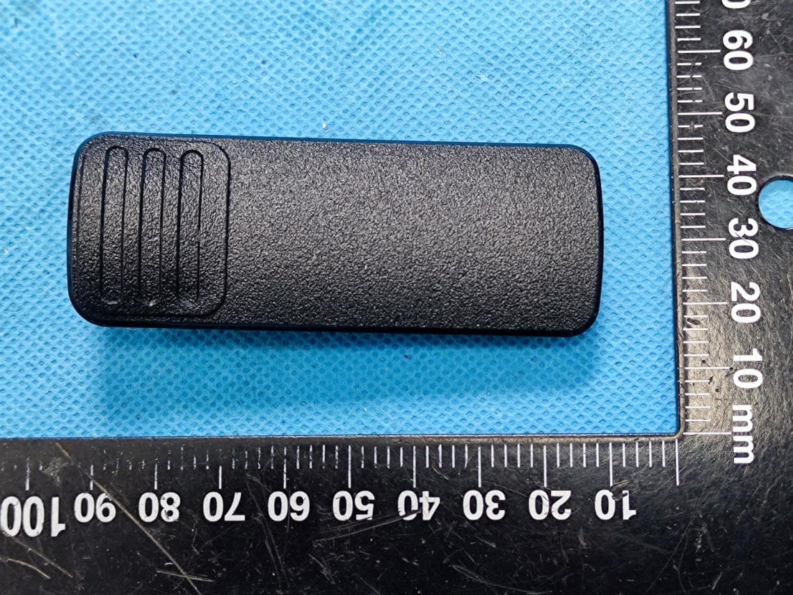
EXHIBIT B - EUT EXTERNAL PHOTOGRAPHS Antenna
Internal Photos
EXHIBIT C - EUT INTERNAL PHOTOGRAPHS Ant
Test Report
FCC PART 15.247 TEST REPORT For Hytera Communications Corporation Limited Hytera Tower, Hi-Tech Industrial Park North, 9108# Beihuan Road, Nanshan District, Shenzhen, 518057 China Report Type: Original Report Product Type: Digital Portable Radio Re port Number: RDG191217004-00C Re port Date: 2020-01-22 Reviewed By: Ivan Cao Assistant Manager Test Laboratory: Bay Area Compliance Laboratories Corp. (Dongguan) No.69 Pulongcun, Puxinhu Industry Area, Tangxia, Dongguan, Guangdong, China Tel: +86-769-86858888 Fax: +86-769-86858891 www.baclcorp.com.cn FCC ID:YAMHP68XUM Bay Area Compliance Laboratories Corp. (Dongguan) Report No.: RDG191217004-00C Page 2 of 33 TABLE OF CONTENTS GENERAL INFORMATION ....................................................................................................................................... 4 PRODUCT DESCRIPTION FOR EQUIPMENT UNDER TEST (EUT) ..................................................................................... 4 OBJECTIVE ................................................................................................................................................................... 4 RELATED SUBMITTAL(S)/GRANT(S) ............................................................................................................................. 4 TEST METHODOLOGY .................................................................................................................................................. 4 MEASUREMENT UNCERTAINTY .................................................................................................................................... 5 TEST FACILITY ............................................................................................................................................................. 5 DECLARATIONS ............................................................................................................................................................ 5 SYSTEM TEST CONFIGURATION .......................................................................................................................... 6 DESCRIPTION OF TEST CONFIGURATION ...................................................................................................................... 6 EUT EXERCISE SOFTWARE .......................................................................................................................................... 6 EQUIPMENT MODIFICATIONS ....................................................................................................................................... 7 SUPPORT CABLE LIST AND DETAILS ............................................................................................................................ 7 BLOCK DIAGRAM OF TEST SETUP ................................................................................................................................ 8 SUMMARY OF TEST RESULTS ............................................................................................................................... 9 FCC §15.247 (i) & §1.1310 & §2.1093- RF Exposure ............................................................................................... 10 APPLICABLE STANDARD ............................................................................................................................................ 10 FCC §15.203 - ANTENNA REQUIREMENT ........................................................................................................... 11 APPLICABLE STANDARD ............................................................................................................................................ 11 ANTENNA CONNECTOR CONSTRUCTION .................................................................................................................... 11 FCC §15.207 (a) – AC LINE CONDUCTED EMISSIONS ..................................................................................... 12 APPLICABLE STANDARD ............................................................................................................................................ 12 EUT SETUP ................................................................................................................................................................ 12 EMI TEST RECEIVER SETUP ....................................................................................................................................... 12 TEST PROCEDURE ...................................................................................................................................................... 12 CORRECTED AMPLITUDE & MARGIN CALCULATION ................................................................................................. 13 TEST EQUIPMENT LIST AND DETAILS ......................................................................................................................... 13 TEST DATA ................................................................................................................................................................ 13 FCC §15.209, §15.205 & §15.247(d) - SPURIOUS EMISSIONS ............................................................................. 16 APPLICABLE STANDARD ............................................................................................................................................ 16 EUT SETUP ................................................................................................................................................................ 16 EMI TEST RECEIVER & SPECTRUM ANALYZER SETUP .............................................................................................. 17 TEST PROCEDURE ...................................................................................................................................................... 17 CORRECTED AMPLITUDE & MARGIN CALCULATION .........................................…
Text truncated - open the document above for the full version.
Test Setup Photos
EXHIBIT D - TEST SETUP PHOTOGRAPHS Conducted Emissions Front View Conducted Emissions Side View Radiated Emission Below 1GHz View Radiated Emission Above 1GHz View
Contact Information
Applicant
Ruifen Huang(Certification Engineer)
Test Firm
Bay Area Compliance Laboratories Corp.(Dongguan)David Zhang
[email protected]0086 0769 86858888
Technical Specifications
| # | Rule Parts | Frequency Range | Power Output |
|---|---|---|---|
| 1 | 15C | 2.40 GHz - 2.48 GHz | 2.00 mW |
Other Applications from Hytera Communications Corporation Limited
YAMBP516LF
Aug 15, 2022Digital Portable Radio
Equipment Class
FRF - Part 95 Family Radio Face Held Transmitter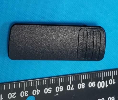
YAMBP5XXVHF
Mar 01, 2022Digital Portable Radio
Equipment Class
DSS - Part 15 Spread Spectrum Transmitter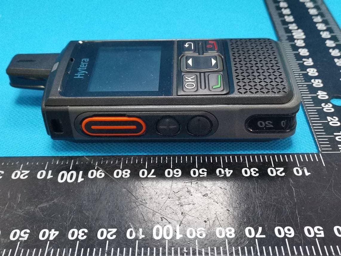
YAMPNC360S
Jan 19, 2022PoC Radio
Equipment Class
DTS - Digital Transmission System
YAMHM78XUVS
Jul 28, 2021DIGITAL MOBILE RADIO
Equipment Class
TNB - Licensed Non-Broadcast Station Transmitter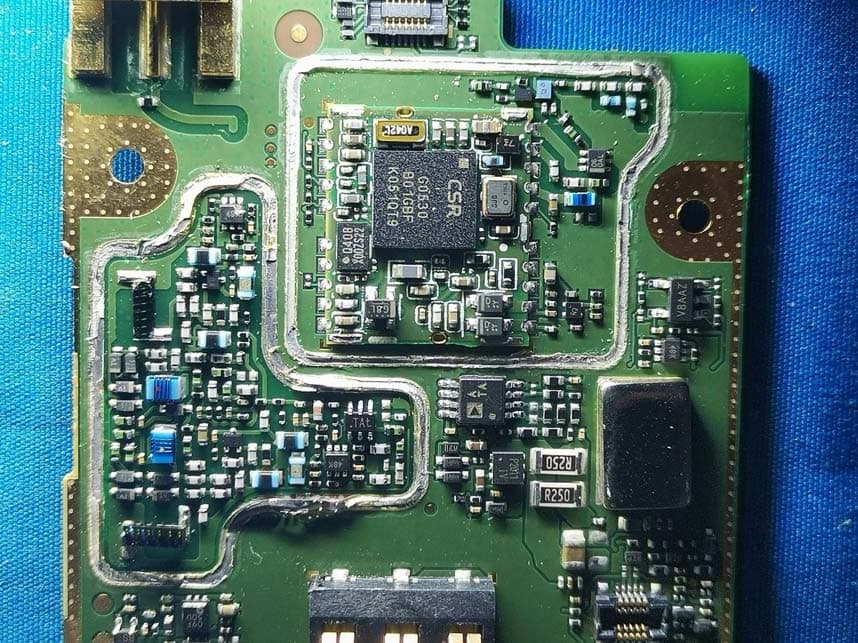
YAMHP6XXUMS
Jul 22, 2021Digital Portable Radio
Equipment Class
DTS - Digital Transmission System