YAMPD79XEXVHFEx Digital Radio
Hytera Communications Corporation Limited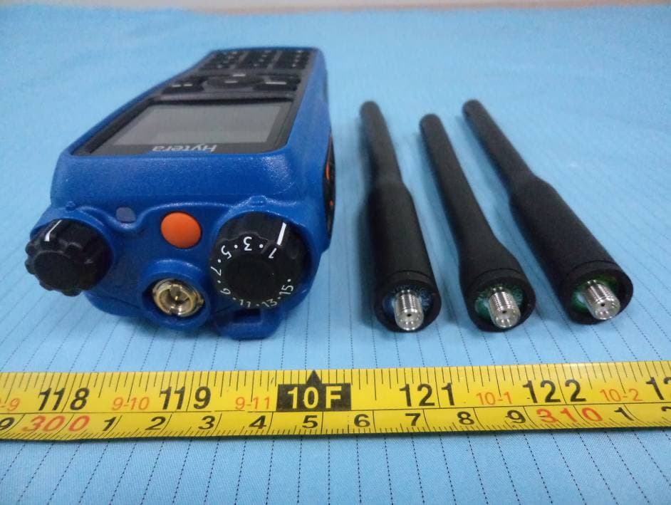
Click to zoom
Application Details
- Equipment Class
- TNF - Licensed Non-Broadcast Transmitter Held to Face
- Date of Grant
- Dec 26, 2012
- Application Purpose
- Original Equipment
- Date of Application
- Dec 26, 2012
- Equipment Note
- Ex Digital Radio
- Frequency Range
- 136.00000000 - 174.00000000
- Country
- China
Documents & Files
Document Text
Text extracted from the exhibit documents filed with the FCC. Open a document above to read the original.
Users Manual
Preface Thanks for your favor in our product. To derive optimum performance from the product, please read this manual and the supplied Safety Information Booklet carefully before use. This manual is applicable to the following model: PD79X Ex (X may indicate 2, 5, 6 or 8) 1 Instructional Icons The following icons are available through this manual: Alert Icons Caution: indicates situations that could cause damage to your product. Note: indicates tips that can help you make better use of your product. Function Icons : indicates functions that are available on digital channel only. : indicates functions that are available on analog channel only. Functions marked with no function icons are available on both analog and digital channels. Term Explanation Key Operation z Short press: to press a key and release it quickly. z Long press: to press a key and remain holding it down for a predefined period (2 seconds by default). z Hold down: to press a key and remain holding it down. Private Call Private Call is a call initiated by a single user to another user. Group Call Group Call is a call initiated by a single user to a group. All Call All Call is a call initiated by a single user to all the other users on a channel. Squelch This technology can remove excessive background noises, improving your communication quality. PTT ID PTT ID, namely radio identity, allows a radio with display or the control center to identify the calling party. 2 Copyright Information Hytera is the trademark or registered trademark of Hytera Communications Co., Ltd. (the Company) in PRC and/or other countries or areas. The Company retains the ownership of its trademarks and product names. All other trademarks and/or product names that may be used in this manual are properties of their respective owners. The product described in this manual may include the Company’s computer programs stored in memory or other media. Laws in PRC and/or other countries or areas protect the exclusive rights of the Company with respect to its computer programs. The purchase of this product shall not be deemed to grant, either directly or by implication, any rights to the purchaser regarding the Company’s computer programs. Any of the Company’s computer programs may not be copied, modified, distributed, decompiled, or reverse-engineered in any manner without the prior written consent of the Company. The AMBE+2 TM voice coding technology embodied in this product is protected by intellectual property rights including patent rights, copyrights and trade secrets of Digital Voice Systems, Inc. This voice coding technology is licensed solely for use within this product. The user of this technology is explicitly prohibited from attempting to decompile, reverse engineer, or disassemble the Object Code or in any other way convert the Object Code into a human readable form. U.S. Patent Nos. #6,912,495 B2, #6,199,037 B1, #5,870,405, #5,826,222, #5,754,974, #5,701,390, #5,715,365, #5,649,050, #5,630,011, #5,581,656, #5,517,511, #5,491,772, #5,247,579, #5,226,084 and #5,195,166. Disclaimer The Company endeavors to achieve the accuracy and completeness of this manual, but no warranty of accuracy or reliability is given. All the specifications and designs are subject to change without notice due to continuous technology development. No part of this manual may be copied, modified, translated, or distributed in any manner without the express written permission of us. If you have any suggestions or would like to learn more details, please visit our website at: http://www.hytera.com . 3 RF ENERGY EXPOSURE AWARENESS AND CONTROL INFORMATION, AND OPERATIONAL INSTRUCTIONS FOR FCC OCCUPATIONAL USE REQUIREMENTS BEFORE USING YOUR PORTABLE 2-WAY RADIO, READ THIS IMPORTANT RF ENERGY AWARENESS AND CONTROL INFORMATION AND OPERATIONAL INSTRUCTIONS TO ENSURE COMPLIANCE WITH THE FCC’S RF EXPOSURE GUIDELINES NOTICE: This radio is intended for use in occupational/controlled conditions, where users have full knowledge of their exposure and can exercise control over their exposure to meet FCC limits. This radio device is NOT authorized for general population, consumer, or any other use. This 2-way radio uses electromagnetic energy in the radio frequency (RF) spectrum to provide communications between two or more users over a distance. It uses radio frequency (RF) energy or radio waves to send and receive calls. RF energy is one form of electromagnetic energy. Other forms include, but are not limited to, electric power, sunlight and x-rays. RF energy, however, should not be confused with these other forms of electromagnetic energy, which when used improperly can cause biological damage. Very high levels of x-rays, for example, can damage tissues and genetic material. Experts in science, engineering, medicine, health and industry work with organizations to develop standards for exposure to RF energy. These standards provide recommended levels of RF exposure for both workers and the general public. These recommended RF exposure levels include substantial margins of protection. All 2-way radios marketed in North America are designed, manufactured and tested to ensure they meet government established RF exposure levels. In addition, manufacturers also recommend specific operating instructions to users of 2-way radios. These instructions are important because they inform users about RF energy exposure and provide simple procedures on how to control it. Please refer to the following websites for more information on what RF energy exposure is and how to control your exposure to assure compliance with established RF exposure limits. http://www.fcc.gov/oet/rfsafety/rf-faqs.html http://www.osha.gov/SLTC/radiofrequencyradiation/index.html Federal Communications Commission Regulations The FCC rules require manufacturers to comply with the FCC RF energy exposure limits for portable 2-way radios before they can be marketed in the U.S. When 2-way radios are used as a consequence of employment, th…
Text truncated - open the document above for the full version.
Cover Letter(s)
Hytera Communications Corporation Ltd. Add: HYT Tower, Hi-Tech Industrial Park North, Nanshan District, Shenzhen China. 518057 Tel: +86-0755-26972999 Fax: +86-755-86137130 FCC Authorization Date: 2012-9-20 FEDERAL COMMUNICATIONS COMMISSIONS Authorization and Evaluation Division 7435 Oakland Mills Road Columbia, MD 21046 Subject: Agent Authorization To whom it may concern: We, Hytera Communications Corporation Ltd., the undersigned, Hereby authorizes Bay Area Compliance Laboratories Corporation to act on its behalf in all matters relating to application for Equipment authorization, including the signing of all documents relating to these matters. All acts carried out by Bay Area Compliance Laboratories Corp. our behalf shall have the same effect as our own action. We, the undersigned, hereby certify that we are not subject to a denial of federal benefits, that includes FCC benefits, pursuant to Section 5301 of the Anti-Drug Abuse Act of 1988, 21 U.S.C. 853(a). This authorization is valid until further written notice from the applicant. Sincerely Yours, Lei Xiong General Director
Cover Letter(s)
Hytera Communications Corporation Ltd. Add: HYT Tower, Hi-Tech Industrial Park North, Nanshan District, Shenzhen China. 518057 Tel: +86-0755-26972999 Fax: +86-755-86137130 FCC Confidential Authorization Date: 2012-9-20 FEDERAL COMMUNICATIONS COMMISSIONS Authorization and Evaluation Division 7435 Oakland Mills Road Columbia, MD 21046 Confidentiality Request regarding application for certification of FCC ID: YAMPD79XEXV HF Pursuant to Sections 0.457 and 0.459 of the Commission’s Rules, we hereby request confidential treatment of information accompanying this application as outlined below: Detailed Circuit Schematics of EUT--- (Long term) Block Diagram--- (Long term) Circuit Description--- (Long term) Part List--- (Long term) Turn up procedure--- (Long term) The above materials contain trade secrets and proprietary information not customarily released to the public. The public disclosure of these materials may be harmful to the applicant and provide unjustified benefits to its competitors. The applicant understands that pursuant to Section 0.457 of the Rules, disclosure of this application and all accompanying documentation will not be made before the date of the Grant for this application. Sincerely Yours, Lei Xiong General Director
Cover Letter(s)
Hytera Communications Corporation Ltd. Add: HYT Tower, Hi-Tech Industrial Park North, Nanshan District, Shenzhen China. 518057 Tel:+86-0755-26972999 Fax: +86-0755-86137130 Justification Letter DATE: 2012-4-5 FEDERAL COMMUNICATIONS COMMISSIONS Authorization and Evaluation Division 7435 Oakland Mills Road Columbia, MD 21046 FCC ID: YAMX1EVHF Model number: X1e VHF To whom it may concern: We, Hytera Communications Corporation Ltd., acknowledge that this device will not be marketed to USA users with the frequency band which is not allowed by rule part 90.and it is a violation of FCC rules if this device is operated on unauthorized frequencies inside the U.S.A. We, Hytera Communications Corporation Ltd., acknowledge this equipment meets the requirements of FCC Rules, Parts 90.203 (e) and (g) as applicable. Programming of this product's transmit frequencies can be performed ONLY by the manufacturer or by service or maintenance personnel. The operator cannot program transmit frequencies using the equipment's external operation. Client’s signature: Lei Xiong General Director DATE: 2012-09-10 FCC ID: YAMTC-508 Model number: TC-508V FCC ID: YAMTC-508V DATE: 2012-09-20 FCC ID: YAMPD79XEXVHF Model number: PD79X Ex VHF
External Photos
EXHIBIT B - EUT EXTERNAL PHOTOGRAPHS EUT – Front View EUT – Rear View EUT – Top with Antenna View EUT – Bottom View EUT – Left Side View EUT – Right Side View EUT – Antenna View
ID Label/Location Info
EXHIBIT A - FCC ID LABELING AND LOCATION FCC ID Label FCC ID Label Location The label shown shall be permanently affixed at a conspicuous location on the device and be readily visible to the user at the time purchase (Labeling requirements per 2.925) Label Here
Internal Photos
EXHIBIT C - EUT INTERNAL PHOTOGRAPHS EUT – Battery off View EUT – Cover off View 1 EUT – Cover off View 2 EUT – Main Board Top View EUT – Main Board Top Shielding off View EUT – Main Board Bottom View EUT – Main Board Bottom Shielding off View EUT – Display Board Top View EUT – Display Board Bottom View
RF Exposure Info
Bay Area Compliance Laboratories Corp. (Shenzhen) Report No.: R1DG120904005-00 FCC Part 90 Page 8 of 37 FCC §1.1307(b) & §2.1093 - RF EXPOSURE Applicable Standard According to FCC §2.1093 and §1.1307(b) (1), systems operating under the provisions of this section shall be operated in a manner that ensure that the public is not exposed to radio frequency energy level in excess of the Commission’s guideline. According to FCC KDB 447498 D01 Mobile Portable RF Exposure v04 section 5, Push-to-talk (PTT) devices: a) RF exposure is evaluated with a duty factor of 50% when the actual operating duty factor is ≤ 50%. Devices supporting higher duty factors shall be evaluated at the maximum duty factor; for example, devices supporting operator-assisted PSTN calls. Contact the FCC Laboratory when unable to test a device at the required duty factor due to hardware limitations or other reasons. b) Portable PTT devices i) The power thresholds and operating conditions in Table 1 are used to determine SAR test requirements for PTT radios required to comply with the general population exposure limit. When the occupational exposure limit applies, these power thresholds are increased by a factor of five (5) to determine the test requirements. SAR is required for PTT devices with maximum output power greater than these thresholds.28 SAR evaluation is also required for separation distances smaller than those in Table 1. Contact the FCC Laboratory to determine if SAR evaluation is necessary for other frequencies or when the SAR is very low. SAR Evaluation Power Thresholds for PTT devices,f≤0.5GHz Exposure Conditions mW (for uncontrolled) mW (for occupational) Held to face ≥2.5cm 250 1250 Body-worn ≥1.5cm 200 1000 Body-worn ≥1.0cm 150 750 ii) Additional SAR evaluation with a SAM phantom is required for PTT devices with held-to-ear operating mode.29 Contact the FCC Laboratory for device operating and test configurations. Routine SAR evaluation refers to that specifically required by §2.1093, using measurements or computer simulation. When routine SAR evaluation is not required, portable transmitters with output power greater than the applicable low threshold require SAR evaluation to qualify for TCB approval. Bay Area Compliance Laboratories Corp. (Shenzhen) Report No.: R1DG120904005-00 FCC Part 90 Page 9 of 37 Result: 1. The distance between the antenna and the users is 2.3cm for boby worn,and 2.5cm for face 2. The output power: Mode Frequency (MHz) Peak Output Power (dBm) Average Output Power (mW) Duty Cycle (%) Average Output Power (mW) Comments 136.5 30.00 1000 50.00 500 High Power 138.5 30.00 1000 50.00 500 High Power 146.5 30.40 1096 50.00 603 High Power 147.5 30.45 1109 50.00 616 High Power 155.5 30.24 1057 50.00 560 High Power 159.5 30.53 1130 50.00 638 High Power 160.5 30.52 1127 50.00 637 High Power 167.5 30.36 1086 50.00 592 High Power Analog Modulation (FM) 173.5 30.07 1016 50.00 518 High Power 136.5 30.01 1002 49.68 498 High Power 138.5 30.01 1002 49.68 498 High Power 146.5 30.43 1104 49.68 603 High Power 147.5 30.49 1119 49.68 623 High Power 155.5 30.25 1059 49.68 558 High Power 159.5 30.57 1140 49.68 646 High Power 160.5 30.57 1140 49.68 646 High Power 167.5 30.39 1094 49.68 592 High Power Digital Modulation (4FSK) 173.5 30.08 1019 49.68 516 High Power Bay Area Compliance Laboratories Corp. (Shenzhen) Report No.: R1DG120904005-00 FCC Part 90 Page 10 of 37 Note: duty cycle=Ton/Tp=29.8ms/60ms=0.4968 (49.68%) for 4FSK modulation, worst case at data transmiting mode Conclusion: The maximum time-averaged output power is 646 mW <the exclusion thresholds is 1000 mW According to FCC KDB 447498 D01 Mobile Portable RF Exposure v04 section 5, Push-to-talk (PTT) devices, the SAR evaluation is not required. Offset 10 dB B LVL PS 3DB RBW 100 kHz VBW 300 kHz AC Att 40 dB * Ref 35 dBm 1 AP CLRWR Center 156 MHz20 ms/ SWT 200 ms SGL -60 -50 -40 -30 -20 -10 0 10 20 30 Date: 21.DEC.2012 18:52:09 Offset 10 dB B LVL PS 3DB RBW 100 kHz VBW 300 kHz AC Att 40 dB * Ref 35 dBm Center 156 MHz10 ms/ SWT 100 ms SGL 1 AP CLRWR -60 -50 -40 -30 -20 -10 0 10 20 30 1 Marker 1 [T1 ] -39.25 dBm 27.800000 ms 2 Delta 2 [T1 ] 8.91 dB 29.800000 ms 1 Delta 1 [T1 ] 3.38 dB 60.000000 ms Date: 21.DEC.2012 18:53:16
Test Report
Note: This test report is prepared for the customer shown above and for the equipment described herein. It may not be duplicated or used in part without prior written consent from Bay Area Compliance Laboratories Corp. This report must not be used by the customer to claim product certification, approval, or endorsement by NVLAP*, NIST, or any agency of the Federal Government. * This report may contain data that are not covered by the NVLAP accreditation and shall be marked with an asterisk “★” FCC PART 90 TEST REPORT For Hytera Communications Corporation Ltd. HYT Tower, Hi-Tech Industrial Park North, Nanshan District, Shenzhen, Guangdong, China FCC ID: YAMPD79XEXVHF Report Type: Original Report Product Type: Ex Digital Radio Test Engineer: Eric Lee Report Number: R1DG120904005-00 Report Date: 2012-12-27 Reviewed By: Alvin Huang RF Leader Test Laboratory: Bay Area Compliance Laboratories Corp. (Shenzhen) 6/F, the 3rd Phase of WanLi Industrial Building ShiHua Road, FuTian Free Trade Zone Shenzhen, Guangdong, China Tel: +86-755-33320018 Fax: +86-755-33320008 www.baclcorp.com.cn Bay Area Compliance Laboratories Corp. (Shenzhen) Report No.: R1DG120904005-00 FCC Part 90 Page 2 of 37 TABLE OF CONTENTS GENERAL INFORMATION.......................................................................................................................................4 PRODUCT DESCRIPTION FOR EQUIPMENT UNDER TEST (EUT) .....................................................................................4 OBJECTIVE...................................................................................................................................................................4 RELATED SUBMITTAL(S)/GRANT(S).............................................................................................................................4 TEST METHODOLOGY..................................................................................................................................................4 TEST FACILITY.............................................................................................................................................................4 SYSTEM TEST CONFIGURATION ..........................................................................................................................6 DESCRIPTION OF TEST CONFIGURATION......................................................................................................................6 EQUIPMENT MODIFICATIONS.......................................................................................................................................6 BLOCK DIAGRAM OF TEST SETUP................................................................................................................................6 SUMMARY OF TEST RESULTS...............................................................................................................................7 FCC §1.1307(b) & §2.1093 - RF EXPOSURE.............................................................................................................8 APPLICABLE STANDARD..............................................................................................................................................8 FCC §2.1046 & §90.205- RF OUTPUT POWER......................................................................................................11 APPLICABLE STANDARD............................................................................................................................................11 TEST PROCEDURE......................................................................................................................................................11 TEST EQUIPMENT LIST AND DETAILS.........................................................................................................................11 TEST DATA................................................................................................................................................................11 FCC §2.1047 & §90.207 - MODULATION CHARACTERISTIC ..........................................................................14 APPLICABLE STANDARD............................................................................................................................................14 TEST PROCEDURE......................................................................................................................................................14 TEST EQUIPMENT LIST AND DETAILS.........................................................................................................................14 TEST DATA................................................................................................................................................................14 FCC §2.1049, §90.209 & §90.210 – OCCUPIED BANDWIDTH & EMISSION MASK......................................20 APPLICABLE STANDARD............................................................................................................................................20 TEST PROCEDURE......................................................................................................................................................20 TEST EQUIPMENT LIST AND DETAILS.........................................................................................................................21 TEST DATA................................................................................................................................................................21 FCC §2.1051 & §90.210 - SPURIOUS EMISSIONS AT ANTENNA TERMINALS ............................................25 APPLICABLE STANDARD............................................................................................................................................25 TEST PROCEDURE.............................................................................................................…
Text truncated - open the document above for the full version.
Test Setup Photos
EXHIBIT D - TEST SETUP PHOTOGRAPHS Radiated Emissions View Extreme Condition View
Contact Information
Applicant
Ruifen Huang(Certification Engineer)
Test Firm
Bay Area Compliance Laboratory Corp. (Shenzhen)John Chan
Technical Specifications
| # | Rule Parts | Frequency Range | Power Output | Emission | Tolerance |
|---|---|---|---|---|---|
| 2 | 9 | 136 MHz - 174 MHz | 1.14 W | 7K40FXD | 0.23 ppm |
Other Applications from Hytera Communications Corporation Limited
YAMBP516LF
Aug 15, 2022Digital Portable Radio
Equipment Class
FRF - Part 95 Family Radio Face Held Transmitter
YAMBP5XXVHF
Mar 01, 2022Digital Portable Radio
Equipment Class
DSS - Part 15 Spread Spectrum Transmitter
YAMPNC360S
Jan 19, 2022PoC Radio
Equipment Class
DTS - Digital Transmission System
YAMHM78XUVS
Jul 28, 2021DIGITAL MOBILE RADIO
Equipment Class
TNB - Licensed Non-Broadcast Station Transmitter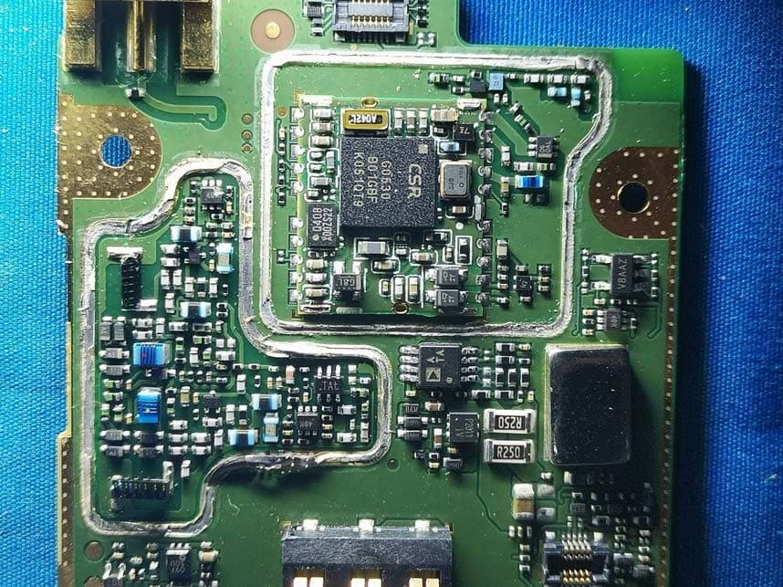
YAMHP6XXUMS
Jul 22, 2021Digital Portable Radio
Equipment Class
DTS - Digital Transmission System