YAMPOA47Wireless PTT
Hytera Communications Corporation Limited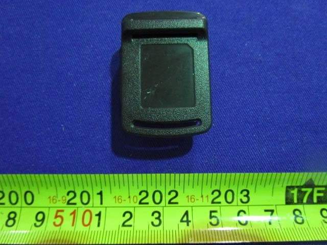
Click to zoom
Application Details
- Equipment Class
- DSS - Part 15 Spread Spectrum Transmitter
- Date of Grant
- Nov 10, 2015
- Application Purpose
- Original Equipment
- Date of Application
- Nov 10, 2015
- Equipment Note
- Wireless PTT
- Frequency Range
- 2402.00000000 - 2480.00000000
- Country
- China
Documents & Files
Document Text
Text extracted from the exhibit documents filed with the FCC. Open a document above to read the original.
Users Manual
1 Preface Thanks for your favor in our product. To derive optimum performance from the product, please read this manual carefully before use. This manual is applicable to the following product: SM15W0 Wireless Remote Speaker Microphone POA47 Wireless Finger PTT Instructional Icons The following icons are available through this manual: IconDescription Note Indicates references that can further describe the related topics. Caution Indicates situations that could cause data loss or equipment damage. Notational Conventions ItemDescription “ ” T h e q u o t a t i o n m a r k s e n c l o s e t h e n a m e o f a software interface element. For example, click “OK”. 【 】 T h e t e x t i n b o l d f a c e d e n o t e s t h e n a m e o f a hardware button. For example, press the PTT key. Key Operation Operation OptionDefinition Short press P r e s s t h e k e y a n d r e l e a s e w i t h i n 1 second. Long press Press the key and hold it for no less than 2 seconds. 2 Copyright Information HYT and Hytera are the trademarks or registered trademarks of Hytera Communications Co., Ltd. (the Company) in PRC and/or other countries or areas. The Company retains the ownership of its trademarks and product names. All other trademarks and/or product names that may be used in this manual are properties of their respective owners. T h e p r o d u c t d e s c r i b e s i n t h i s m a n u a l m a y i n c l u d e t h e Company’s computer programs stored in memory or other media. Laws in PRC and/or other countries or areas protect the exclusive rights of the Company with respect to its computer programs. The purchase of this product shall not be deemed to grant, either directly or by implication, any rights to the purchaser regarding the Company’s computer programs. Any of the Company’s computer programs may not be copied, modified, distributed, decompiled, or reverse-engineered in any manner without the prior written consent of the Company. Disclaimer T h e C o m p a n y e n d e a v o r s t o a c h i e v e t h e a c c u r a c y a n d completeness of this manual, but no warranty of accuracy or reliability is given. All the specifications and designs are subject to change without notice due to continuous technology development. No part of this manual may be copied, modified, translated, or distributed in any manner without the express written permission of us. We do not guarantee, for any particular purpose, the accuracy, validity, timeliness, legitimacy or completeness of the Third Party products and contents involved in this manual. 23 If you have any suggestions or would like to learn more details, please visit our website at: http://www.hytera.com Safety and Maintenance To help you ward off bodily injury and property loss resulting from improper operation, please read the following safety information carefully before use. The product is in compliance with IP54 requirements. To have a good waterproof performance, please keep the charge jack covered when the device is not charging. Please operate the product within the temperature range of -10 ~ 50 °C . Make sure the adapter plugs are in good condition, or it will cause damage to the product or your bodily safety. Do not drop, knock, or shake the device. Rough handling can set the device in function failure state. Do not repair the product without authorization. Use a non-woven cloth with neutral cleanser to clean the keys and housing after long-time use. Do not use stain removers, alcohol, sprays or oil preparations. Make sure the products are completely dry before use. Caution:Please turn off the product before cleaning. Wireless Remote Speaker Microphone Checking Items in the Package Please unpack carefully and check that all items listed below are received. If any item is missing or damaged, please contact your local dealer. 10 Wireless Finger PTT Checking Items in the Package Please unpack carefully and check that all items listed below are received. If any item is missing or damaged, please contact your local dealer. Product Introduction Product Controls No.Part NameNo.Part Name 1- Key2LED Indicator 3PTT (Push-to-Talk) Key 4+ Key 5Charge Jack// Wireless PTT Velcro Power Adapter Documentation Kit 1 2 3 4 5 Owner's Manual 1011 Note: You can transmit audio signals by holding down PTT key. You can press +/ - key to adjust the volume or change the channel. It should be noted the specific function of the +/ - key is depending on the paired radio. LED Indicator LED IndicationProduct Status Blue Flashes for 4 times continuously Powering on Glows solidly Pairing Flashes slowly (once every 3 seconds) No connection Flashes twice in a row every three minutes Connected with the radio but unable to transmit audio signals Flashes quickly (once per second) Connected with the radio and able to transmit audio signals Red Flashes for 4 times continuously Powering off Flashes slowly (once every 3 seconds) Low battery Flashes quickly (once per second) Charging Glows solidly Transmitting GreenGlows solidly Fully charged Before Use Charging the Battery Please charge the battery before use in the way shown below: 1. Uncover the charge jack. 12 1 2 1 2 3 2. Use the power adapter to connect the product with the AC power socket as the diagram instructs. Diagram for charging Upon charging, the product will power off automatically and the LED indicator will glow red. Note: Please turn off the product and get it fully charged before it stands idle for a long time. Please charge the product every three months, or the life span of the battery would be shortened. If the product is idle for over three months, its LED indicator only turns red after it has been charged for 10 to 20 minutes. Assembling and Wearing the Wireless Finger PTT Please assemble the wireless PTT and Velcro in the way shown below: 1213 4 5 6 Basic Operations Turning On/Off the Product To turn on the product, long press the Power On/Off key until the LED indicator flashes blue. To turn off the p…
Text truncated - open the document above for the full version.
Cover Letter(s)
QA-FR-171-A Hytera Communications Corporation Ltd. Add: HYT Tower, Hi-Tech Industrial Park North, Nanshan District, Shenzhen China. 518057 Tel: +86-0755-26972999 Fax: +86-0755-86137130 FCC Confidential Authorization 2015-10-10 FEDERAL COMMUNICATIONS COMMISSIONS Authorization and Evaluation Division 7435 Oakland Mills Road Columbia, MD 21046 Subject: Confidentiality Request regarding application for certification of FCC ID: YAMPOA47 In accordance with Sections 0.457 and 0.459 of the Commission’s Rules, Hytera Communications Corporation Ltd.. Wireless Inc. hereby requests long-term confidential treatment of information accompanying this application as outlined below: • Block Diagram • Schematics • Operation Description The above materials contain proprietary and confidential information not customarily released to the public. The public disclosure of these materials provides unjustified benefits to its competitors in the market. Sincerely, Client’s signature Client’s name/ title Lei Xiong General Director
External Photos
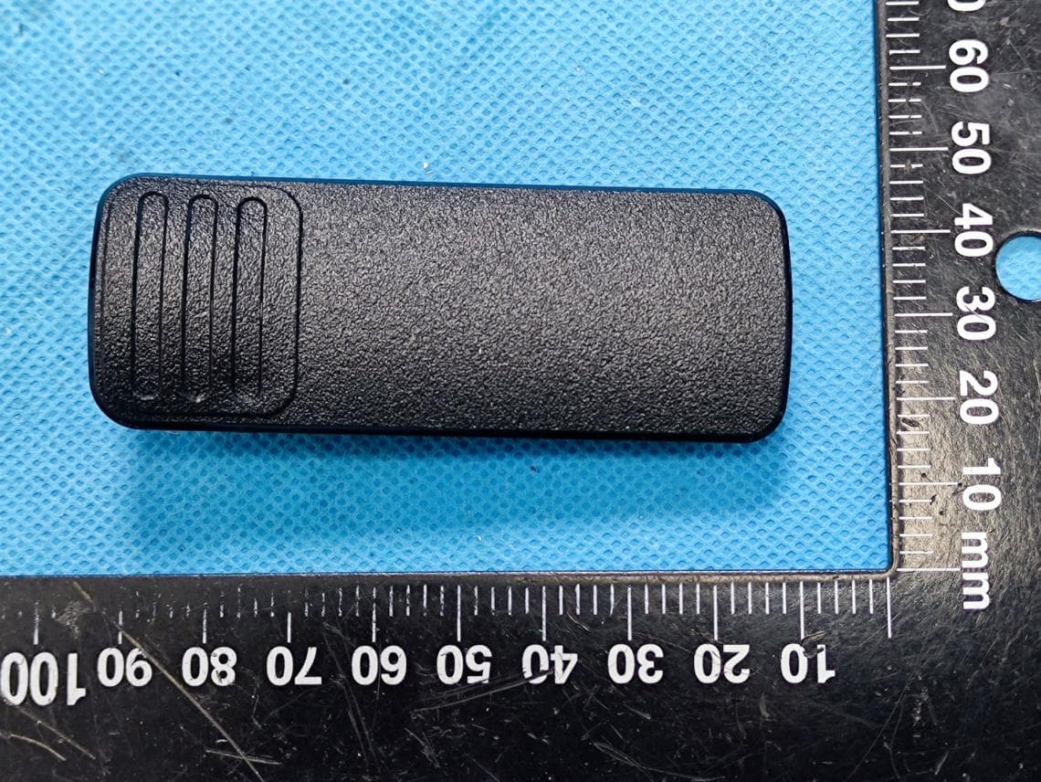
EXHIBIT B - EUT EXTERNAL PHOTOGRAPHS EUT – All View EUT –Top View EUT –Bottom View EUT – Side View EUT –Side View EUT – Label View
ID Label/Location Info
EXHIBIT A - FCC ID LABELING AND LOCATION FCC ID Label Proposed FCC ID Label Location The label shown shall be permanently affixed at a conspicuous location on the device and be readily visible to the user at the time purchase (Labeling requirements per 2.925) Label Here
Internal Photos
EXHIBIT C - EUT INTERNAL PHOTOGRAPHS EUT –Uncover View EUT –Main Board Top View EUT –Main Board Bottom View EUT –Main Board Bottom Uncover View EUT –BT Chip View EUT –Ant View EUT –Battery Top View EUT –Battery Bottom View
Test Report
Note: This test report is prepared for the customer shown above and for the device described herein. It may not be duplicated or used in part without prior written consent from Bay Area Compliance Laboratories Corp. (Dongguan). This report is valid only with a valid digital signature. The digital signature may be available only under the Adobe software above version 7.0. FCC PART 15.247 TEST REPORT For Hytera Communications Co.,Ltd. HYT Tower, Hi-Tech Industrial Park North, Nanshan District, Shenzhen, China Report Type: Original Report Product Type: Wireless PTT Test En gineer: Allen Qiao Report Number: RDG150929001-00 Re port Date: 2015-10-10 Reviewed B y: Sula Huang RF Leader Test Laboratory: Bay Area Compliance Laboratories Corp. (Dongguan) No.69 Pulongcun, Puxinhu Industrial Zone, Tangxia, Dongguan, Guangdong, China Tel: +86-769-86858888 Fax: +86-769-86858891 www.baclcorp.com.cn FCC ID: YAMPOA47 Bay Area Compliance Laboratories Corp. (Dongguan) Report No.: RDG150929001-00 FCC Part 15.247 Page 2 of 67 TABLE OF CONTENTS GENERAL INFORMATION ....................................................................................................................................... 4 PRODUCT DESCRIPTION FOR EQUIPMENT UNDER TEST (EUT) ..................................................................................... 4 OBJECTIVE ................................................................................................................................................................... 4 RELATED SUBMITTAL(S)/GRANT(S) ............................................................................................................................. 4 TEST METHODOLOGY .................................................................................................................................................. 4 TEST FACILITY ............................................................................................................................................................. 4 SYSTEM TEST CONFIGURATION .......................................................................................................................... 5 DESCRIPTION OF TEST CONFIGURATION ...................................................................................................................... 5 EUT EXERCISE SOFTWARE .......................................................................................................................................... 5 EQUIPMENT MODIFICATIONS ....................................................................................................................................... 5 LOCAL SUPPORT EQUIPMENT LIST AND DETAILS ........................................................................................................ 5 SUPPORT CABLE LIST AND DETAILS ............................................................................................................................ 5 BLOCK DIAGRAM OF TEST SETUP ................................................................................................................................ 6 SUMMARY OF TEST RESULTS ............................................................................................................................... 7 FCC §15.247 (i) & §1.1310 & §2.1093- RF EXPOSURE ............................................................................................... 8 APPLICABLE STANDARD .............................................................................................................................................. 8 FCC §15.203 - ANTENNA REQUIREMENT ............................................................................................................. 9 APPLICABLE STANDARD .............................................................................................................................................. 9 ANTENNA CONNECTOR CONSTRUCTION ...................................................................................................................... 9 FCC §15.207 (a) – AC LINE CONDUCTED EMISSIONS ..................................................................................... 10 APPLICABLE STANDARD ............................................................................................................................................ 10 MEASUREMENT UNCERTAINTY .................................................................................................................................. 10 EUT SETUP ................................................................................................................................................................ 10 EMI TEST RECEIVER SETUP ....................................................................................................................................... 11 TEST PROCEDURE ...................................................................................................................................................... 11 CORRECTED AMPLITUDE & MARGIN CALCULATION ................................................................................................. 11 TEST EQUIPMENT LIST AND DETAILS ......................................................................................................................... 12 TEST RESULTS SUMMARY .......................................................................................................................................... 12 TEST DATA ................................................................................................................................................................ 12 FCC §15.209, §15.205 & §15.247(d) - SPURIOUS EMISSIONS ............................................................................. 15 APPLICABLE STANDARD ............................................................................................................................................ 15 MEASUREMENT UNCERTAINTY ...........................................…
Text truncated - open the document above for the full version.
Test Setup Photos
EXHIBIT D - TEST SETUP PHOTOGRAPHS Conducted Emissions - Front View Conducted Emissions – Side View Radiated Emission - Below 1GHz Radiated Emission –Above 1GHz
Contact Information
Applicant
Ruifen Huang(Certification Engineer)
Test Firm
Bay Area Compliance Laboratories Corp. (Dongguan)John Chan
[email protected]86-769-86858888
Technical Specifications
| # | Rule Parts | Frequency Range | Power Output |
|---|---|---|---|
| 1 | 15C | 2.40 GHz - 2.48 GHz | 2.30 mW |
Other Applications from Hytera Communications Corporation Limited
YAMBP516LF
Aug 15, 2022Digital Portable Radio
Equipment Class
FRF - Part 95 Family Radio Face Held Transmitter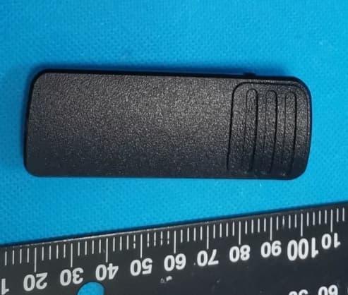
YAMBP5XXVHF
Mar 01, 2022Digital Portable Radio
Equipment Class
DSS - Part 15 Spread Spectrum Transmitter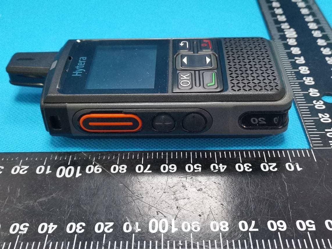
YAMPNC360S
Jan 19, 2022PoC Radio
Equipment Class
DTS - Digital Transmission System
YAMHM78XUVS
Jul 28, 2021DIGITAL MOBILE RADIO
Equipment Class
TNB - Licensed Non-Broadcast Station Transmitter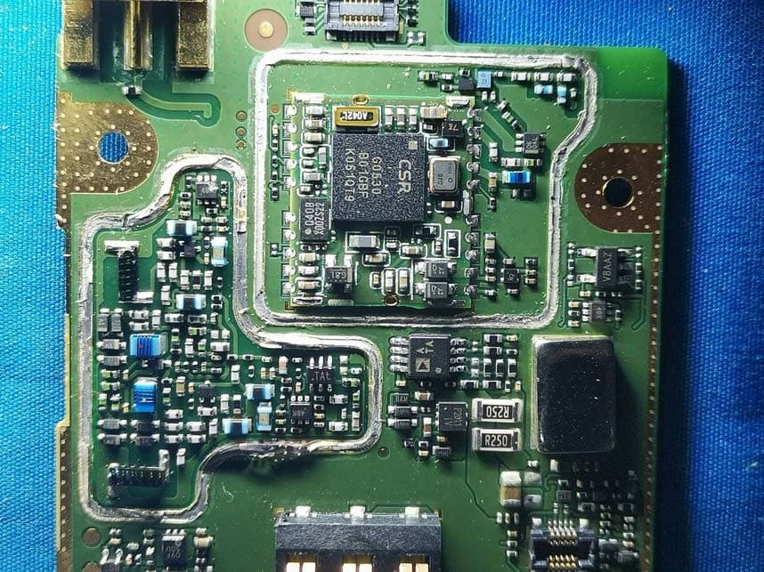
YAMHP6XXUMS
Jul 22, 2021Digital Portable Radio
Equipment Class
DTS - Digital Transmission System