YAMRD62XUHFDigital Wall-mounted Repeater
Hytera Communications Corporation Limited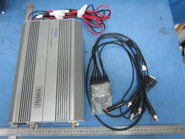
Click to zoom
Application Details
- Equipment Class
- TNB - Licensed Non-Broadcast Station Transmitter
- Date of Grant
- Feb 11, 2015
- Application Purpose
- Original Equipment
- Date of Application
- Feb 04, 2015
- Equipment Note
- Digital Wall-mounted Repeater
- Frequency Range
- 450.00000000 - 527.00000000
- Country
- China
Documents & Files
Document Text
Text extracted from the exhibit documents filed with the FCC. Open a document above to read the original.
Users Manual
Preface Thanks for your favor in our product. To derive optimum performance from the product, please read this manual and the Safety Information Booklet carefully before use. This manual is applicable to the following product: RD620 Repeater Instructional Icons Caution: Indicates situations that could cause damage to your product or bodily injury. Note: Indicates tips that can help you make better use of your product. Term Explanation Voltage Standing Wave Ratio (VSWR) Voltage Standing Wave Ratio (VSWR) is a value that measures how well a load is impedance-matched to a source. Copyright Information Hytera is the trademark or registered trademark of Hytera Communications Co., Ltd. (the Company) in PRC and/or other countries or areas. The Company retains the ownership of its trademarks and product names. All other trademarks and/or product names that may be used in this manual are properties of their respective owners. The product described in this manual may include the Company’s computer programs stored in memory or other media. Laws in PRC and/or other countries or areas protect the exclusive rights of the Company with respect to its computer programs. The purchase of this product shall not be deemed to grant, either directly or by implication, any rights to the purchaser regarding the Company’s computer programs. Any of the Company’s computer programs may not be copied, modified, distributed, decompiled, or reverse-engineered in any manner without the prior written consent of the Company. The AMBE+2TM voice coding technology embodied in this product is protected by intellectual property rights including patent rights, copyrights and trade secrets of Digital Voice Systems, Inc. This voice coding technology is licensed solely for use within this product. The user of this technology is explicitly prohibited from attempting to decompile, reverse engineer, or disassemble the Object Code or in any other way convert the Object Code into a human-readable format. U.S. Patent No: #6,912,495 B2, #6,199,037 B1, #5,870,405, #5,826,222, #5,754,974, #5,701,390, #5,715,365, #5,649,050, #5,630,011, #5,581,656, #5,517,511, #5,491,772, #5,247,579, #5,226,084 and #5,195,166. Disclaimer The Company endeavors to achieve the accuracy and completeness of this manual, but no warranty of accuracy or reliability is given. All the specifications and designs are subject to change without notice due to continuous technology development. No part of this manual may be copied, modified, translated, or distributed in any manner without the express written permission of us. We do not guarantee, for any particular purpose, the accuracy, validity, timeliness, legitimacy or completeness of the Third Party products and contents involved in this manual. If you have any suggestions or would like to learn more details, please visit our website at: http://www.hytera.com. RF Radiation Information This product must be restricted to operations in an Occupational/Controlled RF exposure Environments. Users must be fully aware of the hazards of the exposure and able to exercise control over their RF exposure to qualify for the higher exposure limits. RF Radiation Profile Radio Frequency (RF) is a frequency of electromagnetic radiation in the range at which radio signals are transmitted. RF technology is widely used in communication, medicine, food processing and other fields. It may generate radiation during use. RF Radiation Safety In order to ensure user health, experts from relevant industries including science, engineering, medicine and health work with international organizations to develop standards for safe exposure to RF radiation. These standards consist of: z United States Federal Communications Commission, Code of Federal Regulations; 47CFR part 2 sub-part J; z American National Standards Institute (ANSI)/Institute of Electrical and Electronic Engineers (IEEE) C95. 1-1992; z Institute of Electrical and Electronic Engineers (IEEE) C95.1-1999; z International Commission on Non-Ionizing Radiation Protection (ICNIRP) 1998. Contents 1. Checking Items in the Package ........................................................................................................... 1 2. Product Introduction ............................................................................................................................ 2 2.1 Parts ................................................................................................................................................. 2 2.2 Front Panel ....................................................................................................................................... 3 2.3 Rear Panel ........................................................................................................................................ 4 3. Status Indication .................................................................................................................................. 5 4. Before Use ............................................................................................................................................ 6 4.1 Instruction ......................................................................................................................................... 6 4.2 Wall-mount Bracket Installation (Optional) ........................................................................................ 6 5. Alarm Information ................................................................................................................................ 9 6. Troubleshooting ................................................................................................................................. 10 7. Care and Cleaning .............................................................................................................................. 11 8. Optional Accessories ........................................................................................…
Text truncated - open the document above for the full version.
Cover Letter(s)
Hytera Communications Co., Ltd 022311 – 6 Authority to Act as Agent Date: 2014-06-18 American Certification Body, Inc. 6731 Whittier Avenue Suite C110 McLean, VA 22101 To Whom It May Concern: Shenzhen Huatongwei International Inspection Co., Ltd / Hans Hu is authorized to act on our behalf, until otherwise notified, for applications to American Certification Body, Inc. (ACB). We certify that we are not subject to denial of federal benefits, that includes FCC benefits, pursuant to Section 5301 of the Anti-Drug Abuse Act of 1988, 21 U.S.C. 862. Further, no party, as defined in 47 CFR 1.2002 (b), to the application is subject to denial of federal benefits, that includes FCC benefits. Thank you, Agency Agreement Expiration Date: _____2015-06-01_____ By: Xiong Lei (Signature 1 ) (Print name) Title: Director of management dept On behalf of: Hytera Communications Co., Ltd (Company Name) Telephone: 86-0755 2697 2999 1 - Must be signed by applicant contact given for applicant on the FCC site, or by the authorized agent if an appropriate authorized agent letter has been provided. Letters should be placed on appropriate letterhead.
Cover Letter(s)
Hytera Communications Co., Ltd 022311 – 6 Request for Confidentiality Date: 2014-06-18 Subject: Confidentiality Request for: FCC ID: YAMRD62XUHF Pursuant to FCC 47 CRF 0.457(d) and 0.459 and IC RSP-100, Section 10, the applicant requests that a part of the subject FCC application be held confidential. Type of Confidentiality Requested Exhibit Short Term Permanent Block Diagrams Short Term External Photos Short Term Permanent* 2 Internal Photos Short Term Permanent Operation Description/Theory of Operation Short Term Permanent Parts List & Placement/BOM Short Term Permanent Tune-Up Procedure Short Term Permanent Schematics Short Term Test Setup Photos Short Term Permanent* User’s Manual *Note: ______(Insert Explanation as Necessary)______ Hytera Communications Co., Ltd has spent substantial effort in developing this product and it is one of the first of its kind in industry. Having the subject information easily available to "competition" would negate the advantage they have achieved by developing this product. Not protecting the details of the design will result in financial hardship. Permanent Confidentiality: The applicant requests the exhibits listed above as permanently confidential be permanently withheld from public review due to materials that contain trade secrets and proprietary information not customarily released to the public. Short-Term Confidentiality: The applicant requests the exhibits selected above as short term confidential be withheld from public view for a period of ___(specify number of days not to exceed 180 ) 3 ___ days from the date of the Grant of Equipment Authorization and prior to marketing. This is to avoid premature release of sensitive information prior to marketing or release of the product to the public. Applicant is also aware that they are responsible to notify ACB in the event information regarding the product or the product is made available to the public. ACB will then release the documents listed above for public disclosure pursuant to FCC Public Notice DA 04-1705. NOTE for Industry Canada Applications: The applicant understands that until such time that IC distinguishes between Short Term and Permanent Confidentiality, either type of marked exhibit above will simply be marked Confidential when submitted to IC. Sincerely, Xiong Lei By: (Signature4) (Print name) 2 - The asterisked items (*) require further justification before permanent confidentiality will be allowed. These also currently require review by the FCC under their Permit-But-Ask policy before the grant is issued and can delay completion of an application. Further justification should be added to the note above. One such example for a potted device would be: “The EUT is FULLY potted using a non-removable epoxy based material. Removal of potting material causes irreparable damage to internal circuitry. See photographs exhibits that outline the device before and after potting.” 3 - Please refer to http://acbcert.com/documents/misc-docs/Memo-Short-Term-Vs-Standard-Confidentiality.pdf for complete details. 4 - Must be signed by applicant contact given for applicant on the FCC site, or by the authorized agent if an appropriate authorized agent letter has been provided. Letters should be placed on appropriate letterhead.
Cover Letter(s)
Justification Letter DATE: May. 15, 2014 Federal Communications Commission Authorization & Evaluation Division 7435 Oakland Mills Road Colombia, Maryland 21046 FCC ID: YAMRD62XUHF Model: RD620 U(2), RD622 U(2),RD625 U(2),RD626 U(2),RD628 U(2) Dear Sir/Madam, We , Hytera Communications Corporation Ltd. acknowledge that this device will not be marketed to USA users with the frequency band which is not allowed by rule part 90.and it is a violation of FCC rules if this device is operated on unauthorised frequencies inside the U.S.A. We , Hytera Communications Corporation Ltd. acknowledge this equipment meets the requirements of FCC Rules, Parts 90.203 (e) and (g) as applicable. Programming of this product's transmit frequencies can be performed ONLY by the manufacturer or by service or maintenance personnel. The operator cannot program transmit frequencies using the equipment's external operation. Sincerely yours, Hytera Communications Corporation Ltd. Xiong Lei/ Director of management dept Fax: +86 755 8613 7130 Tel: +86 755 2697 2999 E-mail:[email protected]
External Photos
Report No : TRE1405002001 Page 65 of 74 6. External and Internal Photos of the EUT External photos of the EUT Report No : TRE1405002001 Page 66 of 74 Report No : TRE1405002001 Page 67 of 74
ID Label/Location Info
This is NOT a CONSUMER device. It is designed for installation by FCC LICENSEES and QUALIFIED INSTALLERS. You MUST have an FCC LICENSE or express consent of an FCC Licensee to operate this device. Unauthorized use may result in significant forfeiture penalties, including penalties in excess of $100,000 for each continuing violation.
Internal Photos
Report No : TRE1405002001 Page 68 of 74 Internal photos of the EUT Report No : TRE1405002001 Page 69 of 74 Report No : TRE1405002001 Page 70 of 74 Report No : TRE1405002001 Page 71 of 74 Report No : TRE1405002001 Page 72 of 74 Report No : TRE1405002001 Page 73 of 74 Report No : TRE1405002001 Page 74 of 74 .....................End of Report.........................
RF Exposure Info
MPE TEST REPORT Report Reference No. .................... : TRE1405002002 R/C..........:16058 FCC ID ............................................. : YAMRD62XUHF Applicant’s name ........................... : Hytera Communications Co.,Ltd Address ............................................. : HYT Tower, Hi-tech Industrial Park North,Nanshan District, Shenzhen Chian Manufacturer......................................: Hytera Communications Co.,Ltd Address...............................................: HYT Tower, Hi-tech Industrial Park North,Nanshan District, Shenzhen Chian Test item description .................... : Digital Wall-mounted Repeater Trade Mark ....................................... : Model/Type reference ....................... : RD620 U(2) Listed Model(s) ................................. : RD622 U(2),RD625 U(2),RD626 U(2),RD628 U(2) Standard ......................................... : FCC Per 47 CFR 2.1091(b) KDB447498 v05r01 Date of receipt of test sample...........: May 10, 2014 Date of testing..............................: May 10, 2014- Jun 05, 2014 Date of issue.................................: Jun 05, 2014 Result .................. ........................: PASS Compiled by ( position+printed name+signature) .. : File administrators Yuchao Wang Supervised by ( position+printed name+signature) .. : Project Engineer Jerome Luo Approved by ( position+printed name+signature) .. : RF Manager Hans Hu Testing Laboratory Name ............. : Shenzhen Huatongwei International Inspection Co., Ltd Address ............................................. : Keji Nan No.12 Road, Hi-tech Park, Shenzhen, China Shenzhen Huatongwei International Inspection Co., Ltd. All rights reserved. This publication may be reproduced in whole or in part for non-commercial purposes as long as the Shenzhen Huatongwei International Inspection Co., Ltd is acknowledged as copyright owner and source of the material. Shenzhen Huatongwei International Inspection Co., Ltd takes no responsibility for and will not assume liability for damages resulting from the reader's interpretation of the reproduced material due to its placement and context. Report No : TRE1405002002 Page 2 of 8 Contents 1. SUMMARY 3 1.1. Client Information 3 1.2. Product Description 3 1.3. EUT operation mode 4 1.4. EUT configuration 4 1.5. Modifications 4 2. TEST ENVIRONMENT 5 2.1. Address of the test laboratory 5 2.2. Environmental conditions 5 2.3. Statement of the measurement uncertainty 5 3. METHOD OF MEASUREMENT 6 3.1. Applicable Standard 6 3.2. Limit 6 3.3. MPE Calculation Method 6 4. CONCLUSION 8 Report No : TRE1405002002 Page 3 of 8 1. SUMMARY 1.1. Client Information Applicant: Hytera Communications Co.,Ltd Address: HYT Tower, Hi-tech Industrial Park North,Nanshan District, Shenzhen Chian Manufacturer: Hytera Communications Co.,Ltd Address: HYT Tower, Hi-tech Industrial Park North,Nanshan District, Shenzhen Chian 1.2. Product Description Name of EUT Digital Wall-mounted Repeater Trade Mark: Model/Type reference: RD620 U2 Listed Model(s): RD622 U2, RD625 U2, RD626 U2, RD628 U2 Operation Frequency: From 450 MHz to 527 MHz Rated Output Power: 25 Watts(43.98dBm)/1 Watts(30.00dBm) Support data rate: 9.6kbps Modilation Type: FM for Analog Voice 4FSK for Digital Voice / Digital Data Channel Separation: Analog Voice 12.5KHz Digital Voice/Data 12.5KHz Digital Data 12.5KHz Antenna Type: External Note: The product has the same digital working characters when operating in both two digitized voice/data mode. So only one set of test results for digital modulation modes are provided in this test report. Test frequency list Modulation Type Test Channel Test Frequency (MHz) Analog/FM Digital/4FSK Lowest channel 450.5 Middle channel 488.5 Highest channel 526.5 Note: In section 15.31(m), regards to the operating frequency range over 10 MHz, the Lowest frequency, the middle frequency, and the highest frequency of channel were selected to perform the test, please see the above listed frequency for testing. Report No : TRE1405002002 Page 4 of 8 1.3. EUT operation mode The EUT has been tested under typical operating condition and The Transmitter was operated in the normal operating mode. The TX frequency was fixed which was for the purpose of the measurements. Test mode No. Description of operation mode Additional information Op 1 FM+BW12.5KHz+TX The equipment is set with FM modulation and 12.5KHz bandwidth for transmitter at maximum rated power,powered by AC 120V/60Hz Op 2 FM+BW12.5KHz+TX The equipment is set with FM modulation and 12.5KHz bandwidth at maximum rated power for transmitter,powered by DC 13.60V Op 3 FM+BW12.5KHz+TX The equipment is set with FM modulation and 12.5KHz bandwidth for transmitter at minimum rated power,powered by AC 120V/60Hz Op 4 FM+BW12.5KHz+TX The equipment is set with FM modulation and 12.5KHz bandwidth at minimum rated power for transmitter,powered by DC 13.60V Op 5 4FSK+BW12.5KHz+TX The equipment is set with 4FSK modulation and 12.5KHz bandwidth at maximum rated power for transmitter,powered by AC 120V/60Hz Op 6 4FSK+BW12.5KHz+TX The equipment is set with 4FSK modulation and 12.5KHz bandwidth at maximum rated power for transmitter,powered by DC 13.60V Op 7 4FSK+BW12.5KHz+TX The equipment is set with 4FSK modulation and 12.5KHz bandwidth at minimum rated power for transmitter,powered by AC 120V/60Hz Op 8 4FSK+BW12.5KHz+TX The equipment is set with 4FSK modulation and 12.5KHz bandwidth at minimum rated power for transmitter,powered by DC 13.60V 1.4. EUT configuration The following peripheral devices and interface cables were connected during the measurement: ● - supplied by the manufacturer ○ - supplied by the lab ● Power Cable Length (m) : 3.00 Shield : Unshielded Detachable : Undetachable ○ Multimeter Manufacturer : / Model No. : / 1.5. Modifications No modifications were implemented to meet testing criteria. Report No : TRE1405002002 Page 5 of 8 2. TEST ENVIRONMENT 2.1. Address of the test laboratory Shenzhen Huatongwe…
Text truncated - open the document above for the full version.
Test Report
TEST REPORT Report Reference No. ................... : TRE1405002001 R/C..........: 16058 FCC ID ............................................. : YAMRD62XUHF Applicant’s name ........................... : Hytera Communications Co.,Ltd Address ............................................. : HYT Tower, Hi-tech Industrial Park North,Nanshan District, Shenzhen China Manufacturer......................................: Hytera Communications Co.,Ltd Address...............................................: HYT Tower, Hi-tech Industrial Park North,Nanshan District, Shenzhen China Test item description .................... : Digital Wall-mounted Repeater Trade Mark ....................................... : Model/Type reference ....................... : RD620 U2 Listed Model ..................................... : RD622 U2, RD625 U2, RD626 U2, RD628 U2 Standard ......................................... : FCC Part 90/FCC Part 2/ FCC Part 15B Date of receipt of test sample...........: May 10, 2014 Date of testing..............................: May 10, 2014- Jun 05, 2014 Date of issue.................................: Jun 05, 2014 Result .................. ........................: PASS Compiled by ( position+printed name+signature) .. : File administrators Yuchao Wang Supervised by ( position+printed name+signature) .. : Project Engineer Jerome Luo Approved by ( position+printed name+signature) .. : RF Manager Hans Hu Testing Laboratory Name ............. : Shenzhen Huatongwei International Inspection Co., Ltd Address ............................................. : Keji Nan No.12 Road, Hi-tech Park, Shenzhen, China Shenzhen Huatongwei International Inspection Co., Ltd. All rights reserved. This publication may be reproduced in whole or in part for non-commercial purposes as long as the Shenzhen Huatongwei International Inspection Co., Ltd is acknowledged as copyright owner and source of the material. Shenzhen Huatongwei International Inspection Co., Ltd takes no responsibility for and will not assume liability for damages resulting from the reader's interpretation of the reproduced material due to its placement and context. Contents Report No : TRE1405002001 Page 2 of 74 1. TEST STANDARDS AND TEST DESCRIPTION 3 1.1. Test Standards 3 1.2. Test Description 3 2. SUMMARY 4 2.1. Client Information 4 2.2. Product Description 4 2.3. EUT operation mode 5 2.4. EUT configuration 5 2.5. Modifications 5 3. TEST ENVIRONMENT 6 3.1. Address of the test laboratory 6 3.2. Test Facility 6 3.3. Environmental conditions 7 3.4. Statement of the measurement uncertainty 7 3.5. Equipments Used during the Test 8 4. TEST CONDITIONS AND RESULTS 10 4.1. Conducted Emissions Test 10 4.2. Occupied Bandwidth and Emission Mask Test 20 4.3. Transmitter Radiated Spurious Emssion 31 4.4. Spurious Emssion on Antenna Port 35 4.5. Modulation Charcateristics 43 4.6. Frequency Stability Test 47 4.7. Maximum Transmitter Power 50 4.8. Transmitter Frequency Behavior 59 5. TEST SETUP PHOTOS OF THE EUT 63 6. EXTERNAL AND INTERNAL PHOTOS OF THE EUT 65 Report No : TRE1405002001 Page 3 of 74 1. TEST STANDARDS AND TEST DESCRIPTION 1.1. Test Standards The tests were performed according to following standards: FCC Rules Part 90 :2013: Private land mobile radio services. TIA/EIA 603 D:June 2010: Land Mobile FM or PM Communications Equipment Measurement and Performance Standards. FCC Part 15 Subpart B:2013 - Unintentional Radiators FCC Part 2: 2013 Frequency allocations and radio treaty matters, general rules and regulations. 1.2. Test Description Test specification clause Test case Verdict FCC Part 15.107 Conducted Emission PASS FCC Part 90.205 Maximum Transmitter Power PASS FCC Part 90.207 Modulation Characteristic PASS FCC Part 90.209 Occupied Bandwidth PASS FCC Part 90.210 Emission Mask PASS FCC Part 90.213 Frequency Stability PASS FCC Part 90.214 Transmitter Frequency Behavior PASS FCC Part 90.210 Transmitter Radiated Spurious Emssion PASS FCC Part 90.210 Spurious Emssion On Antenna Port PASS FCC Part 15.109 Receiver Radiated Spurious Emssion N/A [2] FCC Part 15.109 Receiver Conducted Spurious Emssion N/A [2] Remark:1.The product was continuous transmitter after receive signal to activate transmitter; 2.The product can not state only receiver mode and the product was continuous transmitter after receive signal to activate transmitter; 3.The measurement uncertainty is not included in the test result. Report No : TRE1405002001 Page 4 of 74 2. SUMMARY 2.1. Client Information Applicant: Hytera Communications Co.,Ltd Address: HYT Tower, Hi-tech Industrial Park North,Nanshan District, Shenzhen China Manufacturer: Hytera Communications Co.,Ltd Address: HYT Tower, Hi-tech Industrial Park North,Nanshan District, Shenzhen China 2.2. Product Description Name of EUT Digital Wall-mounted Repeater Trade Mark: Model/Type reference: RD620 U2 Listed Model: RD622 U2, RD625 U2, RD626 U2, RD628 U2 Operation Frequency: From 450 MHz to 527 MHz Rated Output Power: 25 Watts(43.98dBm)/1 Watts(30.00dBm) Support data rate: 9.6kbps Modilation Type: FM for Analog Voice 4FSK for Digital Voice / Digital Data Channel Separation: Analog Voice 12.5KHz Digital Voice/Data 12.5KHz Digital Data 12.5KHz Antenna Type: External Note: The product has the same digital working characters when operating in both two digitized voice/data mode. So only one set of test results for digital modulation modes are provided in this test report. Test frequency list Modulation Type Test Channel Test Frequency (MHz) Analog/FM Digital/4FSK Lowest channel 450.5 Middle channel 488.5 Highest channel 526.5 Note: In section 15.31(m), regards to the operating frequency range over 10 MHz, the Lowest frequency, the middle frequency, and the highest frequency of channel were selected to perform the test, please see the above listed frequency for testing. Report No : TRE1405002001 Page 5 of 74 2.3. EUT operation mode The EUT has been tested under typical operating condition and The Transmitter was operated in the norm…
Text truncated - open the document above for the full version.
Test Report
Report No : TRE1405002001 Page 47 of 74 4.6. Frequency Stability Test TEST APPLICABLE 1 According to FCC Part 2 Section 2.1055 (a)(1), the frequency stability shall be measured with variation of ambient temperature from -30°C to +60°C centigrade. 2 According to FCC Part 2 Section 2.1055 (a) (2), for battery powered equipment, the frequency stability shall be measured with reducing primary supply voltage to the battery operating end point, which is specified by the manufacture. 3 Vary primary supply voltage from 85 to 115 percent of the nominal value. 4 According to §90.213, the frequency stability limit is 1.5 ppm for 12.5KHz channel separation TEST PROCEDURE The EUT was set in the climate chamber and connected to an external DC power supply. The RF output was directly connected to Spectrum Analyzer ESI 26. The coupling loss of the additional cables was recorded and taken in account for all the measurements. After temperature stabilization (approx. 20 min for each stage), the frequency for the lower, the middle and the highest frequency range was recorded. For Frequency stability Vs. Voltage the EUT was connected to a DC power supply and the voltage was adjusted in the required ranges. The result was recorded. TEST CONFIGURATION TEST LIMITS According to 90.213, Transmitters used must have minimum frequency stability as specified in the following table. Report No : TRE1405002001 Page 48 of 74 TEST RESULTS Remark:We tested Op 1 to Op 8,recorded worst case at Op 1,Op 2,Op 5 and Op 6 Operation Mode Channel Separation Test conditions Frequency error (ppm) Voltage(V) Temp(°C) 450.5 488.5 526.5 Op 1 12.5KHz 120 -30 1.02 1.02 0.99 -20 0.98 0.95 0.96 -10 0.85 0.87 0.87 0 0.75 0.84 0.77 10 0.77 0.76 0.72 20 0.76 0.69 0.65 30 0.72 0.66 0.70 40 0.85 0.79 0.74 50 0.86 0.82 0.65 102 (85% Rated) 20 0.78 0.75 0.65 138(115% Rated) 20 0.79 0.79 0.87 Limit 1.5 ppm Test Results PASS Operation Mode Channel Separation Test conditions Frequency error (ppm) Voltage(V) Temp(°C) 450.5 488.5 526.5 Op 2 12.5KHz 13.6 -30 1.02 1.02 1.01 -20 0.89 0.99 0.98 -10 0.78 0.81 0.78 0 0.80 0.87 0.77 10 0.78 0.75 0.79 20 0.74 0.73 0.75 30 0.75 0.81 0.80 40 0.81 0.78 0.77 50 0.85 0.79 0.81 11.56 (85% Rated) 20 0.75 0.81 0.77 15.64(115% Rated) 20 0.79 0.85 0.79 Limit 1.5 ppm Test Results PASS Operation Mode Channel Separation Test conditions Frequency error (ppm) Voltage(V) Temp(°C) 450.5 488.5 526.5 Op 5 12.5KHz 120 -30 1.02 1.01 1.01 -20 0.87 0.88 0.82 -10 0.84 0.85 0.84 0 0.79 0.80 0.79 10 0.85 0.84 0.83 20 0.76 0.75 0.75 30 0.78 0.77 0.77 40 0.81 0.80 0.80 50 0.79 0.75 0.76 102 (85% Rated) 20 0.77 0.76 0.75 138(115% Rated) 20 0.77 0.77 0.76 Limit 1.5 ppm Test Results PASS Report No : TRE1405002001 Page 49 of 74 Operation Mode Channel Separation Test conditions Frequency error (ppm) Voltage(V) Temp(°C) 450.5 488.5 526.5 Op 6 12.5KHz 13.6 -30 1.01 1.02 1.01 -20 0.90 0.90 0.89 -10 0.85 0.84 0.86 0 0.80 0.82 0.81 10 0.82 0.85 0.82 20 0.77 0.76 0.79 30 0.79 0.76 0.77 40 0.80 0.81 0.79 50 0.78 0.79 0.78 11.56 (85% Rated) 20 0.78 0.77 0.77 15.64(115% Rated) 20 0.77 0.77 0.77 Limit 1.5 ppm Test Results PASS Report No : TRE1405002001 Page 50 of 74 4.7. Maximum Transmitter Power TEST APPLICABLE Per FCC Part 2.1046 and Part 90.205: Maximum ERP is dependent upon the station’s antenna HAAT and required service area. Per RSS-119 Section 5.4 and 5.4.1: The output power shall be within ±1.0 dB of the manufacturer’s rated power. Typical transmitter output powers are 110 watts for base and/or fixed stations (paging transmitters excepted), and 30 watts for mobile stations. Higher powers may be certified, but it should be noted that mobile stations are normally only licensed up to 30 watts. See the SRSP relevant to the operating frequency for equipment power limits. TEST PROCEDURE Measurements shall be made to establish the radio frequency power delivered by the transmitter the standard output termination. The power output shall be monitored and recorded and no adjustment shall be made to the transmitter after the test has begun, except as noted bellow: If the power output is adjustable, measurements shall be made for the highest and lowest power levels. The EUT connect to the Receiver through 20 dB attenuator. Measurement with Spectrum Analyzer FSP40 conducted, external power supply with 13.60 V or AC 120V/60Hz stabilized supply voltage. TEST CONFIGURATION Spectrum Analyzer/Receiver EUT Attenuator The EUT was directly connected to a RF Communication Test set by a 20 dB attenuator TEST RESULTS Modulation Type Channel Sparation Operation Mode Test Channel Test Frequency (MHz) Test Results (dBm) Analog/FM 12.5KHz Op 1 Lowest CH 450.5 44.56 Middle CH 488.5 44.70 Highest CH 526.5 44.36 Op 2 Lowest CH 450.5 44.60 Middle CH 488.5 44.64 Highest CH 526.5 44.33 Op 3 Lowest CH 450.5 30.61 Middle CH 488.5 30.35 Highest CH 526.5 30.16 Op 4 Lowest CH 450.5 30.48 Middle CH 488.5 30.39 Highest CH 526.5 30.20 Digital/4FSK 12.5KHz Op 5 Lowest CH 450.5 44.45 Middle CH 488.5 44.65 Highest CH 526.5 44.31 Op 6 Lowest CH 450.5 44.39 Middle CH 488.5 44.67 Highest CH 526.5 44.32 Op 7 Lowest CH 450.5 30.38 Middle CH 488.5 30.17 Highest CH 526.5 30.24 Op 8 Lowest CH 450.5 30.29 Middle CH 488.5 30.28 Highest CH 526.5 30.28 Limit The limit is dependent upon the station’s antenna HAAT and required service area. Test Results PASS Report No : TRE1405002001 Page 51 of 74 Modulation Type FM Test mode: OP1 A LVL Ref 51 dBm 100 kHz/Center450.5 MHzSpan1 MHz * * 3DB RBW 100 kHz VBW 300 kHz SWT 2.5 ms 1 PK MAXH -40 -30 -20 -10 0 10 20 30 40 50 1 Marker 1 [T1 ] 44.56 dBm 450.500000000 MHz Date: 23.MAY.2014 17:31:57 Lowest…
Text truncated - open the document above for the full version.
Contact Information
Applicant
Ruifen Huang(Certification Engineer)
Technical Contact
Hytera Communications Co.,LtdLei Xiong
[email protected]86-755-2697-2999
Hytera Tower, Hi-Tech Industrial Park North · Shenzhen · China
Test Firm
Shenzhen Huatongwei International Insp. Co., LtdMoffy Yu
Technical Specifications
| # | Rule Parts | Frequency Range | Power Output | Emission | Tolerance |
|---|---|---|---|---|---|
| 6 | 9 | 450 MHz - 527 MHz | 1 W | 7K90FXW | 1.02 ppm |
Other Applications from Hytera Communications Corporation Limited
YAMBP516LF
Aug 15, 2022Digital Portable Radio
Equipment Class
FRF - Part 95 Family Radio Face Held Transmitter
YAMBP5XXVHF
Mar 01, 2022Digital Portable Radio
Equipment Class
DSS - Part 15 Spread Spectrum Transmitter
YAMPNC360S
Jan 19, 2022PoC Radio
Equipment Class
DTS - Digital Transmission System
YAMHM78XUVS
Jul 28, 2021DIGITAL MOBILE RADIO
Equipment Class
TNB - Licensed Non-Broadcast Station Transmitter
YAMHP6XXUMS
Jul 22, 2021Digital Portable Radio
Equipment Class
DTS - Digital Transmission System