YAMTC-508U2Two-way Radio
Hytera Communications Corporation Limited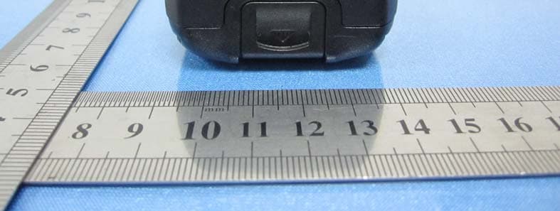
Click to zoom
Application Details
- Equipment Class
- TNF - Licensed Non-Broadcast Transmitter Held to Face
- Date of Grant
- Sep 27, 2010
- Application Purpose
- Original Equipment
- Date of Application
- Sep 27, 2010
- Equipment Note
- Two-way Radio
- Frequency Range
- 450.00000000 - 470.00000000
- Country
- China
Documents & Files
Document Text
Text extracted from the exhibit documents filed with the FCC. Open a document above to read the original.
Users Manual
Preface Thank you for purchasing Hytera TC-508 portable radio. TC-508 is endowed with compact appearance, durable structure, practical functions and reliable performance. It will bring you perfect communication. To derive optimum performance from your radio, please read this manual and the supplied Safety Information Booklet carefully before use TC-508 Owner’s Manual 1 Instructional Icons The following icons are available through this manual: Caution: indicates situations that could cause damage to your radio. Note: indicates tips that can help you make better use of your radio. Term Explanation The following terms will appear through this manual: Key Operation Short press: to press a key and release it quickly. Long press: to press and hold down a key for above 1 second. Hold down: to press a key and remain holding it down. User Mode Refers to the mode entered after you turn on the radio directly. CTCSS/CDCSS The signaling can help you prevent unwanted conversations at the same frequency. TC-508 Owner’s Manual 2 Copyright Information Hytera, CRS and HYT are the trademark or registered trademark of Hytera Communications Corporation Limited (hereinafter referred to as “Hytera”) in PRC and other countries and/or areas. Hytera retains the ownership of its trademarks and product names. All other trademarks and/or product names that may be used in this manual are properties of their respective owners. The Hytera product described in this manual may include Hytera computer programs stored in memory or other media. Laws in the PRC and/or other countries or areas preserve for Hytera exclusive rights for Hytera computer programs. The purchase of this product shall not be deemed to grant, either directly or by implication, any rights to the purchaser regarding Hytera computer programs. Any Hytera computer programs may not be copied, modified, distributed, decompiled, or reverse-engineered in any manner without the prior written consent of Hytera. Disclaimer Hytera endeavors to achieve the accuracy and completeness of this manual, but no warranty of accuracy or reliability is given. All the specifications and designs are subject to change without prior notice due to continuous technology development. No part of this manual may be copied, modified, translated, or distributed in any manner without the express written permission of Hytera. If you have any suggestions or would like to learn more details, please visit our website at: http://www.hytera.cn . TC-508 Owner’s Manual 3 RF Energy Exposure Compliance ● Your radio is designed and tested to comply with a number of national and international standards and guidelines (listed below) regarding human exposure to radio frequency electromagnetic energy. This radio complies with the IEEE and ICNIRP exposure limits for occupational/controlled RF exposure environment at operating duty factors of up to 50% transmitting and is authorized by the FCC for occupational use only. In terms of measuring RF energy for compliance with the FCC exposure guidelines, your radio radiates measurable RF energy only while it is transmitting (during talking in VOX and PTT mode), not when it is receiving (listening) or in standby mode. ● The device complies with SAR and/or RF field strength limits of RSS-102 requirement and contact information where the user can obtain Canadian information on RF exposure and compliance. Your radio complies with the following of RF energy exposure standards and guidelines ● United States Federal Communications Commission, Code of Federal Regulations; 47CFR part 2 sub-part J ● American National Standards Institute (ANSI)/Institute of Electrical and Electronic Engineers (IEEE) C95. 1-1992 ● Institute of Electrical and Electronic Engineers (IEEE) C95. 1-1999 Edition ● International Commission on Non-Ionizing Radiation Protection (ICNIRP) 1998 Operational Instructions and Training Guidelines To ensure optimal performance and compliance with the occupational/controlled environment RF energy exposure limits in the above standards and guidelines, users should transmit no more than 50% of the time and always adhere to the following procedures: Transmit and Receive To transmit (talk), push the Push-To-Talk (PTT) key; to receive, release the PTT key. EU Regulatory Conformance The equipment is in compliance with the essential requirements and other relevant provisions of the Directive 1999/5/EC. Note: The above information is applicable to EU countries only. TC-508 Owner’s Manual 4 FCC Licensing Information Part 15 Compliance This equipment has been tested and found to comply with the limits for a Class B digital device, pursuant to part 15 of the FCC Rules. These limits are designed to provide reasonable protection against harmful interference in a residential installation. This equipment generates, uses and can radiate radio frequency energy and, if not installed and used in accordance with the instructions, may cause harmful interference to radio communications. However, there is no guarantee that interference will not occur in a particular installation. If this equipment does cause harmful interference to radio or television reception, which can be determined by turning the equipment off and on, the user is encouraged to try to correct the interference by one or more of the following measures: Reorient or relocate the receiving antenna. Increase the separation between the equipment and receiver. Connect the equipment into an outlet on a circuit different from that to which the receiver is connected. Consult the dealer or an experienced radio/TV technician for help. FCC Licensing Requirements A license from Federal Communications Commission is required prior to use. Your dealer will program each radio with your authorized frequencies, signaling codes, etc., and will be there to meet your communications needs as your system expands. Contact your dealer for more information. TC-508 Owner’s Manual 5 Contents Checking Items in the Package ..............…
Text truncated - open the document above for the full version.
Cover Letter(s)
Hytera Communications Corporation Ltd. Federal Communications Commission 7435 Oakland Mills Road Columbia, MD 21046 Gentlemen: This letter is to comply with Sections 0.457 and 0.459 pertaining to confidential material. Hytera Communications Corporation Ltd. would like the following documents regarding this submission for FCC ID: YAMTC-508U2 to be kept confidential. 1. Block Diagram 2. Schematic 3. Theory of Operation 4. Tune-Up Procedure The above material contains trade secrets or technical data, which would customarily be guarded from competitors. We do not want these documents to be accessible to the general public. Sincerely yours, Hytera Communications Corporation Ltd. Xiong Lei/ Director of management dept Fax: +86 755 8613 7130 Tel: +86 755 2697 2999 E-mail:[email protected]
Cover Letter(s)
Justification Letter DATE: September 19, 2010 Federal Communications Commission Authorization & Evaluation Division 7435 Oakland Mills Road Colombia, Maryland 21046 FCC ID: YAMTC-508U2 Model: TC-508 U (2) Dear Sir/Madam, We , Hytera Communications Corporation Ltd. acknowledge that this device will not be marketed to USA users with the frequency band which is not allowed by rule part 90.and it is a violation of FCC rules if this device is operated on unauthorised frequencies inside the U.S.A. We , Hytera Communications Corporation Ltd. acknowledge this equipment meets the requirements of FCC Rules, Parts 90.203 (e) and (g) as applicable. Programming of this product's transmit frequencies can be performed ONLY by the manufacturer or by service or maintenance personnel. The operator cannot program transmit frequencies using the equipment's external operation. Sincerely yours, Hytera Communications Corporation Ltd. Xiong Lei/ Director of management dept Fax: +86 755 8613 7130 Tel: +86 755 2697 2999 E-mail:[email protected]
External Photos
External photos of the EUT
ID Label/Location Info
FCC Label FCC RF Warning Label
Internal Photos
Internal photos of the EUT
Parts List/Tune Up Info
TC-508 Service Manual 65 No. Part No Description Qty (PCS). 1 6001139000000 Front case 1 2 6100312000010 Silicone rubber PTT key 1 3 6000842100010 Plastic PTT key 1 4 7101904020200 Self-tapping screw ST1.94.0mm 10 5 PCB main board 1 6 6100542100000 Waterproof ring for radio 1 7 6300115000000 Aluminum chassis 1 8 7102508000010 Machine screw M2.58.0mm 1 9 41005002004B0 PTT Key PCB 1 10 7300032000000 Metal dome for PTT key 1 11 7102504000300 Machine screw M2.54.0mm 2 12 1602L13000000 Li-Ion battery pack 1 13 1605040000000 Belt Clip Kit With Metal Bracket 1 14 7103006004000 Machine screw M3.06.0mm 2 15 6001140000000 Rear cover 1 16 4400100008000 SMA RF connector 1 17 6100335000000 Antenna O-Ring 1 18 6100370000000 O-ring washer for the switch 2 19 4304030000010 Gray code rotary switch 1 20 4302020000140 Volume switch 1 21 6100314000000 Waterproof ring for battery connector 1 22 6000852000000 Bracket for earpiece jack 1 23 16010415W0050 Antenna 1 24 6000845100010 Channel selector knob 1 25 6000846100000 Volume control knob 1 26 6201739000000 Inner lining for knob 1 27 6201066000000 Inner lining for knob 1 28 7207002200200 Nut 2 29 6000854000000 Light guide 1 30 6201870000000 Speaker fixing sheet 1 31 5001210000470 Speaker 1 32 6100077000000 Speaker washer 1 33 7400322000000 Speaker felt 1 34 6000749000000 Accessory jack cover 1 35 5002220000070 Microphone 1 36 6100345000000 Mic cover 1 37 7400141000000 MIC mesh 1 Note: Parts that are not marked with material number may vary with radio frequency band. TC-508 Service Manual 37 No.Part No.DescriptionQty. Ref No. Print No. 443001051020000 Chip resistor 1KΩ F 1/16W 0402 (RoHS)1R697B4J 453001051020000 Chip resistor 1KΩ F 1/16W 0402 (RoHS)1R698B4J 463001051030000 Chip resistor 10KΩ J 1/16W 0402 (RoHS)1R103T5I 473001051030000 Chip resistor 10KΩ J 1/16W 0402 (RoHS)1R107T4H 483001051030000 Chip resistor 10KΩ J 1/16W 0402 (RoHS)1R208B2H 493001051030000 Chip resistor 10KΩ J 1/16W 0402 (RoHS)1R219B1F 503001051030000 Chip resistor 10KΩ J 1/16W 0402 (RoHS)1R314T1I 513001051030000 Chip resistor 10KΩ J 1/16W 0402 (RoHS)1R412T5E 523001051030000 Chip resistor 10KΩ J 1/16W 0402 (RoHS)1R413T3F 533001051030000 Chip resistor 10KΩ J 1/16W 0402 (RoHS)1R428B4E 543001051030000 Chip resistor 10KΩ J 1/16W 0402 (RoHS)1R430T3G 553001051030000 Chip resistor 10KΩ J 1/16W 0402 (RoHS)1R433T3F 563001051030000 Chip resistor 10KΩ J 1/16W 0402 (RoHS)1R616B2I 573001051030000 Chip resistor 10KΩ J 1/16W 0402 (RoHS)1R617B2I 583001051040000 Chip resistor 100KΩ F 1/16W 0402 (RoHS)1R113T5F 593001051040000 Chip resistor 100KΩ F 1/16W 0402 (RoHS)1R120T4I 603001051040000 Chip resistor 100KΩ F 1/16W 0402 (RoHS)1R213B2H 613001051040000 Chip resistor 100KΩ F 1/16W 0402 (RoHS)1R513T3E 623001051040000 Chip resistor 100KΩ F 1/16W 0402 (RoHS)1R517T2F 633001051040000 Chip resistor 100KΩ F 1/16W 0402 (RoHS)1R518T2F 643001051040000 Chip resistor 100KΩ F 1/16W 0402 (RoHS)1R521T2E 653001051040000 Chip resistor 100KΩ F 1/16W 0402 (RoHS)1R522T3E 663001051040000 Chip resistor 100KΩ F 1/16W 0402 (RoHS)1R526T2E 673001051040000 Chip resistor 100KΩ F 1/16W 0402 (RoHS)1R603B5I 683001051050000 Chip resistor 1MΩ F 1/16W 0402 (RoHS)1R218B1F 693001051050000 Chip resistor 1MΩ F 1/16W 0402 (RoHS)1R405B4E 703001051050000 Chip resistor 1MΩ F 1/16W 0402 (RoHS)1R435B3E 713001051050000 Chip resistor 1MΩ F 1/16W 0402 (RoHS)1R501T2H 723001051230000 Chip resistor 12KΩ J 1/16W 0402 (RoHS)1R206B4I 733001051230000 Chip resistor 12KΩ J 1/16W 0402 (RoHS)1R224B5I 743001051230000 Chip resistor 12KΩ J 1/16W 0402 (RoHS)1R512T3E 753001051230000 Chip resistor 12KΩ J 1/16W 0402 (RoHS)1R544T3J 763001051510000 Chip resistor 150Ω J 1/16W 0402 (RoHS)1R115T4G 773001051530000 Chip resistor 15K Ω J 1/16W 0402 (RoHS)1R543T4J 783001051540020 Chip resistor 150KΩ J 1/16W 0402 (RoHS)1R523T1F 793001051540020 Chip resistor 150KΩ J 1/16W 0402 (RoHS)1R545T3J 803001051820000 Chip resistor 1.8KΩ J 1/16W 0402 (RoHS)1R414T4E 813001051220000 Chip resistor 1.2KΩ J 1/16W 0402 (RoHS)1R529T1G 823001051840000 Chip resistor 180KΩ J 1/16W 0402 (RoHS)1R528T2G 833001052200000 Chip resistor 22Ω J 1/16W 0402 (RoHS)1R651B1H 843001052210000 Chip resistor 220Ω J 1/16W 0402 (RoHS)1R126T3G 853001052210000 Chip resistor 220Ω J 1/16W 0402 (RoHS)1R201B1F 863001052210000 Chip resistor 220Ω J 1/16W 0402 (RoHS)1R516T1G 873001052210000 Chip resistor 220Ω J 1/16W 0402 (RoHS)1R519T3E TC-508 Service Manual 38 No.Part No.DescriptionQty. Ref No. Print No. 883001052220010 Chip resistor 2.2KΩ F 1/16W 0402 (RoHS)1R202B1F 893001052220010 Chip resistor 2.2KΩ F 1/16W 0402 (RoHS)1R216B2H 903001052220010 Chip resistor 2.2KΩ F 1/16W 0402 (RoHS)1R507T2H 913001052220010 Chip resistor 2.2KΩ F 1/16W 0402 (RoHS)1R510T3J 923001052230010 Chip resistor 22KΩ J 1/16W 0402 (RoHS)1R215B2H 933001052230010 Chip resistor 22KΩ J 1/16W 0402 (RoHS)1R559T3I 943001052240000 Chip resistor 220KΩ J 1/16W 0402 (RoHS)1R509T3H 953001052240000 Chip resistor 220KΩ J 1/16W 0402 (RoHS)1R562T2I 963001052240000 Chip resistor 220KΩ J 1/16W 0402 (RoHS)1R602B5I 973001052240000 Chip resistor 220KΩ J 1/16W 0402 (RoHS)1R649B1H 983001052710000 Chip resistor 270Ω F 1/16W 0402 (RoHS)1R537T2G 993001053310000 Chip resistor 330Ω F 1/16 0402 (RoHS)1R409T4F 100 3001053310000 Chip resistor 330Ω F 1/16 0402 (RoHS)1R432T3G 101 3001053320000 Chip resistor 3.3KΩ J 1/16W 0402 (RoHS)1R110T4H 102 3001053320000 Chip resistor 3.3KΩ J 1/16W 0402 (RoHS)1R203B2H 103 3001053320000 Chip resistor 3.3KΩ J 1/16W 0402 (RoHS)1R204B2H 104 3001053320000 Chip resistor 3.3KΩ J 1/16W 0402 (RoHS)1R431T3G 105 3001053320000 Chip resistor 3.3KΩ J 1/16W 0402 (RoHS)1R536T3I 106 3001053320000 Chip resistor 3.3KΩ J 1/16W 0402 (RoHS)1R538T3I 107 3001053320000 Chip resistor 3.3KΩ J 1/16W 0402 (RoHS)1R561T3I 108 3001053330010 Chip resistor 33KΩ J 1/16W 0402 (RoHS)1R125T5I 109 3001053330010 Chip resistor 33KΩ J 1/16W 0402 (RoHS)1R416T5E 110 3001053330010 Chip resistor 33KΩ J 1/16W 0402 (RoHS)1R542T4J 111 3001053330010 Chip resistor 33KΩ J 1/16W 0402 (RoHS)1R563T3J 112 30010…
Text truncated - open the document above for the full version.
Test Report
Report No.: RZA2010-1423-R2 TESTING No. L2264 OET 65 TEST REPORT Product Name Two-Way Radio Model TC-508 U(2) FCC ID YAMTC-508U2 Client Hytera Communications Corporation Ltd. TA Technology (Shanghai) Co., Ltd. GENERAL SUMMARY Product Name Two-Way Radio Model TC-508 U(2) FCC ID YAMTC-508U2 Report No. RZA2010-1423-R2 Client Hytera Communications Corporation Ltd. Manufacturer Hytera Communications Corporation Ltd. Reference Standard(s) IEEE Std C95.1, 1999: IEEE Standard for Safety Levels with Respect to Human Exposure to Radio Frequency Electromagnetic Fields, 3 KHz to 300 GHz. IEEE Std 1528™-2003: IEEE Recommended Practice for Determining the Peak Spatial-Average Specific Absorption Rate (SAR) in the Human Head from Wireless Communications Devices: Measurement Techniques. SUPPLEMENT C Edition 01-01 to OET BULLETIN 65 Edition 97-01 June 2001 including DA 02-1438 June 19, 2002: Evaluating Compliance with FCC Guidelines for Human Exposure to Radiofrequency Electromagnetic Fields Additional Information for Evaluation Compliance of Mobile and Portable Devices with FCC Limits for Human Exposure to Radiofrequency Emissions. Conclusion This portable wireless equipment has been measured in all cases requested by the relevant standards. Test results in Chapter 7 of this test report are below limits specified in the relevant standards. General Judgment: Pass (Stamp) Date of issue: September 17 th , 2010 Comment The test result only responds to the measured sample. Approved by Yang Weizhong Revised by Ling Minbao Performed by Xue Chaofeng TA Technology (Shanghai) Co., Ltd. Test Report Report No. RZA2010-1423-R2 Page 3 of 60 TABLE OF CONTENT 1. General Information ..................................................................................................................... 4 1.1. Notes of the Test Report.......................................................................................................4 1.2. Testing Laboratory ................................................................................................................ 4 1.3. Applicant Information ............................................................................................................ 5 1.4. Manufacturer Information ...................................................................................................... 5 1.5. Information of EUT................................................................................................................ 6 1.6. The Maximum SAR Values of Each Tested Band................................................................. 7 1.7. Test Date .............................................................................................................................. 7 2. Operational Conditions during Test ..............................................................................................8 3. SAR Measurements System Configuration .................................................................................. 9 3.1. SAR Measurement Set-up .................................................................................................... 9 3.2. DASY4 E-field Probe System ............................................................................................. 10 3.2.1. ET3DV6 Probe Specification ....................................................................................... 10 3.2.2. E-field Probe Calibration .............................................................................................. 11 3.3. Other Test Equipment ......................................................................................................... 11 3.3.1. Device Holder for Transmitters .................................................................................... 11 3.3.2. Phantom...................................................................................................................... 12 3.4. Scanning Procedure........................................................................................................... 12 3.5. Data Storage and Evaluation .............................................................................................. 14 3.5.1. Data Storage................................................................................................................ 14 3.5.2. Data Evaluation by SEMCAD ...................................................................................... 14 3.6. System Check..................................................................................................................... 17 3.7. Equivalent Tissues ..............................................................................................................18 4. Laboratory Environment............................................................................................................. 18 5. Charcteristics of the Test ............................................................................................................ 19 5.1. Applicable Limit Regulations ............................................................................................... 19 5.2. Applicable Measurement Standards................................................................................... 19 6. Conducted Output Power Measurement.................................................................................... 20 6.1. Conducted Power Results .................................................................................................. 20 7. Test Results ............................................................................................................................... 21 7.1. Dielectric Performance........................................................................................................ 21 7.2. System Check Results ........................................................................................................ 21 7.3. Summary of Measurement Results...........................................…
Text truncated - open the document above for the full version.
Test Report
FCC PART 90 TEST REPORT FCC Part 90 Report Reference No......................: FCC ID..............................................: WE10090014 YAMTC-508U2 Compiled by ( position+printed name+signature)..: File administrators Wenliang Li Supervised by ( position+printed name+signature)..: Test Engineer Eric Zhang Approved by ( position+printed name+signature)..: Manager Jimmy Li Date of issue.....................................: Sep 20, 2010 Testing Laboratory Name..............: Shenzhen Huatongwei International Inspection Co., Ltd Address ............................................: Keji Nan No.12 Road, Hi-tech Park, Shenzhen, China Applicant’s name............................: Hytera Communications Corporation Ltd. Address ............................................: HYT Tower,Hi-Tech Industrial Park North,Nanshan District,Shenzhen China.518057 Test specification: Standard ...........................................: FCC Part 90: PRIVATE LAND MOBILE RADIO SERVICES TRF Originator..................................: Shenzhen Huatongwei International Inspection CO., Ltd Master TRF.......................................: Dated 2006-06 Shenzhen Huatongwei International Inspection Co., Ltd. All rights reserved. This publication may be reproduced in whole or in part for non-commercial purposes as long as the Shenzhen Huatongwei International Inspection Co., Ltd is acknowledged as copyright owner and source of the material. Shenzhen Huatongwei International Inspection Co., Ltd takes no responsibility for and will not assume liability for damages resulting from the reader's interpretation of the reproduced material due to its placement and context. Test item description .....................: Two-way Radio Trade Mark .......................................: Model/Type reference.......................: TC-508 U(2) Listed Models ..................................: / Ratings .............................................: DC 7.40V Modulation .......................................: FM Channel Separation........................... 12.5KHz&25KHz Rated Power ..................................... 4Watts(36.02dBm)/2Watts(33dBm) Operation Frequency Range ............. From 450 MHz to 470 MHz Result................................................: Positive V1.0 Page 2 of 84 Report No.: WE10090014 FCC ID: YAMTC-508U2 T E S T R E P O R T Test Report No. : WE10090014 Sep 20, 2010 ______________________________________________________________________________________________ Date of issue Equipment under Test : Two-way Radio Model /Type : TC-508 U(2) Listed Models : / Applicant : Hytera Communications Corporation Ltd. Address : HYT Tower,Hi-Tech Industrial Park North,Nanshan District,Shenzhen China.518057 Manufacturer : Hytera Communications Corporation Ltd. Address : HYT Tower,Hi-Tech Industrial Park North,Nanshan District,Shenzhen China.518057 Test Result according to the standards on page 4: Positive The test report merely corresponds to the test sample. It is not permitted to copy extracts of these test result without the written permission of the test laboratory. V1.0 Page 3 of 84 Report No.: WE10090014 FCC ID: YAMTC-508U2 Contents 1. TEST STANDARDS 4 2. SUMMARY 5 2.1. General Remarks 5 2.2. Product Description 5 2.3. Equipment under Test 5 2.4. Short description of the Equipment under Test (EUT) 5 2.5. EUT Configuration 6 2.6. EUT operation mode 6 2.7. EUT configuration 6 2.8. Related Submittal(s) / Grant (s) 6 2.9. Modifications 6 2.10. Note 6 3. TEST ENVIRONMENT 7 3.1. Address of the test laboratory 7 3.2. Test Facility 7 3.3. Environmental conditions 8 3.4. Configuration of Tested System 8 3.5. Discription of Tested Modes 8 3.6. Statement of the measurement uncertainty 8 3.7. Test Description 9 3.8. Equipments Used during the Test 9 4. TEST CONDITIONS AND RESULTS 11 4.1. Conducted Emissions Test 11 4.2. Occupied Bandwidth and Emission Mask Test 14 4.3. Transmitter Radiated Spurious Emssion 25 4.4. Spurious Emssion on Antenna Port 30 4.5. Modulation Charcateristics 44 4.6. Frequency Stability Test 49 4.7. Maximum Transmitter Power 51 4.8. Transmitter Frequency Behavior 58 4.9. Receiver Radiated Spurious Emssion 61 4.10. Receiver Conducted Spurious Emssion 67 5. TEST SETUP PHOTOS OF THE EUT 74 6. EXTERNAL AND INTERNAL PHOTOS OF THE EUT 77 V1.0 Page 4 of 84 Report No.: WE10090014 FCC ID: YAMTC-508U2 1. TEST STANDARDS The tests were performed according to following standards: FCC Rules Part 90: PRIVATE LAND MOBILE RADIO SERVICES. TIA/EIA 603: Land Mobile FM or PM Communications Equipment Measurement and Performance Standards. ANSI C63.4-2009 : American National Standard for Methods of Measurement of Radio-Noise Emissions from Low-Voltage Electrical and Electronic Equipment in the Range of 9 kHz to 40 GHz. V1.0 Page 5 of 84 Report No.: WE10090014 FCC ID: YAMTC-508U2 2. SUMMARY 2.1. General Remarks Date of receipt of test sample : Sep 13, 2010 Testing commenced on : Sep 13, 2010 Testing concluded on : Sep 20, 2010 2.2. Product Description The Hytera Communications Corporation Ltd.’s Model: TC-508 U(2) or the “EUT” as referred to in this report; more general information as follows: Name of EUT Two-way Radio Model Number TC-508 U(2) FCC ID YAMTC-508U2 Rated Output Power 4Watts(36.02dBm)/2Watts(33.00dBm) Modilation Type FM for Analog Voice 16K0F3E for 25KHz Channel Separation Emission Designator Analog 11K0F3E for 12.5KHz Channel Separation Channel Separation Analog Voice 12.5KHz&25KHz Antenna Type External Frequency Range From 450 MHz to 470 MHz 4.67 W for 25 KHz Channel Separation Maximum Transmitter Power Analog 4.67 W for 12.5 KHz Channel Separation 2.3. Equipment under Test Power supply system utilised Power supply voltage : ○ 120V / 60 Hz ○ 115V / 60Hz ○ 12 V DC ○ 24 V DC ● Other (specified in blank below) DC 7.40V from battery Test frequency list Modulation Type Test Channel Test Frequency Bottom Channel 450.1250 MHz Middle Channel 460.1250 MHz Analog/FM Top Channel 469.9875 MHz 2.4. Short descriptio…
Text truncated - open the document above for the full version.
Test Setup Photos
Test setup photos of the EUT
Contact Information
Applicant
Ruifen Huang(Certification Engineer)
Test Firm
Shenzhen Huatongwei International Insp. Co., LtdMoffy Yu
Technical Specifications
| # | Rule Parts | Frequency Range | Power Output | Emission | Tolerance |
|---|---|---|---|---|---|
| 4 | 9 | 450 MHz - 470 MHz | 2.27 W | 16K0F3E | 1.42 ppm |
Other Applications from Hytera Communications Corporation Limited
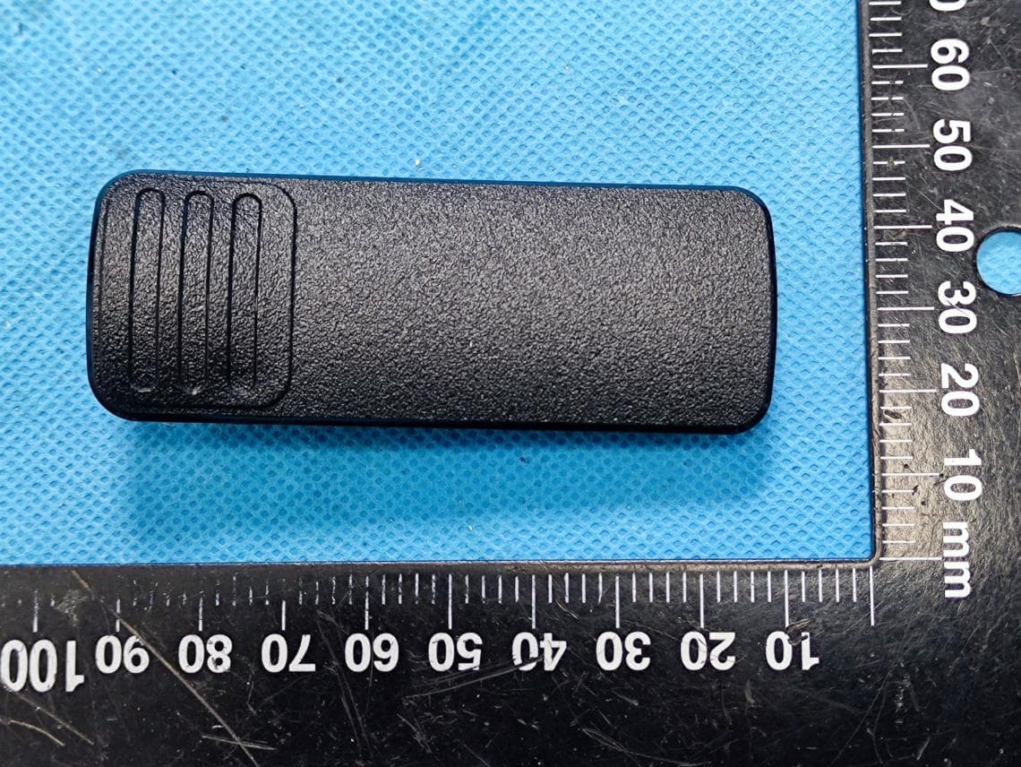
YAMBP516LF
Aug 15, 2022Digital Portable Radio
Equipment Class
FRF - Part 95 Family Radio Face Held Transmitter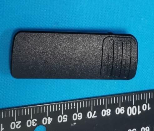
YAMBP5XXVHF
Mar 01, 2022Digital Portable Radio
Equipment Class
DSS - Part 15 Spread Spectrum Transmitter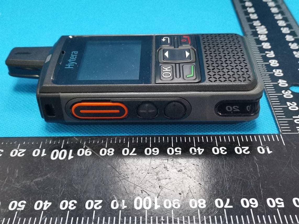
YAMPNC360S
Jan 19, 2022PoC Radio
Equipment Class
DTS - Digital Transmission System
YAMHM78XUVS
Jul 28, 2021DIGITAL MOBILE RADIO
Equipment Class
TNB - Licensed Non-Broadcast Station Transmitter
YAMHP6XXUMS
Jul 22, 2021Digital Portable Radio
Equipment Class
DTS - Digital Transmission System